2004 Mercury Monterey Owner's Manual - Page 199
2004 Mercury Monterey Manual
Page 199 highlights
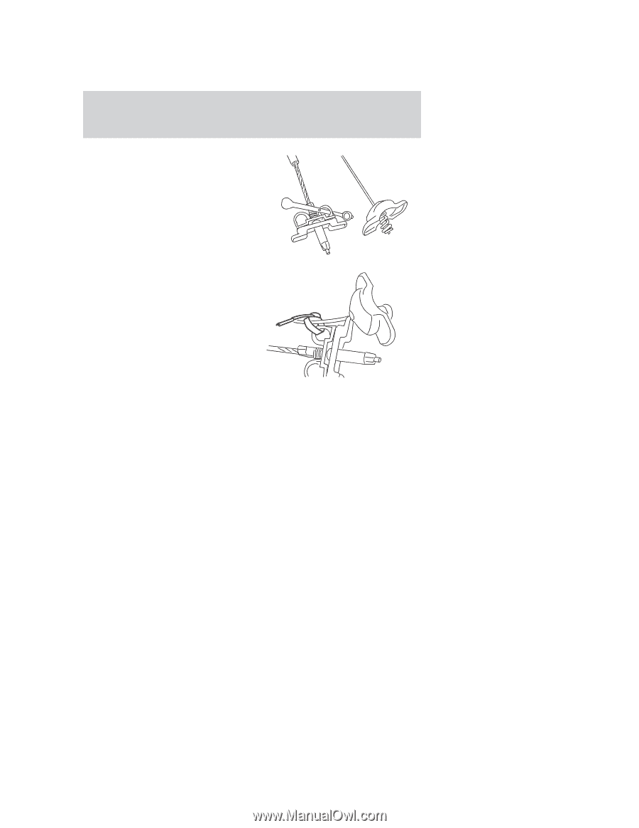
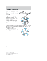
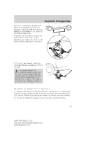
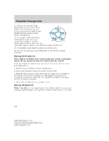
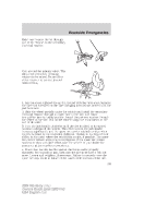
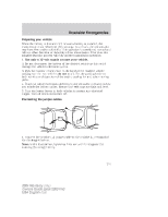
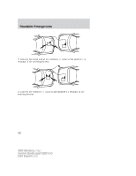
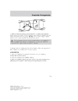
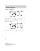
Roadside Emergencies Make sure to pass the tie through one of the "loops" on the secondary (locking) retainer, then around the primary cable. This allows the secondary (locking) retainer to be raised. Do not allow either retainer to contact ground while driving. 1. Lay the spare, inflated tire on the ground with the valve stem facing in the direction specified on the Tire Changing Instructions located with the jack hardware. 2. Slide the wheel partially under the vehicle and install the secondary (locking) retainer through an outer hole in the tire, and rotate one-quarter turn to locked position. Install the primary retainer through the center of the tire. Pull on the cable to align the components at the end of the cable. 3. Turn the jack handle clockwise until the tire is raised to its stowed position underneath the vehicle. The effort to turn the jack handle increases significantly and the spare tire carrier ratchets or slips when the tire is raised to the maximum tightness. Tighten to the best of your ability, to the point where the ratchet/slip occurs, if possible. The spare tire carrier will not allow you to overtighten. If the spare tire carrier ratchets or slips with little effort, take the vehicle to your dealer for assistance at your earliest convenience. 4. Check that the tire lies flat against the frame and is properly tightened. Try to push or pull, then turn the tire to be sure it will not move. Loosen and retighten, if necessary. Failure to properly stow the spare tire may result in failure of the winch cable and loss of the tire. 199 2004 Monterey (mty) Owners Guide (post-2002-fmt) USA English (fus)
-
 1
1 -
2
-
3
-
4
-
5
-
6
-
7
-
8
-
9
-
10
-
11
-
12
-
13
-
14
-
15
-
16
-
17
-
18
-
19
-
20
-
21
-
22
-
23
-
24
-
25
-
26
-
27
-
28
-
29
-
30
-
31
-
32
-
33
-
34
-
35
-
36
-
37
-
38
-
39
-
40
-
41
-
42
-
43
-
44
-
45
-
46
-
47
-
48
-
49
-
50
-
51
-
52
-
53
-
54
-
55
-
56
-
57
-
58
-
59
-
60
-
61
-
62
-
63
-
64
-
65
-
66
-
67
-
68
-
69
-
70
-
71
-
72
-
73
-
74
-
75
-
76
-
77
-
78
-
79
-
80
-
81
-
82
-
83
-
84
-
85
-
86
-
87
-
88
-
89
-
90
-
91
-
92
-
93
-
94
-
95
-
96
-
97
-
98
-
99
-
100
-
101
-
102
-
103
-
104
-
105
-
106
-
107
-
108
-
109
-
110
-
111
-
112
-
113
-
114
-
115
-
116
-
117
-
118
-
119
-
120
-
121
-
122
-
123
-
124
-
125
-
126
-
127
-
128
-
129
-
130
-
131
-
132
-
133
-
134
-
135
-
136
-
137
-
138
-
139
-
140
-
141
-
142
-
143
-
144
-
145
-
146
-
147
-
148
-
149
-
150
-
151
-
152
-
153
-
154
-
155
-
156
-
157
-
158
-
159
-
160
-
161
-
162
-
163
-
164
-
165
-
166
-
167
-
168
-
169
-
170
-
171
-
172
-
173
-
174
-
175
-
176
-
177
-
178
-
179
-
180
-
181
-
182
-
183
-
184
-
185
-
186
-
187
-
188
-
189
-
190
-
191
-
192
-
193
-
 194
194 -
 195
195 -
 196
196 -
 197
197 -
 198
198 -
 199
199 -
 200
200 -
 201
201 -
 202
202 -
 203
203 -
 204
204 -
205
-
206
-
207
-
208
-
209
-
210
-
211
-
212
-
213
-
214
-
215
-
216
-
217
-
218
-
219
-
220
-
221
-
222
-
223
-
224
-
225
-
226
-
227
-
228
-
229
-
230
-
231
-
232
-
233
-
234
-
235
-
236
-
237
-
238
-
239
-
240
-
241
-
242
-
243
-
244
-
245
-
246
-
247
-
248
-
249
-
250
-
251
-
252
-
253
-
254
-
255
-
256
-
257
-
258
-
259
-
260
-
261
-
262
-
263
-
264
-
265
-
266
-
267
-
268
-
269
-
270
-
271
-
272
-
273
-
274
-
275
-
276
-
277
-
278
-
279
-
280
 |
 |