2007 Suzuki Grand Vitara Owner's Manual - Page 171
2007 Suzuki Grand Vitara Manual
Page 171 highlights
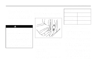
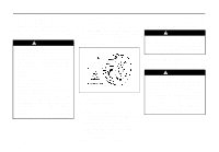
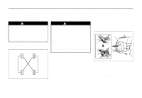
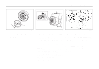
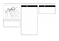
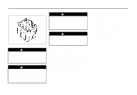
INSPECTION AND MAINTENANCE (B) (1) (2) EXAMPLE 64J179 64J180 81A057 (Half cover type) Remove the center bolt (1), then remove the outer cover (2) of the spare wheel half cover. 2. Pull out the lock cover (B) fitted on the lock nut of the spare wheel while inserting the key full into the key hole of the lock cover (B). 3. Remove the lock nut and wheel nuts of the spare wheel, then remove the spare wheel with both hands. 2) Loosen, but do not remove the wheel nuts. 3) Jack up the vehicle (follow the jacking instructions in the "EMERGENCY SERVICE" section in this manual). 4) Remove the wheel nuts and wheel. 5) Install the new wheel and replace the wheel nuts with their cone shaped end facing the wheel. Tighten each nut snugly by hand until the wheel is securely seated on the hub. Tightening torque for wheel nut 100 Nm (72.3 lb-ft, 10.0 kg-m) 6) Lower the jack and fully tighten the nuts to the specified torque in a crisscross fashion with a wrench as shown in the illustration. NOTE: How to install the spare wheel: When you install the spare wheel to the vehicle again, handle it in the reverse order of removal. 9-30
-
 1
1 -
2
-
3
-
4
-
5
-
6
-
7
-
8
-
9
-
10
-
11
-
12
-
13
-
14
-
15
-
16
-
17
-
18
-
19
-
20
-
21
-
22
-
23
-
24
-
25
-
26
-
27
-
28
-
29
-
30
-
31
-
32
-
33
-
34
-
35
-
36
-
37
-
38
-
39
-
40
-
41
-
42
-
43
-
44
-
45
-
46
-
47
-
48
-
49
-
50
-
51
-
52
-
53
-
54
-
55
-
56
-
57
-
58
-
59
-
60
-
61
-
62
-
63
-
64
-
65
-
66
-
67
-
68
-
69
-
70
-
71
-
72
-
73
-
74
-
75
-
76
-
77
-
78
-
79
-
80
-
81
-
82
-
83
-
84
-
85
-
86
-
87
-
88
-
89
-
90
-
91
-
92
-
93
-
94
-
95
-
96
-
97
-
98
-
99
-
100
-
101
-
102
-
103
-
104
-
105
-
106
-
107
-
108
-
109
-
110
-
111
-
112
-
113
-
114
-
115
-
116
-
117
-
118
-
119
-
120
-
121
-
122
-
123
-
124
-
125
-
126
-
127
-
128
-
129
-
130
-
131
-
132
-
133
-
134
-
135
-
136
-
137
-
138
-
139
-
140
-
141
-
142
-
143
-
144
-
145
-
146
-
147
-
148
-
149
-
150
-
151
-
152
-
153
-
154
-
155
-
156
-
157
-
158
-
159
-
160
-
161
-
162
-
163
-
164
-
165
-
 166
166 -
 167
167 -
 168
168 -
 169
169 -
 170
170 -
 171
171 -
 172
172 -
 173
173 -
 174
174 -
 175
175 -
 176
176 -
177
-
178
-
179
-
180
-
181
-
182
-
183
-
184
-
185
-
186
-
187
-
188
-
189
-
190
-
191
-
192
-
193
-
194
-
195
-
196
-
197
-
198
-
199
-
200
-
201
-
202
-
203
-
204
-
205
-
206
-
207
-
208
-
209
-
210
-
211
-
212
-
213
-
214
-
215
-
216
 |
 |
