3Com 2824 User Manual
3Com 2824 - Baseline Switch Manual
 |
View all 3Com 2824 manuals
Add to My Manuals
Save this manual to your list of manuals |
3Com 2824 manual content summary:
- 3Com 2824 | User Manual - Page 1
Baseline Switch 2816-SFP/2824-SFP Plus User Guide 3C Number: 3C16485A/3C16487 www.3com.com Part No. DUA1648-5AAA03 Published August 2005 - 3Com 2824 | User Manual - Page 2
-14 (June 1987), whichever is applicable. You agree not to remove or deface any portion of any legend provided on any licensed program or documentation contained in, or delivered to you in conjunction with, this User Guide. Unless otherwise indicated, 3Com registered trademarks are registered in the - 3Com 2824 | User Manual - Page 3
the Discovery Application 21 Logging On to the Web Interface 22 Navigating Around the Web Interface 23 Menu 23 Buttons 24 Device Mimic 24 Accessing the Interface Without Using Discovery 25 DHCP Assigned IP Address 25 Manually Assigned (Static) IP Address 25 4 CONFIGURING THE SWITCH Configuration - 3Com 2824 | User Manual - Page 4
Resetting to Factory Defaults 43 Backing Up and Restoring Configuration 44 Upgrade 44 Spanning Tree 45 802.1p Prioritization 46 Viewing Support Information 47 5 TROUBLESHOOTING Forgotten Password 49 Forgotten Static IP Address 49 Solving LED Issues 49 If the Problem Persists 52 A OBTAINING SUPPORT - 3Com 2824 | User Manual - Page 5
notes are available in Adobe Acrobat Reader Portable Document Format (PDF) on the 3Com World Wide Web site: www.3com.com Naming Convention Throughout this guide, the 3Com Baseline Switch 2816/2824-SFP Plus is referred to as the Switch. Category 3 and Category 5 Twisted Pair Cables are referred to as - 3Com 2824 | User Manual - Page 6
(if appropriate) Example: ■ 3Com Baseline Switch 2816-SFP/2824-SFP Plus User Guide ■ Part Number DUA1648-5AAA03 ■ Page 24 Do not use this e-mail address for technical support questions. For information about contacting Technical Support, please refer to "Viewing Support Information" on page 47. The - 3Com 2824 | User Manual - Page 7
the Baseline Switch The 3Com Baseline Switch 2816-SFP/2824-SFP Plus is a versatile, easy-to-use configurable Switch. It is ideal for users who want the high-speed performance of 10/100/1000 switching with the added functionality of Gigabit links, but do not need sophisticated management capabilities - 3Com 2824 | User Manual - Page 8
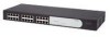
Figure 1 Front and Rear Panels (2816-SFP) 1 1 9 8 4 5 12 13 Baseline Switch 2816-SFP Plus Module Present 8 16 Link/Activity : Green = 1000M, Yellow = 10/1000M, Flash = Activity, Duplex : werden. The Switch has 16 (2816-SFP) or 24 (2824-SFP) 10/100/1000 Mbps auto-negotiating ports. Each - 3Com 2824 | User Manual - Page 9
or to create a high-capacity aggregated link backbone connection. SFP ports are numbered 13 to 16 (2816-SFP) and 21 to 24 (2824-SFP) on the Switch. When an SFP port is active, it has priority over the 10/100/1000 port of the same number. The corresponding 10/100/1000 port is disabled when an - 3Com 2824 | User Manual - Page 10
10 CHAPTER 1: INTRODUCING THE BASELINE SWITCH Table 1 10BASE-T/100BASE-TX Ports Flashing Port disabled or link loopback error. Yellow to Green Off The link has not been established, either nothing is connected to the port, or there is a problem: ■ Check that the attached device is powered on. - 3Com 2824 | User Manual - Page 11
unit. (9) Recovery button The recovery button reinitializes the Switch. This returns the Switch to the factory default settings if, for example, you have forgotten the default IP address, or forgotten your user name or password. CAUTION: 3Com recommends that you back up your configuration settings - 3Com 2824 | User Manual - Page 12
12 CHAPTER 1: INTRODUCING THE BASELINE SWITCH - 3Com 2824 | User Manual - Page 13
Device ■ Using SFP Transceivers ■ Performing Spot Checks Before You Begin WARNING: Safety Information. Before installing or removing any components from the Switch or carrying out any maintenance procedures, read the safety information provided in Appendix C of this guide. AVERTISSEMENT: Consignes - 3Com 2824 | User Manual - Page 14
restricted (3Com recommends that you provide a minimum of 25 mm (1 in.) clearance). ■ The air is possible. Static discharge can cause reliability problems in your equipment. Rack-Mounting or CAUTION: If installing the Switch in a free-standing stack of different size Baseline or Superstack® 3 units - 3Com 2824 | User Manual - Page 15
3 Insert the two screws supplied in the mounting kit, and the fully tighten with a suitable screwdriver. Figure 2 Inserting the Screws Baseline Switch 2816-SFP Plus 4 Repeat the two previous steps for the other side of the unit. 5 Insert the unit into the 19-inch rack and secure with suitable screws - 3Com 2824 | User Manual - Page 16
recesses of the lower unit. Supplying Power to the Switch Power problems can be the cause of serious failures and downtime in end of the power cord into a power outlet. When the Switch is powered on, the Power LED lights up. If the Power LED does not light up, refer to "(6) Power LED" on page 10 - 3Com 2824 | User Manual - Page 17
the Switch Baseline 10/100 Switch Endstations on switched 100 Mbps connections Baseline 10/100 Switch Endstations on switched 100 Mbps connections BaselineBSawsietclihne28S1w6i/t2ch82242-5S0FP Plus 1000 Mbps copper or F iber connection to backbone or server/worksation 1000 Mbps link 10 Mbps - 3Com 2824 | User Manual - Page 18
the latest list of approved SFP transceivers for the Switch on the 3Com Corporation World Wide Web site, enter this URL into your Internet browser: www.3com.com 3Com recommends using 3Com SFPs on the Switch. If you insert an SFP transceiver that is not supported, the Switch will not recognize it - 3Com 2824 | User Manual - Page 19
the other end of the SFP transceiver should slide out easily. Performing Spot Checks At frequent intervals, you should visually check the Switch. Regular checks can give you an early warning of a possible failure; any problems can then be attended to when there will be least effect on users. 3Com - 3Com 2824 | User Manual - Page 20
that no cables are pulled taut Cooling Fan Where possible, check that the cooling fan is operating by listening to the unit. The fan is fitted on the right side of the unit (when viewed from the front). If you experience any problems operating the Switch, refer to "Troubleshooting" on page 49. - 3Com 2824 | User Manual - Page 21
: ■ The Discovery application, which is included on 3Com Baseline Switch 2816-SFP/2824-SFP Plus CD-ROM that is supplied with your Switch ■ A computer that is connected to the Switch and that has a Web browser Running the Discovery Application The 3Com Baseline Switch 2816-SFP/2824-SFP Plus CD-ROM - 3Com 2824 | User Manual - Page 22
Devices screen, click Baseline Switch 2816-SFP/2824-SFP Plus, and then click Next. The Completing the 3Com Discovery Application screen appears. 4 Click Finish. The Web interface loads in your Web browser. Logging On to the Web Interface After the Web interface loads in your Web browser, the first - 3Com 2824 | User Manual - Page 23
The logon page also displays the IP address that the Switch is currently using. Figure 7 Logon Page Navigating Around the Web Interface 23 Menu The menu is located on the left side of the Web interface. When you click an item on the menu, the related information appears in the main section of the - 3Com 2824 | User Manual - Page 24
the administrator password IP Settings Allows you to configure the IP address settings of the Switch Port Configuration Allows you to configure the Switch's port settings VLANs Allows you to create VLAN groups, add port members, and specify how VLAN tagging is used Link Aggregation Allows you - 3Com 2824 | User Manual - Page 25
Without Using Discovery The Discovery application works by automatically detecting the IP address that is assigned to the Switch, and then using that address to connect to the Web interface. If you know the Switch's IP address, you can access the Web interface without using Discovery. This section - 3Com 2824 | User Manual - Page 26
26 CHAPTER 3: CONNECTING TO THE WEB INTERFACE - 3Com 2824 | User Manual - Page 27
's features. Topics include: ■ Configuration Overview ■ Viewing Switch Information ■ Changing the Admin Password ■ Modifying the IP Address Settings ■ Configuring Port Settings ■ Configuring VLANs ■ Configuring Link Aggregation ■ Viewing Statistics ■ Mirroring Port Traffic ■ Running Cable Diagnostic - 3Com 2824 | User Manual - Page 28
■ Management Software Information - Shows the versions of the loader (firmware), boot ROM, and code. If you request for technical assistance from 3Com Support, you may be asked to print out the information on this page. Changing the Admin Password To prevent unauthorized users from accessing the Web - 3Com 2824 | User Manual - Page 29
the Switch, you need to assign an IP address to it - either by DHCP or by manually assigning a static IP address. By default, the Switch performs automatic IP configuration and assigns an IP address to itself. This is necessary for the Discovery application to be able to connect to the Web interface - 3Com 2824 | User Manual - Page 30
default IP address is already in use on the network, then the Switch detects this, and increments the last byte of the MAC address by one to generate its IP address. The IP address would therefore become 169.254.1.3. 3 The Switch repeats step 2 until an unused IP address is found. 3Com recommends - 3Com 2824 | User Manual - Page 31
Management VLAN Indicates the VLAN from which the Web interface can be accessed. By default, all ports belong to VLAN 1. If you create other VLANs, you will only be able to access that Web interface from a computer that belongs to VLAN 1. IP Address Mode Specify how the Switch will get its IP - 3Com 2824 | User Manual - Page 32
, 10 full-duplex, 100-half duplex, and 100 full-duplex. For 1000 Mbps connections, see See "Speed/Duplex for 1000 Mbps Connections" on page 32. Auto (or autonegotiation), which is enabled by default, sets the optimum combination of speed and duplex that can be supported by both ends of the link - 3Com 2824 | User Manual - Page 33
link. Supported SFP transceivers only operate at 1000Mbps full-duplex. Inserting an SFP transceiver into a gigabit port disables the corresponding RJ-45 port, even if no fiber cable is inserted. Advanced Port Configuration Use the Advanced Port Configuration tab to set the Switch's broadcast - 3Com 2824 | User Manual - Page 34
the switch is automatically forwarded to the uplink port or ports. By default, all ports belong to VLAN 1. CAUTION: At least one port must always be a member of VLAN 1 (the management VLAN). If you choose to connect all ports to VLANs other than VLAN 1, you will no longer be able to access the Web - 3Com 2824 | User Manual - Page 35
happens, you will need to reset the Switch to factory settings. To create a VLAN: 1 On the menu, click VLANs. The VLANs page appears. 2 In VLAN ID, click Create New VLAN. 3 In VLAN ID (1-4094), type an unused ID number for the VLAN that you are creating. VLAN IDs range from 1 to 4094. Figure 15 - 3Com 2824 | User Manual - Page 36
THE SWITCH Figure 16 Desktop VLAN Configuration Endstations in VLAN 1 Endstations in VLAN 2 Baseline Switch 2824-SFP Plus add another port to the VLAN or change the port configuration. Setting Up VLAN Across Two Switches This example explains how you can set up a VLAN across two Switches using - 3Com 2824 | User Manual - Page 37
) Server in VLAN 2 (Desktop) Endstation in VLAN 1 (Desktop) To set up the configuration shown in Figure 17, do the following: 1 Create VLAN2 on both Switch 1 and Switch 2, and assign the same name to it. You need not create VLAN1 since it exists by default. Configuring Link Aggregation 37 2 On - 3Com 2824 | User Manual - Page 38
ports to the same remote device in order to achieve higher network throughput. For link aggregation to work, the trunks must be configured on both ends (switches). The Switch does not support the Link Aggregation Control Protocol (LACP), which is specified in IEEE 802.3ad. Guidelines for Creating - 3Com 2824 | User Manual - Page 39
force the settings for speed, duplex mode, and flow control. 2 Click Apply. To delete a trunk, click the corresponding Delete check box, and then click Apply. Configuring Link Aggregation 39 Figure 19 Modify/Delete Tab Viewing the Trunk Summary If you want to view a summary of the trunk settings - 3Com 2824 | User Manual - Page 40
CONFIGURING THE SWITCH Figure 20 Summary Tab Figure 21 Statistics Page Viewing Statistics The Statistics page shows a summary of traffic statistics for all ports, as shown in Figure 21. Figures that appear onscreen indicate the number of packets transmitted (Tx) and received (Rx). ■ To reset all - 3Com 2824 | User Manual - Page 41
latest statistics for the port, click Refresh. Mirroring Port Traffic The Switch allows you to monitor traffic going in and out of a particular for a port: 1 Attach a network analyzer to a port. 2 Access the Web interface, and then click Port Mirroring on the menu. 3 Specify the monitor port and - 3Com 2824 | User Manual - Page 42
Running Cable Diagnostic The Switch provides cable diagnostic, which helps you detect and resolve issues with the attached cables. The Switch can run four types Spanning Tree and 802.1p Prioritization. Restart Pressing the Restart the Switch button has the same effect as power cycling the unit. No - 3Com 2824 | User Manual - Page 43
firmware becomes corrupted, you can reset the Switch to its factory defaults. CAUTION: Resetting the Switch to its factory defaults erases all your settings. You will need to reconfigure the Switch after you reset it. To reset the Switch to factory defaults, click Reset. The Switch LAN IP address - 3Com 2824 | User Manual - Page 44
configuration does not change the password. Upgrade The Upgrade facility allows you to install on the Switch any new releases of system software that 3Com may make available. The newer version of software can be downloaded via HTTP and once copied to the Switch; the Switch will restart and apply the - 3Com 2824 | User Manual - Page 45
software may be corrupted and the Switch may not start up properly afterwards. If the Power LED continues to flash after a failed upgrade, refer to "Troubleshooting" on page 49. Spanning Tree This administrative tool supports the configuration of the Switch bridge assumes that the link to the Root - 3Com 2824 | User Manual - Page 46
Switch is configured to comply with 802.1p, VLAN tagged frames. Traffic prioritization ensures that high priority data is forwarded through the Switch . This ensures that time-sensitive traffic gets the highest level of service. The 802.1D standard specifies eight distinct levels of priority (0 - 3Com 2824 | User Manual - Page 47
Switch allows you to choose between using IP Precedence or DSCP (Differentiated Services Code Point) priority. When either of these services is enabled, the priorities are mapped to a Class of Service value by the Switch, and the traffic then sent to the corresponding output queue. Viewing Support - 3Com 2824 | User Manual - Page 48
48 CHAPTER 4: CONFIGURING THE SWITCH Figure 30 Support Page - 3Com 2824 | User Manual - Page 49
will need to reset the Switch to regain access. See "Resetting to Factory Defaults" on page 43 for instructions. After resetting the Switch, log on to the Web interface using the default admin account settings: ■ User name - admin ■ Password - blank (no password) Forgotten Static IP Address If you - 3Com 2824 | User Manual - Page 50
SFP module is correctly inserted. ■ A 3Com SFP module is being used. Refer to "Approved SFP Transceivers" on page 18 for details. ■ The equipment at the far end is installed and correctly configured. The Link/Activity LED is lit but the network performance of the Switch is poor The Switch supports - 3Com 2824 | User Manual - Page 51
. Solving LED Issues 51 You forget the Switch's default IP address, or you forget the User Name or Password that you assigned to the Switch. The Discovery application can be used for detecting the Switch on the network. Otherwise, you can restore the default settings, using the recovery button on - 3Com 2824 | User Manual - Page 52
52 CHAPTER 5: TROUBLESHOOTING 4 Click on the RESTART THE SWITCH button. 5 Restore the configuration file that you backed up in step 1. Refer to "Configuration" on page 43 for details. If the Problem Persists If the problem persists and the unit still does not operate successfully, contact your - 3Com 2824 | User Manual - Page 53
or extend warranty benefits, contact 3Com or your authorized 3Com reseller. Value-added services like 3Com ExpressSM and GuardianSM can include 24x7 telephone technical support, software upgrades, onsite assistance or advance hardware replacement. Experienced engineers are available to manage your - 3Com 2824 | User Manual - Page 54
product on the 3Com Web site at http://eSupport.3com.com/. First time users will need to apply for a user name and password. A link to software downloads can be found at http://eSupport.3com.com/, or under the Product Support heading at www.3com.com/ Software Upgrades are the software releases that - 3Com 2824 | User Manual - Page 55
611 2000 You can also obtain support in this region using the following e-mail: [email protected] Or request a repair authorization Support and Repair From anywhere in these regions, call: +44 (0)1442 435529 From the following countries, you may use the numbers shown: Contact Us - 3Com 2824 | User Manual - Page 56
speakers, enter the URL: http://lat.3com.com/lat/support/form.html Portuguese speakers, enter the URL: http://lat.3com.com/br/support/form.html English speakers in Latin America should send e-mail to: [email protected] US and Canada Telephone Technical Support and Repair 1 800 876 3266 - 3Com 2824 | User Manual - Page 57
3Com Baseline Switch 2816/2824-SFP Plus has been designed to the following standards: Functional MAC Address EN 55024 Environmental Operating Temperature 0-40 °C (32-113 °F) Humidity 10-95% (non-condensing) Standard EN 60068 (IEC 68)-various parts 100-240 VAC 1 Amp (maximum) 60 W 184.3 BTU/hr - 3Com 2824 | User Manual - Page 58
58 APPENDIX B: TECHNICAL INFORMATION - 3Com 2824 | User Manual - Page 59
following safety information carefully before installing the Baseline Switch 2816-SFP/2824-SFP Plus. WARNING: Installation and removal of the unit must be carried out by qualified personnel only. ■ If installing the Switch unit in a stack with other units, the Switch unit must be installed below the - 3Com 2824 | User Manual - Page 60
UL-approved and CSA certified. ■ The minimum specifications for the flexible cord are: No. 18 AWG cord set must have a rated current capacity of at least 10 A. ■ The attachment plug must be an earth-grounding type avant d'installer le Baseline Switch 2816-SFP/2824-SFP Plus. AVERTISSEMENT: L' - 3Com 2824 | User Manual - Page 61
courant nominal d'au moins 10 A. ■ La prise Baseline Switch 2816-SFP/2824-SFP Plus die folgenden Sicherheitsanweisungen durchlesen. WARNUNG: Die Installation und der Ausbau des Geräts darf nur durch Fachpersonal erfolgen. ■ Wenn der Baseline Switch 2816-SFP Plus mit anderen 3Com Hubs oder Switche - 3Com 2824 | User Manual - Page 62
62 APPENDIX C: SAFETY INFORMATION angeschlossenen Geräte unter SELV-Bedingungen betrieben werden. Stromkabel. Dies muss von dem Land, in dem es benutzt wird geprüft werden: Schweiz ■ Dieser Stromstecker muß die SEV/ASE 1011Bestimmungen einhalten. Europe ■ Das Netzkabel muß vom Typ HO3VVF3GO.75 - 3Com 2824 | User Manual - Page 63
specification for 10 Mbps Ethernet over Category 3, 4 or 5 twisted pair cable. 100BASE-TX The IEEE specification for 100 Mbps Fast Ethernet over Category 5 twisted-pair cable. 1000BASE-LX IEEE 802.3z specification the 1000BASE-T ports to operate at 1000 Mbps, full duplex. Bandwidth The information - 3Com 2824 | User Manual - Page 64
1000 IP addresses to workstations on a network. These assignments are made by the DHCP server software that runs on Windows NT Server. Ethernet A LAN specification developed jointly by Xerox, Intel and Digital Equipment Corporation. Ethernet networks use CSMA/CD to transmit packets at a rate of 10 - 3Com 2824 | User Manual - Page 65
.3ad A standard that defines link aggregation. 802.3ad is now incorporated into the relevant sections of the IEEE Std. 802.3-2002. IETF Internet Engineering Task Force. An organization responsible for providing engineering solutions for TCP/IP networks. In the network management area, this group is - 3Com 2824 | User Manual - Page 66
speeds over short distances (up to 1000 metres). Layer 2 Data Link layer in the ISO 7-Layer Data Communications Protocol. This is related directly to the hardware interface for the network devices and passes on traffic based on MAC addresses. Link Aggregation See Trunking. MAC Media Access Control - 3Com 2824 | User Manual - Page 67
services such as computer files and printer queues. 67 SFP Small From Factor Pluggable (SFP) Connectors are based on an open standard that enables hot swapping of various type of fiber optic and copper-based transceivers into the host equipment. Subnet Address An extension of the IP addressing - 3Com 2824 | User Manual - Page 68
piece when it reaches its destination. IP relates to the address of the end station to which data is being sent, as well as the address of the destination network. Traffic Monitoring Enables the monitoring of port traffic by attaching a network analyzer to one switch port, in order to monitor the - 3Com 2824 | User Manual - Page 69
and, if not installed and used in accordance with the instructions, may cause harmful interference to radio communications. Operation of this user may find the following booklet prepared by the Federal Communications Commission helpful: How to Identify and Resolve Radio-TV Interference Problems - 3Com 2824 | User Manual - Page 70
70 CHAPTER : REGULATORY NOTICES - 3Com 2824 | User Manual - Page 71
64 diagram front panel 8 Discovery 21 DSCP 47 dynamic host control protocol 64 E Ethernet 64 F Fast Ethernet 65 FCC statement 69 Feedback about this User Guide 6 firmware upgrading 44 forgotten default IP address 51 password 51 user name 51 forgotten IP address 49 forgotten password 49 front panel - 3Com 2824 | User Manual - Page 72
subnet mask 67 support 47 Switch positioning 13 restarting 42 switch defined 67 system tools 42 T TCP/IP 66 defined 68 technical specifications 57 traffic 68 traffic prioritization 46 troubleshooting LED-related issues 49 POST failed 17 U upgrading firmware 44 user name default 28 V VCCI statement
-
 1
1 -
 2
2 -
 3
3 -
 4
4 -
 5
5 -
 6
6 -
 7
7 -
8
-
9
-
10
-
11
-
12
-
13
-
14
-
15
-
16
-
17
-
18
-
19
-
20
-
21
-
22
-
23
-
24
-
25
-
26
-
27
-
28
-
29
-
30
-
31
-
32
-
33
-
34
-
35
-
36
-
37
-
38
-
39
-
40
-
41
-
42
-
43
-
44
-
45
-
46
-
47
-
48
-
49
-
50
-
51
-
52
-
53
-
54
-
55
-
56
-
57
-
58
-
59
-
60
-
61
-
62
-
63
-
64
-
65
-
66
-
67
-
68
-
69
-
70
-
71
-
72
 |
 |

www.3com.com
Part No. DUA1648-5AAA03
Published August 2005
Baseline Switch
2816-SFP/2824-SFP Plus
User Guide
3C Number: 3C16485A/3C16487