3Com 2924-PWR User Guide
3Com 2924-PWR - Baseline Switch Plus 24PORT Web Mng 10/100/1000 Manual
 |
UPC - 610839964734
View all 3Com 2924-PWR manuals
Add to My Manuals
Save this manual to your list of manuals |
3Com 2924-PWR manual content summary:
- 3Com 2924-PWR | User Guide - Page 1
3Com® Baseline Switch 2924-PWR Plus User Guide 3CBLSG24PWR www.3Com.com Part Number 10016095 Rev. AA Published June 2007 - 3Com 2924-PWR | User Guide - Page 2
or deface any portion of any legend provided on any licensed program or documentation contained in, or delivered to you in conjunction with, this User Guide. Unless otherwise indicated, 3Com registered trademarks are registered in the United States and may or may not be registered in other countries - 3Com 2924-PWR | User Guide - Page 3
ABOUT THIS GUIDE User Guide Overview This guide provides information about the Web user interface for the 3Com® Baseline Switch 2924-PWR Plus. The Web interface is a network management system that allows you to configure, monitor, and troubleshoot your switch from a remote web browser. The Web - 3Com 2924-PWR | User Guide - Page 4
4 ABOUT THIS GUIDE ■ Configuring VLANs - Provides information for configuring VLANs. VLANs are logical subgroups with a Local Area Network (LAN) which combine user stations and network devices into a single virtual LAN segment, regardless of the physical LAN segment to which they are attached. ■ - 3Com 2924-PWR | User Guide - Page 5
there differs from the information in this guide, follow the instructions in the release notes. Most user guides and release notes are available in Adobe Acrobat guide, other documentation available for the 3Com® Baseline Switch 2924-PWR Plus include the following: ■ Safety and Support Information - 3Com 2924-PWR | User Guide - Page 6
CONTENTS ABOUT THIS GUIDE User Guide Overview 3 Intended Audience 5 Conventions 5 Related Documentation 5 1 GETTING STARTED About the Switch 2924-PWR 14 Summary of Hardware Features 14 Front Panel Detail 15 LED Status Indicators 16 System Specifications 17 Installing the Switch 18 Setting - 3Com 2924-PWR | User Guide - Page 7
Web Interface 31 Multi-Session Web Connections 31 Accessing the 3Com Web Interface 32 Understanding the 3Com Web Interface 33 Device Representation 35 Using the 3Com Web Interface Management Buttons 35 Using Screen and Table Options 36 Saving the Configuration 40 Resetting the Device 41 - 3Com 2924-PWR | User Guide - Page 8
Link Aggregation 107 Modifying Link Aggregation 110 Removing Link Aggregation 112 Viewing LACP 113 Modifying LACP 114 8 CONFIGURING VLANS Viewing VLAN Details 117 Viewing VLAN Port Details 118 Creating VLANs 119 Modifying VLAN Settings 121 Modifying Port VLAN Settings 123 Removing - 3Com 2924-PWR | User Guide - Page 9
CONFIGURING SNMP Defining SNMP Communities 156 Removing SNMP Communities 158 Defining SNMP Traps 159 Removing SNMP Traps 160 13 CONFIGURING QUALITY OF SERVICE Viewing CoS Settings 163 Defining CoS 164 Viewing CoS to Queue 165 Defining CoS to Queue 165 Viewing DSCP to Queue 167 Configuring - 3Com 2924-PWR | User Guide - Page 10
Viewing Voice VLAN Port Definitions 179 Viewing the OUI Summaries 180 Modifying OUI Definitions 182 14 MANAGING SYSTEM FILES Backing Up System Files 186 Restoring Files 187 Restore the Software Image 188 Activating Image Files 189 15 MANAGING POWER OVER ETHERNET DEVICES Viewing PoE Settings - 3Com 2924-PWR | User Guide - Page 11
215 Physical 215 Electrical 216 Switch Features 216 C PIN-OUTS Null Modem Cable 221 PC-AT Serial Cable 221 Modem Cable 222 Ethernet Port RJ-45 Pin Assignments 222 D TROUBLESHOOTING Problem Management 224 Troubleshooting Solutions 224 E 3COM CLI REFERENCE GUIDE Getting Started with the - 3Com 2924-PWR | User Guide - Page 12
F GLOSSARY ...238 G OBTAINING SUPPORT FOR YOUR 3COM PRODUCTS Register Your Product to Gain Service Benefits 244 Solve Problems Online 244 Purchase Extended Warranty and Professional Services 244 Access Software Downloads 245 Contact Us 245 Telephone Technical Support and Repair 245 REGULATORY - 3Com 2924-PWR | User Guide - Page 13
contains introductory information about the 3Com® Baseline Switch 2924-PWR Plus (hereafter called the Switch) and how they can be used in your network. It covers summaries of hardware and software features and also the following topics: ■ About the Switch 2924-PWR ■ Front Panel Detail ■ LED Status - 3Com 2924-PWR | User Guide - Page 14
Power over Ethernet (PoE) and advanced voice-optimized features such as auto-QoS and auto-voice VLAN. This makes the switch ideal for medium businesses and small enterprises seeking to build a secure converged network. The Switch 2924-PWR includes the following model: ■ Baseline Switch 2924-PWR Plus - 3Com 2924-PWR | User Guide - Page 15
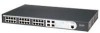
Ethernet Ports SFP Ethernet Ports Supports fiber Gigabit Ethernet long-wave (LX), and fiber Gigabit Ethernet short-wave (SX) transceivers in any combination. Mounting 19-inch rack or standalone mounting Front Panel Detail Figure 1 shows the front panel of the Switch 2924-PWR Plus 24-Port - 3Com 2924-PWR | User Guide - Page 16
of the LEDs. Table 2 Description on the LEDs of the Switch 2924-PWR LED Power Label Power 10/100/1000 BASE-T Ethernet port status Link/ Activity Duplex mode Duplex 1000Base SFP SFP port status Module Active PoE status PoE Status Status Green Yellow OFF Green Yellow OFF Yellow OFF Green - 3Com 2924-PWR | User Guide - Page 17
AC Input voltage Power consumption (full load) Operating temperature Relative humidity Switch 2924-PWR Plus 24-Port 3CBLSG24PWR 44×440× 265 mm (1.73 17.3 10.43 in.) 3.6 kg (7.9 lb) One Console port 24 × 10/100/1000 Mbps Ethernet ports Four Gigabit SFP - 3Com 2924-PWR | User Guide - Page 18
that you need to install and set up your 3Com switch. WARNING: Safety Information. Before you install or remove any components from the Switch or carry out any maintenance procedures, you must read the 3Com Switch Family Safety and Regulatory Information document enclosed. AVERTISSEMENT: Consignes - 3Com 2924-PWR | User Guide - Page 19
Interface through the Console port for basic operations of the switch including setting and viewing the IP address, configuring user accounts, upgrading switch firmware, and more. Refer to "3Com CLI Reference Guide" on page 227. Web Interface Each switch has an internal set of web pages that allow - 3Com 2924-PWR | User Guide - Page 20
3Com Network Director software, available from the 3Com website. Figure 3 SNMP Management over the Network SNMP Network Management Workstation Switch Connect over Network using SNMP Switch to: ■ Configure IP information manually for your switch or view the automatically configured IP information - 3Com 2924-PWR | User Guide - Page 21
Power Up the Switch. Plug and Play Setup Is a DHCP server present? Yes No IP Information is automatically configured using DHCP See page 22 The switch uses its default IP information See page 22 Initial IP Information Setup Do you want to manually the switch your Switch? switch from unauthorized - 3Com 2924-PWR | User Guide - Page 22
's IP configuration is determined automatically using DHCP, or manually using values you assign. Automatic IP Configuration using DHCP By default the switch tries to configure its IP Information without requesting user intervention. It tries to obtain an IP address from a DHCP server on the network - 3Com 2924-PWR | User Guide - Page 23
port to manually set the IP address, or to view the IP address that was assigned automatically (for example, by a DHCP server). For more information about the CLI, refer to "3Com CLI Reference Guide" on page 227. Connecting to the This section describes how to connect to your switch through the - 3Com 2924-PWR | User Guide - Page 24
to the documentation that accompanies the terminal emulation software for more information. 3 Power up the switch. The Power on Self Test (POST) will be performed. The Switch 2924-PWR takes approximately one minute to boot. Manually set the IP Address using the Console Port You are now ready to - 3Com 2924-PWR | User Guide - Page 25
completes within one minute after the switch is connected to the network and powered up. 1 Connect to the switch Console port as described in " sequence begins as soon as the switch detects a connection to its console port. 3 At the login prompt, enter admin as your user name and press Return. 4 - 3Com 2924-PWR | User Guide - Page 26
Select menu option# The initial set up of your switch is now complete and the switch is ready for you to set up your chosen management method. See "Methods of Managing a Switch" on page 19. For more information about the CLI, refer to "3Com CLI Reference Guide" on page 227. If you do not intend - 3Com 2924-PWR | User Guide - Page 27
your browser. These features are enabled on a browser by default. You will only need to enable them if you have changed your browser settings. The switch's Web interface supports both secure (HTTPS) and non-secure (HTTP) connections. - 3Com 2924-PWR | User Guide - Page 28
networks of all sizes and complexity. See "3Com Network Management" on page 212. Be sure the management workstation is connected to the switch using a port in VLAN 1 (the Default VLAN). By default, all ports on the switch are in VLAN 1. To display and configure SNMP management parameters, refer - 3Com 2924-PWR | User Guide - Page 29
Passwords If you intend to manage the switch or to change the default passwords, you must log in with a valid user name and password. The switch has one default user name. The default user is listed in Table 5. Table 5 Default Users Default User Name Password admin (no password) Access Level - 3Com 2924-PWR | User Guide - Page 30
2 USING THE 3COM WEB INTERFACE This section provides an introduction to the user interface, and includes the following topics: ■ Starting the 3Com Web Interface ■ Understanding the 3Com Web Interface ■ Saving the Configuration ■ Resetting the Device ■ Restoring Factory Defaults ■ Logging Off the - 3Com 2924-PWR | User Guide - Page 31
local database. A unique password is required of each user. Two access levels exist on the 3Com Web Interface: ■ Management access level - Provides the user with read/write access. There is always one management level user configured for the switch. The factory default is be username: admin with no - 3Com 2924-PWR | User Guide - Page 32
32 CHAPTER 2: USING THE 3COM WEB INTERFACE Accessing the 3Com This section contains information on starting the 3Com Web interface. Web Interface To access the 3Com user interface: 1 Open an Internet browser. 2 Enter the device IP address in the address bar and press Enter. The Enter Network - 3Com 2924-PWR | User Guide - Page 33
Web Interface Home Page Understanding the 3Com Web Interface The 3Com Web Interface Home Page contains the following views: ■ Tab View - Provides the device summary configuration located at the top of the home page. ■ Tree View - - 3Com 2924-PWR | User Guide - Page 34
following additional information: ■ Device Representation - Provides an explanation of the user interface buttons, including both management buttons and task icons. ■ Using the 3Com Web Interface Management Buttons - Provides instructions for adding, modifying, and deleting configuration parameters. - 3Com 2924-PWR | User Guide - Page 35
The 3Com Web please refer to Configuring Ports. Using the 3Com Web Interface Management Buttons Configuration Management buttons include the following: Table 7: 3Com Web Interface Configuration Buttons Button configuration settings. Table 8: Ta b 3Com Web Interface Information Tabs Tab Name - 3Com 2924-PWR | User Guide - Page 36
WEB INTERFACE Using Screen and Table Options The 3Com Web interface contains screens and tables for configuring devices. This section contains the following topics: ■ Viewing Configuration Information ■ Adding Configuration Information ■ Modifying Configuration Information ■ Removing - 3Com 2924-PWR | User Guide - Page 37
Using Screen and Table Options 37 Adding Configuration Information User-defined information can be added to specific 3Com Web Interface pages, by opening the IP Setup Page. To configure IP Setup: 1 Click Administration > IP Setup. The IP Setup Page opens: Figure 11 IP - 3Com 2924-PWR | User Guide - Page 38
38 CHAPTER 2: USING THE 3COM WEB INTERFACE Modifying Configuration Information 1 Click Administration > System Access > Modify. The System Access Modify Page opens: Figure 12 System Access Modify Page 2 Modify the fields. 3 Click . The access fields are modified. - 3Com 2924-PWR | User Guide - Page 39
Using Screen and Table Options 39 Removing Configuration Information 1 Click Administration > System Access > Remove. The System Access Remove Page opens: Figure 13 System Access Remove Page 2 Select the user account to be deleted. 3 Click . The user account is deleted, and the device is updated. - 3Com 2924-PWR | User Guide - Page 40
40 CHAPTER 2: USING THE 3COM WEB INTERFACE Saving the Configuration Configuration changes are only saved to the device once the user saves the changes to the flash memory. The Save Configuration tab allows the latest configuration to be saved to the flash memory. To save the - 3Com 2924-PWR | User Guide - Page 41
resetting the device from a remote location. To prevent the current configuration from being lost, use the Save Configuration Page to save all user-defined changes to the flash memory before resetting the device. To reset the device: 1 Click Administration > Reset. The Reset Page opens: Figure - 3Com 2924-PWR | User Guide - Page 42
42 CHAPTER 2: USING THE 3COM WEB INTERFACE 3 Click . The device is reset, and a prompt for a user name and password is displayed. Figure 16 User Name and Password Page 4 Enter a user name and password to reconnect to the web interface. - 3Com 2924-PWR | User Guide - Page 43
Restoring Factory Defaults 43 Restoring Factory Defaults The Restore option appears on the Reset Page. The Restore option restores device factory defaults. To restore the device: 1 Click Administration > Reset. The Reset Page opens: Figure 17 Reset Page The Reset Page contains the following - 3Com 2924-PWR | User Guide - Page 44
44 CHAPTER 2: USING THE 3COM WEB INTERFACE Logging Off the Device To log off the device: 1 Click . The Logout Page opens. 2 The following message appears: 3 Click . The 3Com Web Interface Home Page closes. - 3Com 2924-PWR | User Guide - Page 45
3 VIEWING BASIC SETTINGS This section contains information for viewing basic settings. The 3Com Web Interface Home Page presents a device summary section that provides the system administrator with the option to view essential information required for setting up and - 3Com 2924-PWR | User Guide - Page 46
■ Product Description - Displays the device model number and name ■ System Name - Defines the user-defined device name. The field length is 0-160 characters. ■ System Location - Defines the Serial Number - Displays the device serial number. ■ Product 3C Number - Displays the 3Com device 3C number. - 3Com 2924-PWR | User Guide - Page 47
47 ■ System Object ID - Displays the vendor's authoritative identification of the network management subsystem contained in the entity. ■ MAC Address - Displays the device MAC address. ■ System Up Time - Displays the amount of time since the most recent device reset. The system time is displayed in - 3Com 2924-PWR | User Guide - Page 48
- Maximum speed 10/100/1000M RJ45 or RJ45 SFP. Indicates that a link was detected. ■ Light Blue - SX/LX SFP. Indicates that a link was detected. ■ Light Gray - Port has been set to inactive by User or Protocol. ■ Dark Blue - Port has been selected by user. ■ Red - Port or Transceiver has failed POST - 3Com 2924-PWR | User Guide - Page 49
4 MANAGING DEVICE SECURITY The Management Security section provides information for configuring system access, defining RADIUS authentication, port-based authentication and defining access control lists. This section includes the following topics: ■ Configuring System Access ■ Defining RADIUS - 3Com 2924-PWR | User Guide - Page 50
database. A unique password is required of each user. Two access levels exist on the 3Com Web Interface: ■ Management access level - Provides the user with read/write access. There is always one management level user configured for the switch. The factory default user name is: admin with no password - 3Com 2924-PWR | User Guide - Page 51
predefined field value is: ■ Admin - Displays the predefined administrative user name. ■ Access Level - Displays the user access level. The lowest user access level is Monitor and the highest is Management. ■ Management - Provides the user with read and write access rights. ■ Monitor - Provides the - 3Com 2924-PWR | User Guide - Page 52
DEVICE SECURITY Defining System The System Access Setup Page allows network administrators to define Access users, passwords, and access levels for users using the System Access Interface. Monitor users have no access to this page. To define System Access: 1 Click Administration > System Access - 3Com 2924-PWR | User Guide - Page 53
Access 53 Modifying System The System Access Modify Page allows network administrators to modify Access users, passwords, and access levels for users using the System Access Interface. Monitor users have no access to this page. To modify System Access: 1 Click Administration > System Access > Modify - 3Com 2924-PWR | User Guide - Page 54
The System Access Remove Page contains the following fields: Remove User(s) - Users to be removed can be selected from the list below. ■ User Name - Displays the user name. ■ Access Level - Displays the user access level. The lowest user access level is Monitoring and the highest is Management - 3Com 2924-PWR | User Guide - Page 55
Clients 55 Defining RADIUS Clients Remote Authorization Dial-In User Service (RADIUS) servers provide additional security for networks. RADIUS servers provide a centralized authentication method for 802.1X. The default parameters are user-defined, and are applied to newly defined RADIUS servers - 3Com 2924-PWR | User Guide - Page 56
waits for an answer from the RADIUS server before retrying the query, or switching to the next server. Possible field values are 1-30. The default value is default amount of time (in minutes) that a RADIUS server is bypassed for service requests. The range is 0-2000. The default value is 0. ■ Key - 3Com 2924-PWR | User Guide - Page 57
Port-based authentication authenticates users on a per-port basis via an external server. Only authenticated and approved system users can transmit and and indicates whether the supplicant is authorized to access system services. Port-based authentication creates two access states: ■ Controlled - 3Com 2924-PWR | User Guide - Page 58
Name - Displays the supplicant user name. ■ Admin Port Control - Displays the admin port authorization state. ■ ForceUnauthorized - Indicates that no client has access to the port, even if it has 802.1X credentials and supports 802.1X authorization, or the port control is Auto but a client has not - 3Com 2924-PWR | User Guide - Page 59
Defining Port-Based Authentication (802.1X) 59 ■ Current Port Control - Displays the current port authorization state. ■ Guest VLAN - Indicates whether an unauthorized port is allowed to join the Guest VLAN. The possible field values are: ■ Enable - Enables an unauthorized port to join the Guest - 3Com 2924-PWR | User Guide - Page 60
contains information for configuring 802.1X Authentication global settings on the device and defining specific 802.1X setting for each port individually. Monitor users have no access to this page. To configure 802.1X Settings: 1 Click Security > 802.1X > Setup. The 802.1X Setup Page opens: Figure - 3Com 2924-PWR | User Guide - Page 61
authentication, but grant Internet access to unauthorized users. ■ Guest VLAN ID - Specifies the guest VLAN ID. 802.1X Port Settings ■ Admin Port device cannot provide authentication services to the client through the interface. ■ Guest VLAN - Specifies whether the Guest VLAN is enabled on the - 3Com 2924-PWR | User Guide - Page 62
rules for specific ingress ports. A network manager can configure an ACL on an ingress port so that packets are either admitted or denied entry. The user can also specify that when packets are denied entry, the ingress port is also disabled. For example, an ACL rule is defined stating that port - 3Com 2924-PWR | User Guide - Page 63
source MAC address Mask. ■ Destination Address - Indicates the destination MAC address. ■ Destination Mask - Indicates the destination MAC address Mask. ■ VLAN ID - Matches the packet's VLAN ID to the ACL rule. The possible field values are 1 to 4095. ■ CoS - Classifies traffic based on the CoS tag - 3Com 2924-PWR | User Guide - Page 64
Page. Configuring MAC The MAC Based ACL Setup Page allows the network administrator to Based ACLs create and define rules for MAC-based ACLs. Monitor users have no access to this page. To configure MAC-based ACLs: Click Device > ACL > MAC Based ACL > Setup. The MAC Based ACL Setup Page opens - 3Com 2924-PWR | User Guide - Page 65
based ACL to which rules are to be added. ■ Create ACL - Defines a new user-defined MAC-based Access Control List. Add Rules to ACL ■ Priority - Sets the rule 00:AB:22:11:33:00 to 00:AB:22:11:33:FF. ■ VLAN ID - Matches the packet's VLAN ID to the rule. The possible field values are 1 to 4093. ■ CoS - 3Com 2924-PWR | User Guide - Page 66
66 CHAPTER 4: MANAGING DEVICE SECURITY ■ Ethertype - Provides an identifier that differentiates between various types of protocols. ■ Action - Specifies the ACL forwarding action. In addition, the port can be shut down, a trap can be sent to the network administrator, or packet is assigned rate - 3Com 2924-PWR | User Guide - Page 67
Lists 67 Modifying MAC The MAC Based ACL Modify Page allows the network administrator to Based ACLs modify an existing MAC-based ACL rule. Monitor users have no access to this page. To modify a MAC-based ACL rule: 1 Click Device > ACL > MAC Based ACL > Modify. The MAC Based ACL Modify Page - 3Com 2924-PWR | User Guide - Page 68
, this wildcard mask matches all MAC addresses in the range E0:3B:4A:C2:CA:00 to E0:3B:4A:C2:CA:FF. ■ VLAN ID - Matches the packet's VLAN ID to the rule. The possible field values are 1 to 4093. ■ CoS - Classifies traffic based on the CoS tag value. ■ CoS Mask - Defines - 3Com 2924-PWR | User Guide - Page 69
Based The MAC Based ACL Remove Page allows the user to remove MAC-based ACLs ACLs or MAC-based ACL rules. Monitor users have no access to this page. Click Device to which packets are addressed to the rule. ■ VLAN ID - Matches the packet's VLAN ID to the rule. The possible field values are 1 to - 3Com 2924-PWR | User Guide - Page 70
70 CHAPTER 4: MANAGING DEVICE SECURITY ■ CoS Mask - Displays the wildcard mask bits to be applied to the CoS. ■ Ethertype - Provides an identifier that differentiates between various types of protocols. ■ Action - Indicates the ACL forwarding action. In addition, the port can be shut down, a trap - 3Com 2924-PWR | User Guide - Page 71
Defining Access Control Lists 71 Viewing IP Based The IP Based ACL Summary Page displays information regarding IP-based ACLs ACLs configured on the device. To view IP-based ACLs: 1 Click Device > ACL > IP Based ACL > Summary. The IP Based ACL Summary Page opens: Figure 31 IP Based ACL Summary Page - 3Com 2924-PWR | User Guide - Page 72
to define classification actions and rules for specific ingress ports. Your switch supports up to 256 ACLs. Packets entering an ingress port, with an active ACL, are either admitted or denied entry. If they are denied entry, the user - 3Com 2924-PWR | User Guide - Page 73
Page contains the following fields: ■ Selection ACL - Selects an existing IP-based ACL to which rules are to be added. ■ Create ACL - Defines a new user-defined IP-based ACL. Add Rules to ACL ■ Priority - Defines the ACL priority. ACLs are checked on the first fit basis. The ACL priority defines - 3Com 2924-PWR | User Guide - Page 74
when TCP or UDP are selected in the Protocol list. The field value is either user defined or Any. If Any is selected the IP based ACL is applied to when TCP or UDP are selected in the Protocol list. The field value is either user defined or Any. If Any is selected, the IP based ACL is applied to any - 3Com 2924-PWR | User Guide - Page 75
addressed to the rule, according to a wildcard mask. The field value is either user defined or Any. If Any is selected, accepts any source IP address and the rule, according to a wildcard mask. The field value is either user defined or Any. If Any is selected, accepts any destination IP address - 3Com 2924-PWR | User Guide - Page 76
76 CHAPTER 4: MANAGING DEVICE SECURITY wildcard mask matches all IP addresses in the range 149.36.184.0 to 149.36.184.255. A wildcard mask must not contain leading zeroes. For example, a wildcard mask of 010.010.011.010 is invalid, but a wildcard mask of 10.10.11.10 is valid. ■ Match DSCP - Matches - 3Com 2924-PWR | User Guide - Page 77
> IP Based ACL > Modify. The IP Based ACL Modify Page opens: Monitor users have no access to this page. Figure 33 IP Based ACL Modify Page The and their settings associated with the selected ACL. Highlighting a rule allows the user to modify its settings in the Modify Rule section below. Modify Rule - 3Com 2924-PWR | User Guide - Page 78
78 CHAPTER 4: MANAGING DEVICE SECURITY ■ Select from List - Selects a protocol from a list by which packets are matched to the rule. ■ Protocol ID - Adds user-defined protocols by which packets are matched to the rule. Each protocol has a specific protocol number which is unique. The possible field - 3Com 2924-PWR | User Guide - Page 79
Defining Access Control Lists 79 ■ ICMP - If checked, enables filtering ICMP packets for an ICMP message type. The possible values are: ■ Select from List - Selects an ICMP message type from a list. ■ ICMP Type - Specifies an ICMP message type. ■ Any - Does not filter for an ICMP message type. ■ - 3Com 2924-PWR | User Guide - Page 80
rule is modified, and the device is updated. Removing IP Based The IP Based ACL Remove Page allows the user to remove IP-based ACLs ACLs or IP-based ACL rules. Monitor users have no access to this page. Click Device > ACL > IP Based ACL > Remove. The IP Based ACL Remove Page - 3Com 2924-PWR | User Guide - Page 81
Defining Access Control Lists 81 Figure 34 IP Based ACL Remove Page The IP Based ACL Remove Page contains the following fields: ■ ACL Name - Selects an ACL name from a list of the IP-based ACLs. ■ Remove ACL - Enables the ACL to be removed. ■ Checkbox (unnamed) - When checked, selects the rule for - 3Com 2924-PWR | User Guide - Page 82
82 CHAPTER 4: MANAGING DEVICE SECURITY ■ Source Address - Indicates the source IP address. ■ Source Mask - Indicates the source IP address mask. ■ Destination Address - Indicates the destination IP address. ■ Destination Mask - Indicates the destination IP address mask. ■ DSCP - Matches the packet - 3Com 2924-PWR | User Guide - Page 83
Defining Access Control Lists 83 Viewing ACL Binding The ACL Binding Summary Page displays the user-defined ACLs mapped to the interfaces. To view ACL Binding: 1 Click Device > ACL > ACL Binding > Summary. The ACL Binding Summary Page opens: Figure 35 ACL - 3Com 2924-PWR | User Guide - Page 84
SECURITY Configuring ACL The ACL Binding Setup Page allows the network administrator to bind Binding specific ports to MAC- or IP-based ACLs. The monitor user has no access to this page. To define ACL Binding: 1 Click Device > ACL > ACL Binding > Setup. The ACL Binding Setup Page opens: Figure 36 - 3Com 2924-PWR | User Guide - Page 85
Defining Access Control Lists 85 Removing ACL The ACL Binding Remove Page allows the network administrator to Binding remove user-defined ACLs from a selected interface. Monitor users have no access to this page. To remove ACL Binding: 1 Click Device > ACL > ACL Binding > Remove. The ACL Binding - 3Com 2924-PWR | User Guide - Page 86
frames are forwarded, Broadcast and Multicast frames are flooded to all ports on the relevant VLAN. This occupies bandwidth, and loads all nodes on all ports. A Broadcast Storm is the frames when the rate exceeds a user-defined rate. Packet threshold is ignored if Broadcast Storm Control is Disabled. - 3Com 2924-PWR | User Guide - Page 87
Enabling Broadcast Storm 87 Monitor users have no access to this page. To define Broadcast Storm Traffic: 1 Click Device > Broadcast Storm > Setup. The Broadcast Storm Setup Page opens: Figure 38 Broadcast - 3Com 2924-PWR | User Guide - Page 88
5 MANAGING SYSTEM INFORMATION This section contains information for configuring general system information, and includes the following: ■ Viewing System Description ■ Defining System Settings ■ Saving the Device Configuration ■ Resetting the Device - 3Com 2924-PWR | User Guide - Page 89
Displays the device model number and name ■ System Name - Defines the user-defined device name. The field range is 0-160 characters. ■ System Location Displays the device serial number. ■ Product 3C Number - displays the 3Com device 3C number. ■ System Object ID - Displays the vendor's authoritative - 3Com 2924-PWR | User Guide - Page 90
90 CHAPTER 5: MANAGING SYSTEM INFORMATION ■ MAC Address - Displays the device MAC address. ■ System Up Time - Displays the amount of time since the most recent device reset. The system time is displayed in the following format: Days, Hours, Minutes, and Seconds. For example, 41 days, 2 hours, 22 - 3Com 2924-PWR | User Guide - Page 91
91 Defining System Settings The following section allows system administrators to configure advanced system settings. The section includes the following topics: ■ Configuring System Name ■ Configuring System Time - 3Com 2924-PWR | User Guide - Page 92
Name. The System Name Page opens: Figure 40 System Name Page The System Name Page includes the following fields: ■ System Name - Defines the user-defined device name. The field length is 0-100 characters. ■ System Location - Defines the location where the system is currently running. The field - 3Com 2924-PWR | User Guide - Page 93
contains fields for defining system time Time parameters for the local hardware clock. Daylight Savings Time can be enabled on the device. Monitor users have limited permissions on this page. To configure the System Time: 1 Click Administration > System Time > Setup. The System Time Setup Page opens - 3Com 2924-PWR | User Guide - Page 94
apply to every year. The possible field values are: ■ USA - The device switches to DST at 2:00 a.m. from the second Sunday in March, and reverts to countries using the EU standard. ■ Other - The DST definitions are user-defined based on the device locality. If Other is selected, the From - 3Com 2924-PWR | User Guide - Page 95
in which DST ends. The field range is 2000-2037. ■ Recurring - Enables user-defined DST for countries in which DST is constant from year to year, other Settings time and date fields. 3 To configure the device to automatically switch to DST, select Daylight Saving and select USA, European, or Other. - 3Com 2924-PWR | User Guide - Page 96
INFORMATION Saving the Device The Save Configuration Page allows the latest device configuration to be Configuration saved to the flash memory. Monitor users have no access to this page. To save the device configuration: 1 Click Save Configuration. The Save Configuration Page opens: Figure 42 Save - 3Com 2924-PWR | User Guide - Page 97
from a remote location. To prevent the current configuration from being lost, save the current device configuration before resetting the device. Monitor users have no access to this page. To reset the device configuration: 1 Click Administration > Reset. The Reset Page opens: Figure 43 Reset - 3Com 2924-PWR | User Guide - Page 98
6 CONFIGURING PORTS This section contains information for configuring Port Settings, and includes the following sections: ■ Viewing Port Settings ■ Defining Port Settings ■ Viewing Port Details - 3Com 2924-PWR | User Guide - Page 99
99 Viewing Port Settings The Port Administration Summary Page permits the network manager to view the current ports configuration. When configuring the port speed and port Duplex mode, please note the following: ■ Setting the port speed to 10/100/1000 and the Duplex mode to Half = admin speed is = - 3Com 2924-PWR | User Guide - Page 100
100 CHAPTER 6: CONFIGURING PORTS To view Port Settings: 1 Click Port > Administration > Summary. The Port Administration Summary Page opens: Figure 44 Port Administration Summary Page The Port Administration Summary Page contains the following fields: ■ Port - Indicates the selected port number. ■ - 3Com 2924-PWR | User Guide - Page 101
or 100M or 1000M per second. The possible field values are: ■ Full - The interface supports transmission between the device and its link partner in both directions simultaneously. ■ Half - The interface supports transmission between the device and the client in only one direction at a time. ■ Flow - 3Com 2924-PWR | User Guide - Page 102
CONFIGURING PORTS Defining Port The Port Administration Setup Page allows network managers to Settings configure port parameters for specific ports. Monitor users have no access to this page. To configure Port Settings: 1 Click Port > Administration > Setup. The Port Administration Setup Page opens - 3Com 2924-PWR | User Guide - Page 103
transmission between the device and its link partner in both directions simultaneously. ■ Half - The interface supports transmission between the device and the client in only one direction at a time. ■ No Change - Retains the current port duplex mode. ■ Flow Control - Specifies the - 3Com 2924-PWR | User Guide - Page 104
104 CHAPTER 6: CONFIGURING PORTS Viewing Port Details The Port Detail Page displays the current port parameters for specific ports. Monitor users have no access to this page. To view Port Details: 1 Click Port > Administration > Detail. The Port Detail Page opens: Figure 46 Port Detail Page The - 3Com 2924-PWR | User Guide - Page 105
field values are: ■ Auto - Use to automatically configure the port. ■ Full - The interface supports transmission between the device and its link partner in both directions simultaneously. ■ Half - The interface supports transmission between the device and the client in only one direction at a time. - 3Com 2924-PWR | User Guide - Page 106
All ports added to an existing LAG which are part of a tagged VLAN inherit the existing VLAN tags. ■ Auto-negotiation mode is not configured on the port. ■ The ■ All ports in the LAG have the same transceiver type. ■ The device supports up to eight LAGs, and eight ports in each LAG. ■ Ports added to - 3Com 2924-PWR | User Guide - Page 107
107 Viewing Link Aggregation The Link Aggregation Summary Page displays port usage by linking a group of ports together to form a single LAG. Aggregating ports multiplies the bandwidth between the devices, increases port flexibility, and provides link redundancy. To view Link Aggregation: 1 Click - 3Com 2924-PWR | User Guide - Page 108
108 CHAPTER 7: AGGREGATING PORTS Monitor users have no access to this page. To create Link Aggregation: 1 Click Port > Link Aggregation > Create. The Link . Deselected ports ■ White - Displays a non existent member of any aggregation. ■ Grey - Displays a member of an existing aggregation or VLAN. - 3Com 2924-PWR | User Guide - Page 109
109 Summary ■ Group ID - Displays the Link Aggregated Group ID. The field range is 1-8. ■ Type - Displays the type of link aggregation. The possible field values are Static or LACP. ■ Member Ports - Displays the ports configured to the link aggregation. 2 Define the fields. 3 Click . The link - 3Com 2924-PWR | User Guide - Page 110
together to form a single LAG. Aggregating ports multiplies the bandwidth between the devices, increases port flexibility, and provides link redundancy. Monitor users have no access to this page. To modify Link Aggregation: 1 Click Port > Link Aggregation > Modify. The Link Aggregation Modify Page - 3Com 2924-PWR | User Guide - Page 111
111 Deselected ports ■ White - Not a member of any aggregation. ■ Grey - Displays a member of an existing aggregation or VLAN. Summary ■ Group ID - Displays the Link Aggregated Group ID. The field range is 1-8. ■ Type - Displays the link aggregation type. The possible field values are Static - 3Com 2924-PWR | User Guide - Page 112
AGGREGATING PORTS Removing Link The Link Aggregation Remove Page allows the network manager to Aggregation remove group IDs containing member ports. Monitor users have no access to this page. To remove Link Aggregation: 1 Click Port > Link Aggregation > Remove. The Link Aggregation Remove Page opens - 3Com 2924-PWR | User Guide - Page 113
Viewing LACP LAG ports can contain different media types if the ports are operating at the same speed. Aggregated links can be set up manually or automatically established by enabling LACP on the relevant links. Aggregate ports can be linked into link-aggregation port-groups. The LACP Summary Page - 3Com 2924-PWR | User Guide - Page 114
Modifying LACP LAG ports can contain different media types if the ports are operating at the same speed. Aggregated links can be set up manually or automatically established by enabling LACP on the relevant links. Aggregate ports can be linked into link-aggregation port-groups. The LACP Modify Page - 3Com 2924-PWR | User Guide - Page 115
115 2 Define the fields. 3 Click . The LACP Link Aggregation is modified, and the application is updated. - 3Com 2924-PWR | User Guide - Page 116
subgroups with a Local Area Network (LAN) which combine user stations and network devices into a single unit, regardless of the physical LAN segment to which they are attached. VLANs allow network traffic to flow more efficiently within subgroups. VLANs use software to reduce the amount of time it - 3Com 2924-PWR | User Guide - Page 117
information and global parameters on VLANs configured on the system. To view VLAN details: 1 Click Device > VLAN > VLAN Detail. The VLAN Detail Page opens: Figure 53 VLAN Detail Page The VLAN Detail Page contains the following information: ■ Select a VLAN to Display- Selects a VLAN to be display its - 3Com 2924-PWR | User Guide - Page 118
118 CHAPTER 8: CONFIGURING VLANS Viewing VLAN Port The VLAN Port Detail Page provides information on VLAN configured Details ports. To view VLAN Port details: 1 Click Device > VLAN > Port Detail. The VLAN Port Detail Page opens: Figure 54 VLAN Port Detail Page The VLAN Port Detail Page contains the - 3Com 2924-PWR | User Guide - Page 119
VLANs: 1 Click Device > VLAN > Setup. The VLAN Setup Page opens: Figure 55 VLAN Setup Page The VLAN Setup Page contains the following fields: Create ■ VLAN IDs - Defines the VLAN ID(s) to create. ■ Create - Creates the VLAN ID(s). ■ ID - Displays the VLAN ID. ■ Name - Displays the user-defined VLAN - 3Com 2924-PWR | User Guide - Page 120
the above list. ■ Name - Defines the new VLAN name. ■ Rename - Renames the user-defined VLAN name. 2 Enter the VLAN ID number(s). 3 Click . The VLAN(s) are created, and the device is updated. To rename a VLAN: 1 Highlight a VLAN to be renamed from the VLAN list. 2 Enter the new name for the - 3Com 2924-PWR | User Guide - Page 121
allows the network manager to rename VLANs Settings and change VLAN membership. The monitor users have no access to this page. To edit VLAN Settings: Click Device > VLAN > Modify VLAN. The Modify VLAN Page opens: Figure 56 Modify VLAN Page The Modify VLAN Page contains the following fields: ■ Select - 3Com 2924-PWR | User Guide - Page 122
not available for selection. ■ Select port to add to this VLAN - Adds a selected port to the VLAN. ■ Select All - Allows the user to select all ports to be added to the VLAN. ■ Select None - Removes the ports selected. To rename VLANs: 1 Select a VLAN from the list to be renamed. 2 Click . The - 3Com 2924-PWR | User Guide - Page 123
allows the network manager to modify port Settings VLAN settings. The monitor users have no access to this page. To modify Port VLAN Settings: 1 Click Device > VLAN > Modify Port. The Modify VLAN Port Page opens: Figure 57 Modify VLAN Port Page The Modify VLAN Port Page contains the following fields - 3Com 2924-PWR | User Guide - Page 124
and the device is updated. Removing VLANs The VLAN Remove Page allows the network administrator to remove VLANs. The monitor users have no access to this page. To delete VLANs: 1 Click Device > VLAN > Remove. The VLAN Remove Page opens: Figure 58 VLAN Remove Page The VLAN Remove Page contains the - 3Com 2924-PWR | User Guide - Page 125
9 CONFIGURING IP AND MAC ADDRESS INFORMATION This section contains information for defining IP interfaces, and includes the following sections: ■ Defining IP Addressing ■ Configuring ARP Settings ■ Configuring Address Tables - 3Com 2924-PWR | User Guide - Page 126
are forwarded to the default gateway when sent to a remote network. The monitor user has no access to this page. To define an IP interface: 1 Click are: ■ Static - Specifies that the IP Interface is configured by the user. ■ DHCP - Specifies that the IP Interface is dynamically created. ■ - 3Com 2924-PWR | User Guide - Page 127
Configuring ARP Settings 127 Configuring ARP Settings The Address Resolution Protocol (ARP) converts IP addresses into physical addresses, and maps the IP address to a MAC address. ARP allows a host to communicate with other hosts when only the IP address of its neighbors is known. This section - 3Com 2924-PWR | User Guide - Page 128
ARP Settings Summary Page opens: Figure 60 ARP Settings Summary Page The ARP Settings Summary Page contains the following fields: ■ Interface - Indicates the VLAN for which ARP parameters are defined. ■ IP Address - Indicates the station IP address, which is associated with the MAC Address. ■ MAC - 3Com 2924-PWR | User Guide - Page 129
network managers to define ARP parameters for specific interfaces. The monitor users have no access to this page. To configure ARP entries: Page The ARP Settings Setup Page contains the following fields: ■ VLAN - Selects the VLAN for which ARP parameters are defined. ■ IP Address- Defines the - 3Com 2924-PWR | User Guide - Page 130
parameters for removing ARP Entries entries from the ARP Table. The monitor user has no access to this page. To remove ARP entries: 1 Click (unnamed) - Selects the ARP entry for removal. ■ Interface - Indicates the VLAN for which ARP parameters are defined. ■ IP Address - Indicates the station IP - 3Com 2924-PWR | User Guide - Page 131
Configuring ARP Settings 131 ■ MAC Address - Displays the station MAC address, which is associated in the ARP table with the IP address. ■ Status - Displays the ARP table entry type. Possible field values are: ■ Dynamic - Indicates the ARP entry is learned dynamically. ■ Static - Indicates the - 3Com 2924-PWR | User Guide - Page 132
. Frames addressed to a destination MAC address that is not associated with any port are flooded to all ports of the relevant VLAN. Static addresses are manually configured. In order to prevent the bridging table from overflowing, dynamic MAC addresses, from which no traffic is seen for a certain - 3Com 2924-PWR | User Guide - Page 133
configured MAC addresses. ■ MAC Address - Displays the current MAC addresses listed in the MAC address table, filtered by the selected value of the State field. ■ VLAN ID - Displays the VLAN ID associated with the port and MAC address. - 3Com 2924-PWR | User Guide - Page 134
timed out if no traffic from the source is detected. The default value is 300 seconds. Viewing Port The Port Summary Page allows the user to view the MAC addresses Summary Settings assigned to specific ports. To view Port Summary settings: 1 Click Monitoring > Address Table > Port Summary. The Port - 3Com 2924-PWR | User Guide - Page 135
MAC Address - Displays MAC addresses currently listed in the MAC address table, filtered by the selected value of the State field. ■ VLAN ID - Displays the VLAN ID associated with the port and MAC address. ■ State - Displays the MAC address configuration method. Possible values are: ■ Config Static - 3Com 2924-PWR | User Guide - Page 136
Adding MAC Addresses to the Address Table The Address Table Add Page allows the network manager to assign MAC addresses to ports with VLANs. The monitor users have no access to this page. To add MAC addresses to the Address Table: 1 Click Monitoring > Address Table > Add. The Address Table Add - 3Com 2924-PWR | User Guide - Page 137
Configuring Address Tables 137 ■ MAC Address - Displays the current MAC addresses listed in the MAC address table. ■ VLAN ID - Displays the VLAN ID associated with the port and MAC address. ■ State - Displays the current MAC address configuration method. Possible values are: ■ Config Static - - 3Com 2924-PWR | User Guide - Page 138
the Dynamic Address table before they are timed out if no traffic from the source is detected. The default value is 300 seconds. The monitor users have no access to this page. To define the Aging Time: 1 Click Monitoring > Address Table > Setup. The Address Table Setup Page opens: Figure 66 - 3Com 2924-PWR | User Guide - Page 139
allows the network manager to remove ports from Table Ports the Address Table. The monitor users have no access to this page. To remove ports: 1 Click Monitoring > Address Table in the MAC address table for the selected port. ■ VLAN ID - Displays the VLAN ID associated with the port and MAC address. - 3Com 2924-PWR | User Guide - Page 140
140 CHAPTER 9: CONFIGURING IP AND MAC ADDRESS INFORMATION ■ State - Displays the MAC address configuration method. Possible values are: ■ Config Static - Indicates the MAC address is statically configured. ■ Port Index - Indicates the port through which the address was learned. ■ Aging Time - - 3Com 2924-PWR | User Guide - Page 141
network manager to remove current MAC addresses from the Address Table. The monitor users have no access to this page. To remove MAC addresses from the the current MAC addresses listed in the MAC address table. ■ VLAN ID - Displays the VLAN ID associated with the port and MAC address. ■ State - - 3Com 2924-PWR | User Guide - Page 142
142 CHAPTER 9: CONFIGURING IP AND MAC ADDRESS INFORMATION ■ Port Index - Indicates the port through which the address was learned. ■ Aging Time - Indicates the amount of time the MAC address remains in the Dynamic Address table before it is timed out if no traffic from the source is detected. The - 3Com 2924-PWR | User Guide - Page 143
10 CONFIGURING IGMP SNOOPING This section contains information for configuring IGMP Snooping. When IGMP Snooping is enabled globally, all IGMP packets are forwarded to the CPU. The CPU analyzes the incoming packets and determines: ■ Which ports want to join which Multicast groups. ■ Which ports - 3Com 2924-PWR | User Guide - Page 144
10: CONFIGURING IGMP SNOOPING Defining IGMP The IGMP Snooping Setup Page allows network managers to define Snooping IGMP Snooping parameters for VLANs. The monitor users have read-only access to this page. To configure IGMP Snooping: Click Device > IGMP Snooping > Setup. The IGMP Snooping Setup Page - 3Com 2924-PWR | User Guide - Page 145
or disabled on the device, and the device is updated. To enable or disable IGMP Snooping on a selected VLAN: 1 Enable IGMP Snooping on the device. 2 Select the VLAN ID from the Select VLAN ID list. 3 Select Enable or Disable from the IGMP Status list. 4 Click . IGMP Snooping is enabled or - 3Com 2924-PWR | User Guide - Page 146
Spanning Tree Protocol (RSTP) detects and uses network topologies that allow a faster STP convergence without creating forwarding loops. The device supports the following STP versions: ■ Classic STP - Provides a single path between end stations, avoiding and eliminating loops. ■ Rapid STP - Detects - 3Com 2924-PWR | User Guide - Page 147
the port link is up. Fast Link optimizes the STP protocol convergence. STP convergence takes 30 seconds and is not dependent on the number of switches in the network. - 3Com 2924-PWR | User Guide - Page 148
148 CHAPTER 11: CONFIGURING SPANNING TREE ■ Root Guard - Indicates if the interface is acting as the root port of the switch. The possible field values are: ■ Enable - Indicates Root Guard is enabled on the port ■ Disable - Indicates Root Guard is disabled on the port. ■ Port State - - 3Com 2924-PWR | User Guide - Page 149
149 ■ Path Cost - Indicates the port contribution to the root path cost. The path cost is adjusted to a higher or lower value, and is used to forward traffic when a path is re-routed. ■ Priority - Indicates the priority value of the port. The priority value influences the port choice when a bridge - 3Com 2924-PWR | User Guide - Page 150
SPANNING TREE Defining Spanning Network administrators can assign STP settings to specific interfaces Tree using the Spanning Tree Setup Page. The monitor user has no access to this page. To configure Spanning Tree Setup: 1 Click Device > Spanning Tree > Setup. The Spanning Tree Setup Page opens - 3Com 2924-PWR | User Guide - Page 151
varies according to the selected method (Hello Time, Max Age, or Forward Delay). Bridge Settings ■ Priority - Specifies the bridge priority value. When switches or bridges are running STP, each is assigned a priority. After exchanging BPDUs, the device with the lowest priority value becomes the Root - 3Com 2924-PWR | User Guide - Page 152
152 CHAPTER 11: CONFIGURING SPANNING TREE Designated Root ■ Bridge ID - Identifies the Bridge priority and MAC address. ■ Root Bridge ID - Identifies the Root Bridge priority and MAC address. ■ Root Port - Indicates the port number that offers the lowest cost path from this bridge to the Root - 3Com 2924-PWR | User Guide - Page 153
Modifying Spanning TheSpanning Tree Modify Page contains information for modifying Tree Spanning Tree parameters. Monitor users have no access to this page. To modify Spanning Tree: 1 Click Device > seconds and is not dependent on the number of switches in the network. The possible field values are: - 3Com 2924-PWR | User Guide - Page 154
a fast link. ■ Disabled - Indicates fast link is disabled on the port. ■ Root Guard - Restricts the interface from acting as the root port of the switch. The possible field values are: ■ Enable - Indicates Root Guard is enabled on the port ■ Disable - Indicates Root Guard is disabled on the port - 3Com 2924-PWR | User Guide - Page 155
12 CONFIGURING SNMP Simple Network Management Protocol (SNMP) provides a method for managing network devices. The device supports the following SNMP versions: ■ SNMP version 1 ■ SNMP version 2c SNMP v1 and v2c The SNMP agents maintain a list of variables, which are used to manage - 3Com 2924-PWR | User Guide - Page 156
the community names are changed, access rights are also changed. SNMP communities are defined only for SNMP v1 and SNMP v2c. Monitor users have no access to this page. To define SNMP communities: 1 Click Administration > SNMP > Communities > Setup. The SNMP Communities Setup Page opens: Figure - 3Com 2924-PWR | User Guide - Page 157
: ■ public - Displays the pre-defined public community string name. ■ private - Displays the pre-defined private community string name. ■ User Defined - Defines a user-defined community string name. ■ Access Mode - Defines the access rights of the community. The possible field values are: ■ Read - 3Com 2924-PWR | User Guide - Page 158
CHAPTER 12: CONFIGURING SNMP Removing SNMP The SNMP Communities Remove Page allows the system manager to Communities remove SNMP Communities. Monitor users have no access to this page. To remove SNMP communities: 1 Click Administration > SNMP > Communities > Remove. The SNMP Communities Remove Page - 3Com 2924-PWR | User Guide - Page 159
SNMP Traps The SNMP Traps Setup Page contains information for defining filters that determine whether traps are sent to specific users, and the trap type sent. Monitor users have no access to this page. To define SNMP traps: 1 Click Administration > SNMP > Traps. The SNMP Traps Setup Page opens - 3Com 2924-PWR | User Guide - Page 160
are defined, and the device is updated. Removing SNMP The SNMP Traps Remove Page allows the network manager to remove Traps SNMP Traps. Monitor users have no access to this page. To remove SNMP traps: 1 Click Administration > SNMP > Traps > Remove. The SNMP Traps Remove Page opens: Figure 76 SNMP - 3Com 2924-PWR | User Guide - Page 161
161 The SNMP Traps Remove Page contains the following fields: ■ Checkbox (unnamed) - When checked, selects an SNMP trap for removal. The top checkbox is used to select all SNMP traps for removal ■ Recipients IP - Displays the IP address to which the traps are sent. ■ Trap - Displays the trap - 3Com 2924-PWR | User Guide - Page 162
13 CONFIGURING QUALITY OF SERVICE Quality of Service (QoS) provides the ability to implement QoS and VPT Classification Information - VLAN Priority Tags (VPT) are used to classify packets by mapping packets to one of the egress queues. VPT to Queue assignments are user-definable. Packets arriving - 3Com 2924-PWR | User Guide - Page 163
fields: ■ Interface - Displays the interface for which the CoS default value is defined. ■ Default CoS - Displays the default CoS value for incoming packets for which a VLAN priority tag is not defined. The possible field values are 0-7. - 3Com 2924-PWR | User Guide - Page 164
13: CONFIGURING QUALITY OF SERVICE Defining CoS The CoS Setup Page contains information for enabling QoS globally. Monitor users have no access to - Selects the ports to be configured. ■ Set Default - Sets the default user priority. The possible field values are 0-7, where 0 is the lowest and 7 - 3Com 2924-PWR | User Guide - Page 165
The CoS to Queue Summary Page contains the following fields: ■ Class of Service - Displays the CoS priority tag values, where 0 is the lowest and values to traffic queues. Four traffic priority queues are supported on the device, with 1 representing the lowest queue user has no access to this page. - 3Com 2924-PWR | User Guide - Page 166
Page contains the following fields: ■ Restore Defaults - Restores the device factory defaults for mapping CoS values to a forwarding queue. ■ Class of Service - Specifies the CoS priority tag values, where 0 is the lowest and 7 is the highest. ■ Queue - Defines the traffic forwarding queue to - 3Com 2924-PWR | User Guide - Page 167
: ■ DSCP - Displays the incoming packet's DSCP value. ■ Queue - Indicates the traffic forwarding queue to which the DSCP priority is mapped. Four traffic priority queues are supported. - 3Com 2924-PWR | User Guide - Page 168
SERVICE Configuring DSCP The DSCP to Queue Setup Page contains fields for mapping DSCP settings Queue to traffic queues. For example, a packet with a DSCP tag value of 3 can be assigned to queue 1. The monitor user is mapped. Four traffic priority queues are supported. 2 Define the queue number in - 3Com 2924-PWR | User Guide - Page 169
169 Configuring Trust The Trust Setup Page contains information for enabling trust on the Settings device. To enable Trust: 1 Click Device > QoS > Trust > Setup. The Trust Setup Page opens: Figure 83 Trust Setup Page The Trust Setup Page contains the following fields: ■ Trust Mode - Specifies - 3Com 2924-PWR | User Guide - Page 170
170 CHAPTER 13: CONFIGURING QUALITY OF SERVICE Viewing Bandwidth The Bandwidth Summary Page displays bandwidth settings for a specified Settings interface. To view Bandwidth Settings: 1 Click Device > QoS > Bandwidth > Summary. The Bandwidth Summary - 3Com 2924-PWR | User Guide - Page 171
171 Egress Shaping Rates ■ Status - Indicates the egress traffic shaping status for the interface. The possible field values are: ■ Enable - Egress traffic shaping is enabled for the interface. ■ Disable - Egress traffic shaping is disabled for the interface. This is the default. ■ CIR - Indicates - 3Com 2924-PWR | User Guide - Page 172
172 CHAPTER 13: CONFIGURING QUALITY OF SERVICE Defining Bandwidth Settings The Bandwidth Setup Page lower specified value. The interface shaping type is selected in the Bandwidth Setup Page. The monitor user has no access to this page. To configure Bandwidth Settings: 1 Click Device > QoS > - 3Com 2924-PWR | User Guide - Page 173
173 Egress Shaping Rate ■ Enable Egress Shaping Rate - Enables setting Egress Shaping Rates. ■ Committed Information Rate (CIR) - Defines the CIR for the interface. The field range is 64-1,000,000,000 kbits per second. ■ Committed Burst Size (CbS) - Defines the CbS for the interface. The field - 3Com 2924-PWR | User Guide - Page 174
SERVICE Defining Voice VLAN Voice VLAN allows network administrators to enhance VoIP service by configuring ports to carry IP voice traffic from IP phones on a specific VLAN system supports one Voice VLAN. There are two operational modes for IP Phones: ■ IP phones are configured with VLAN-mode as - 3Com 2924-PWR | User Guide - Page 175
Time - Indicates the amount of time after the last IP phone's OUI is aged out for a specific port. The Voice VLAN aging time starts after the MAC Address is aged out from the Dynamic MAC Address table. The port will age out after the bridge and - 3Com 2924-PWR | User Guide - Page 176
OF SERVICE ■ Ports in the Voice VLAN - Displays the ports which are included in the Voice VLAN. The possible values are: ■ Dynamic Members - Displays dynamic ports added to the Voice VLAN in Auto mode. ■ Static Members - Displays static ports that were manually added to the Voice VLAN. Defining - 3Com 2924-PWR | User Guide - Page 177
Time - Defines the amount of time after the last IP phone's OUI is aged out for a specific port. The Voice VLAN aging time starts after the MAC Address is aged out from the Dynamic MAC Address table. The port will age out after the bridge and - 3Com 2924-PWR | User Guide - Page 178
MAC Address of the IP phones OUI was added manually to a port/LAG in the Voice VLAN, the user cannot add it to the Voice VLAN in Auto mode, only in Manual mode. ■ Voice VLAN Port Security - Specifies if port security is enabled on the Voice VLAN. Port security ensures that packets arriving with an - 3Com 2924-PWR | User Guide - Page 179
port is aged out of the voice VLAN if the IP phone's MAC address (with an OUI prefix) is aged out and exceeds the defined voice VLAN aging time. If the MAC Address of the IP phones OUI was added manually to a port in the Voice VLAN, the user cannot add it to the Voice - 3Com 2924-PWR | User Guide - Page 180
180 CHAPTER 13: CONFIGURING QUALITY OF SERVICE To view Voice VLAN Port Detail Settings: 1 Click Device > QoS > VoIP Traffic Setting > Port Detail. The Voice VLAN Port Details Page opens: Figure 89 Voice VLAN Port Details Page 2 Select a port to view its settings. The port is highlighted blue, and - 3Com 2924-PWR | User Guide - Page 181
OUI Summary Page contains the following fields: OUI List ■ Telephony OUI(s) - Lists the OUIs currently enabled on the Voice VLAN. The following OUIs are enabled by default. ■ 00:E0:BB - Assigned to 3Com IP Phones. ■ 00:03:6B - Assigned to Cisco IP Phones. ■ 00:E0:75 - Assigned to Polycom/Veritel IP - 3Com 2924-PWR | User Guide - Page 182
SERVICE Modifying OUI Definitions The Voice VLAN OUI Modify Page allows network administrators to add new OUIs or to remove previously defined OUIs from the Voice VLAN the Voice VLAN. The field contains the 3 most significant bytes of the MAC address. ■ Description - Enters a user-defined OUI - 3Com 2924-PWR | User Guide - Page 183
Defining Voice VLAN 183 2 Enter an OUI in the Telephony OUI field. 3 Enter an OUI description in the Description field. 4 Click to define a new OUI, or click to delete an existing OUI. The Voice VLAN table is modified, and the device is updated. - 3Com 2924-PWR | User Guide - Page 184
. ■ Running Configuration File - Contains all configuration file commands, as well as all commands entered during the current session. After the device is powered down or rebooted, all commands stored in the Running Configuration file are lost. During the startup process, all commands in the Startup - 3Com 2924-PWR | User Guide - Page 185
185 This section contains information for defining File maintenance and includes both configuration file management as well as device access. This section contains the following topics: ■ Backing Up System Files ■ Restoring Files ■ Restore the Software Image ■ Activating Image Files - 3Com 2924-PWR | User Guide - Page 186
FILES Backing Up System The Backup Page permits network managers to backup the system Files configuration to a TFTP or HTTP server. The monitor users have no access to this page. To backup System files: 1 Click Administration > Backup & Restore > Backup. The Backup Page opens: Figure 92 Backup Page - 3Com 2924-PWR | User Guide - Page 187
187 Restoring Files The Restore Page restores files from the TFTP or HTTP server. The monitor users have no access to this page. To restore System files: 1 Click Administration > Backup & Restore > Restore. The Restore Page opens: Figure 93 Restore Page The Restore - 3Com 2924-PWR | User Guide - Page 188
The Restore Image Page permits network managers to retrieve the device Image software. The monitor user has no access to this page To download the software image: 1 Click Administration > Firmware Upgrade > Restore Image. The Restore Image Page opens: Figure 94 Restore Image Page The Restore - 3Com 2924-PWR | User Guide - Page 189
Image Files The Active Image Page allows network managers to select and reset the Image files. To upload System files: 1 Click Administration > Firmware Upgrade > Active Image. The Active Image Page opens: Figure 95 Active Image Page The Active Image Page contains the following fields: ■ Active - 3Com 2924-PWR | User Guide - Page 190
15 MANAGING POWER OVER ETHERNET DEVICES Power over Ethernet (PoE) provides power to devices over existing LAN cabling, without updating or modifying the network infrastructure. Power over Ethernet removes the necessity of placing network devices next to power sources. Power over Ethernet can be - 3Com 2924-PWR | User Guide - Page 191
usage and operational status. To view PoE Settings: 1 Click Port > PoE > Summary. The Port PoE Summary Page opens: Figure 96 Port PoE Summary Page The Port PoE Summary Page displays the following information: Device Power Display ■ State - Indicates the inline power source status. The possible field - 3Com 2924-PWR | User Guide - Page 192
the port. ■ White - Indicates the port is enabled for power delivery. ■ Light Gray - Indicates the port is disabled for power delivery. ■ Dark Gray - Indicates the port does not support PoE. ■ Red - Indicates a power fault. Ports Power Display ■ Port - Indicates the port number. ■ State - Indicates - 3Com 2924-PWR | User Guide - Page 193
state. The possible values are: ■ Enabled - Enables the port for PoE. ■ Disabled - Disables the port for PoE. ■ PoE Mode for selected & enabled ports - Defines the PoE mode for the selected port. The possible values are: ■ Auto - Power is automatically allocated to the port, according to port number - 3Com 2924-PWR | User Guide - Page 194
194 CHAPTER 15: MANAGING POWER OVER ETHERNET DEVICES ■ Guarantee Power Summary - Displays guaranteed and total PoE power: ■ Total PoE Available - The total amount of PoE power that can be provided by the Switch. ■ Guarantee PoE - The maximum amount of PoE power that has been guaranteed for - 3Com 2924-PWR | User Guide - Page 195
system is functioning properly, but a system notice has occurred. Provides device information. Provides detailed information about the log. If a Debug error occurs, contact Customer Tech Support. This section includes the following topics: ■ Viewing Logs ■ Configuring Logging - 3Com 2924-PWR | User Guide - Page 196
SYSTEM LOGS Viewing Logs The Logging Display Page contains all system logs in a chronological order that are saved in RAM (Cache). The monitor user has read-only access to this feature. To view Logging: 1 Click Administration > Logging > Display. The Logging Display Page opens: Figure 98 Logging - 3Com 2924-PWR | User Guide - Page 197
logs globally, and parameters for defining logs. Log messages are listed from the highest severity to the lowest severity level. The monitor users have no access to this page. To define Log Parameters: 1 Click Administration > Logging > Setup. The Logging Setup Page opens: Figure 99 Logging - 3Com 2924-PWR | User Guide - Page 198
if a single port is offline. ■ Warning - The lowest level of a device warning. The device is functioning, but an operational problem has occurred. ■ Notice - Provides device information. ■ Info - Provides device information. ■ Debug - Provides debugging messages. ■ Not Active - Provides no messages - 3Com 2924-PWR | User Guide - Page 199
single port is offline. ■ Warning - The lowest level of a device warning. The device is functioning, but an operational problem has occurred. ■ Note - Provides device information. ■ Informational - Provides device information. ■ Debug - Provides debugging messages. ■ Syslog IP Address - Defines - 3Com 2924-PWR | User Guide - Page 200
17 VIEWING STATISTICS This section contains information for viewing port statistics, and contains the following topics: ■ Viewing Port Statistics - 3Com 2924-PWR | User Guide - Page 201
201 Viewing Port The Port Statistics Summary Page contains fields for viewing information Statistics about device utilization and errors that occurred on the device. To view RMON statistics: 1 Click Port > Statistics > Summary. The Port Statistics Summary Page opens: Figure 100 Port Statistics - 3Com 2924-PWR | User Guide - Page 202
202 CHAPTER 17: VIEWING STATISTICS ■ Received Bytes (Octets) - Displays the number of octets received on the interface since the device was last refreshed. This number includes bad packets and FCS octets, but excludes framing bits. ■ Received Packets - Displays the number of packets received on the - 3Com 2924-PWR | User Guide - Page 203
203 ■ Frames of 128 to 255 Bytes - Displays the number of 128 to 255 byte frames received on the interface since the device was last refreshed. ■ Frames of 256 to 511 Bytes - Displays the number of 256 to 511 byte frames received on the interface since the device was last refreshed. ■ Frames of - 3Com 2924-PWR | User Guide - Page 204
18 MANAGING DEVICE DIAGNOSTICS This section contains information for viewing and configuring port and cable diagnostics, and includes the following topics: ■ Configuring Port Mirroring ■ Viewing Cable Diagnostics - 3Com 2924-PWR | User Guide - Page 205
port to a monitoring port. Port mirroring can be used as a diagnostic tool as well as a debugging feature. Port mirroring also enables switch performance monitoring. Network administrators can configure port mirroring by selecting a specific port from which to copy all packets, and other ports to - 3Com 2924-PWR | User Guide - Page 206
206 CHAPTER 18: MANAGING DEVICE DIAGNOSTICS Defining Port The Port Mirroring Setup Page contains parameters for configuring port Mirroring mirroring. The monitor user has limited access to this page. To enable port mirroring: 1 Click Monitoring > Port Mirroring > Setup. The Port Mirroring Setup Page - 3Com 2924-PWR | User Guide - Page 207
Configuring Port Mirroring 207 ■ Select port - Selects the port for mirroring or monitoring. A port unavailable for mirroring is colored grey. ■ Summary - Displays the current monitor and mirror ports. The fields displayed are: ■ Monitor - Displays the monitor port. ■ Mirror In - Displays ports - 3Com 2924-PWR | User Guide - Page 208
DEVICE DIAGNOSTICS Removing Port The Port Mirroring Remove Page permits the network manager to Mirroring terminate port mirroring or monitoring. The monitor users have no access to this page. To remove port mirroring: 1 Click Monitoring > Port Mirroring > Remove. The Port Mirroring Remove Page opens - 3Com 2924-PWR | User Guide - Page 209
The tests use Time Domain Reflectometry (TDR) technology to test the quality and characteristics of a copper cable attached to a port. The monitor users have limited access to this page. To view cables diagnostics: 1 Click Monitoring > Cable Diagnostics > Summary. The Cable Diagnostics Summary Page - 3Com 2924-PWR | User Guide - Page 210
210 CHAPTER 18: MANAGING DEVICE DIAGNOSTICS ■ Cable Fault Distance - Indicates the distance in meters from the port where the cable error occurred. ■ Last Update - Indicates the last time the port was tested. Configuring Cable Diagnostics The Diagnostics Page contains fields for performing tests - 3Com 2924-PWR | User Guide - Page 211
Viewing Cable Diagnostics 211 To test cables: 1 Click Monitoring > Cable Diagnostics > Diagnostics. The Diagnostics Page opens: Figure 104 Diagnostics Page The Diagnostics Page contains the following fields: ■ Select a Port - Selects the port to be tested. ■ Test Result - Displays the cable test - 3Com 2924-PWR | User Guide - Page 212
3Com® Network Supervisor (3NS) is an easy-to-use management application that graphically discovers, maps, and monitors the network and links. It maps devices and connections so you can easily: ■ Monitor stress levels ■ Set thresholds and alerts ■ View network events ■ Generate reports in user - 3Com 2924-PWR | User Guide - Page 213
tasks such as backup and restore for 3Com device configurations as well as firmware and agent upgrades. 3ND makes it easy to roll out network-wide configuration changes with its intelligent VLAN configuration tools and the powerful template based configuration tools. Detailed statistical monitoring - 3Com 2924-PWR | User Guide - Page 214
Support multiple distributed IT users with varying access levels and individualized network resource control The client-server offering operates on Windows and UNIX (Linux and Solaris) systems. 3Com SNMP-capable devices such as switches, routers, security switches, the 3Com VCX™ IP Telephony server, - 3Com 2924-PWR | User Guide - Page 215
B DEVICE SPECIFICATIONS AND FEATURES Related Standards The 3Com® Baseline Switch 2924-PWR Plus has been designed to the following standards: Function 8802-3, IEEE 802.3 (Ethernet), IEEE 802.3u (Fast Ethernet), IEEE 802.3ab (Gigabit Ethernet), IEEE 802.1D ( - 3Com 2924-PWR | User Guide - Page 216
section describes the device features. The system supports the following features: Table 9 Features of the Baseline Switch 2924-PWR Plus Feature Auto Negotiation Automatic MAC Addresses Aging Back Pressure Address Resolution Protocol (ARP) Class Of Service (CoS) Description The purpose of auto - 3Com 2924-PWR | User Guide - Page 217
Baseline Switch 2924-PWR Plus (continued) Feature Command Line Interface Configuration File Management DHCP Clients Domain Name System Fast Link Full 802.1Q VLAN server upon system startup. DHCP service is an on-going process. Domain Name System (DNS) converts user-defined domain names into IP - 3Com 2924-PWR | User Guide - Page 218
the Baseline Switch 2924-PWR Plus (continued) Feature LACP Link Aggregated Groups MAC Address Capacity Support MAC Multicast Support MDI/MDIX Support Dial In User Service (RADIUS) server using the Extensible Authentication Protocol (EAP). Port-based VLANs classify incoming packets to VLANs based on - 3Com 2924-PWR | User Guide - Page 219
the Baseline Switch 2924-PWR Plus (continued) Feature Power over manually entered in the Bridging Table, as an alternative to learning them from incoming frames. These user- packets, each carrying a sequence number. The device supports boot image, software and configuration upload/download via TFTP - 3Com 2924-PWR | User Guide - Page 220
220 APPENDIX B: DEVICE SPECIFICATIONS AND FEATURES Table 9 Features of the Baseline Switch 2924-PWR Plus (continued) Feature VLAN Support Web-based Management Description VLANs are collections of switching ports that comprise a single broadcast domain. Packets are classified as belonging to a - 3Com 2924-PWR | User Guide - Page 221
3 RxD 2 TxD always required 7 Ground 4 RTS 20 DTR 5 CTS required for handshake 6 DSR 8 DCD PC-AT Serial Cable RJ-45 to 9-pin Switch 5500 Cable connector: RJ-45 female Screen Shell DTR 4 TxD 3 RxD 2 CTS 8 Ground 5 DSR 6 RTS 7 DCD 1 PC-AT Serial Port Cable connector - 3Com 2924-PWR | User Guide - Page 222
222 APPENDIX C: PIN-OUTS Modem Cable RJ-45 to RS-232 25-pin Switch 5500 Cable connector: RJ-45 female Screen Shell TxD 3 RxD 2 RTS 7 CTS 8 DSR 6 Ground 5 DCD 1 DTR 4 RS-232 Modem Port Cable connector: 25-pin male 1 - 3Com 2924-PWR | User Guide - Page 223
Ethernet Port RJ-45 Pin Assignments 223 Table 11 Pin assignments Pin Number 10/100 Ports configured as MDIX 1 Receive Data + 2 Receive Data − 3 Transmit Data + 4 Not assigned 5 Not assigned 6 Transmit Data − 7 Not assigned 8 Not assigned 1000 Bidirectional Data B+ Bidirectional - 3Com 2924-PWR | User Guide - Page 224
no solution is found in this chapter, contact Customer Support. Listed below are some possible troubleshooting problems and solutions. These error messages include: ■ Cannot connect to management using RS-232 serial connection ■ Cannot connect to switch management using HTTP, SNMP, etc. ■ Self-test - 3Com 2924-PWR | User Guide - Page 225
Troubleshooting Solutions 225 Problems Cannot connect to management using RS-232 serial connection Possible Cause Cannot connect to switch your management station is plugged into the appropriate VLAN to manage the device If you cannot connect consult your technical support representative. Configure - 3Com 2924-PWR | User Guide - Page 226
226 APPENDIX D: TROUBLESHOOTING Problems No connection and the port LED is off Possible Cause Incorrect ethernet cable, e.g., crossed rather than straight cable, or vice 5 cable Lost Password Check the port LED or zoom screen in the NMS application, and change setting if necessary Contact 3Com - 3Com 2924-PWR | User Guide - Page 227
3COM CLI REFERENCE GUIDE port: 1 Connect the RJ-45 cable to the Console port of the switch to the serial port of the terminal or computer running the terminal emulation a User Name and Password. The default user name for first time configuration is admin. No password is required. User names and - 3Com 2924-PWR | User Guide - Page 228
228 APPENDIX E: 3COM CLI REFERENCE GUIDE 3 Press Enter. The user session is automatically terminated after 30 minutes in which no device configuration activity has occurred. The following message is displayed: Session closed by automatic logout. Concurrent CLI The command line interface supports - 3Com 2924-PWR | User Guide - Page 229
are no user guidelines for this command. Example The following displays the list presented for the ? command: Select menu option#? initialize Reset the device to factory default and reboot. ipsetup Configures IP address logout Logout from this session. ping Send echo messages reboot Power - 3Com 2924-PWR | User Guide - Page 230
230 APPENDIX E: 3COM CLI REFERENCE GUIDE Ping The Ping command sends ICMP echo request packets to 158 characters) Default Configuration This command has no default configuration. User Guidelines There are no user guidelines for this command. Example The following displays current IP configuration - 3Com 2924-PWR | User Guide - Page 231
versions running on the device. It is intended for devices that support separate runtime and bootcode Images. Syntax summary Default Configuration This command has no default configuration. User Guidelines There are no user guidelines for this command. Example The following displays current IP - 3Com 2924-PWR | User Guide - Page 232
232 APPENDIX E: 3COM CLI REFERENCE GUIDE ipSetup The ipSetup command allows the user to define an IP address on the device either manually or via a DHCP server. Syntax ipSetup [dhcp| ip-address mask [default-gateway ip-address]] Parameters ■ dhcp - Specifies the IP address is acquired automatically - 3Com 2924-PWR | User Guide - Page 233
bootcode software file. Default Configuration This command has no default configuration. User Guidelines During the upgrade process, a series of dots appear representing . The Dual Software Image feature is supported therefore the next boot after upgrade command will always use the newly downloaded - 3Com 2924-PWR | User Guide - Page 234
234 APPENDIX E: 3COM CLI REFERENCE GUIDE Initialize The Initialize command resets the device configuration to factory defaults, including the IP configuration. Syntax Initialize Default Configuration This command has no default configuration. User Guidelines The system prompts for confirmation of - 3Com 2924-PWR | User Guide - Page 235
CLI Commands 235 Reboot The Reboot command simulates a power cycle of the device. Syntax reboot Default Configuration This command has no default configuration. User Guidelines There are no user guidelines for this command. Example Select menu option: reboot Are you sure you want to reboot the - 3Com 2924-PWR | User Guide - Page 236
236 APPENDIX E: 3COM CLI REFERENCE GUIDE Logout The Logout command terminates the CLI session. Syntax logout Default Configuration This command has no default configuration. User Guidelines There are no user guidelines for this command. Example Select menu option: logout exiting session... Username: - 3Com 2924-PWR | User Guide - Page 237
CLI Commands 237 Password The Password command changes the user's password. Syntax password Default Configuration This command has no default configuration. User Guidelines The user needs to login to the session in order to change the password. Example Select menu option: password Change password - 3Com 2924-PWR | User Guide - Page 238
to certain users or (ACL IP address. This allows the switch to use IP addresses for Service (CoS) CoS is supported by prioritizing packets based on the required level of service VLAN tag), TCP/UDP port number, IP Precedence bit, or DSCP priority bit. Differentiated Services Code Point Service - 3Com 2924-PWR | User Guide - Page 239
for any device that is plugged into the switch. A user name and password is requested by the switch, and then passed to an authentication server (e.g., a standard way for VLANs to communicate across switched networks. IEEE 802.1p An IEEE standard for providing quality of service (QoS) in Ethernet - 3Com 2924-PWR | User Guide - Page 240
can register with their local router for multicast services. If there is more than one multicast switch/router on a given subnetwork, one of open system to another. Link Aggregated Aggregates ports or VLANs into a single virtual port or VLAN. Group (LAG) Link Aggregation See Port Trunk. - 3Com 2924-PWR | User Guide - Page 241
links. Power over Ethernet (PoE) Power over Ethernet provides power to devices over existing LAN cabling, without updating or modifying the network infrastructure. Power over Ethernet removes the necessity of placing network devices next to power sources. Private VLANs Private VLANs provide port - 3Com 2924-PWR | User Guide - Page 242
protocols which offers Management network management services. Protocol (SNMP) Spanning Tree Protocol Terminal Access Controller Access Control System Plus (TACACS+) TACACS+ is a logon . Protocol (TFTP) User Datagram UDP provides a datagram mode for packet-switched communications. It Protocol - 3Com 2924-PWR | User Guide - Page 243
that share the same collision domain regardless of their physical location or connection point in the network. A VLAN serves as a logical workgroup with no physical barriers, and allows users to share information and resources as though located on the same LAN. XModem A protocol used to transfer - 3Com 2924-PWR | User Guide - Page 244
your product at: http://eSupport.3com.com/ 3Com eSupport services are based on accounts that are created or that you are authorized to access. Solve Problems Online 3Com offers the following support tool: ■ 3Com Knowledgebase - Helps you to troubleshoot 3Com products. This query-based interactive - 3Com 2924-PWR | User Guide - Page 245
software releases and licenses are listed in the 3Com Price List and are available for purchase from your 3Com reseller. Contact Us 3Com offers telephone, internet, and e-mail access to technical support and repair services. To access these services for your region, use the appropriate telephone - 3Com 2924-PWR | User Guide - Page 246
users must apply for a user name and password. Telephone numbers are correct at the time of publication. Find a current directory of 3Com resources by region at: http://csoweb4.3com.com/contactus/ Country Telephone Number Country Telephone Number Asia, Pacific Rim - Telephone Technical Support - 3Com 2924-PWR | User Guide - Page 247
Contact Us 247 Country Telephone Number Country Telephone Number You can also obtain support in this region using this URL: http://emea.3com.com/support/email.html You can also obtain non-urgent support in this region at these email addresses: Technical support and general requests: - 3Com 2924-PWR | User Guide - Page 248
with the instructions, may cause user may be required to take adequate measures. A copy of the signed Declaration of Conformity can be downloaded from the Product Support web page for the Baseline Switch 2924-PWR Plus (3CBLSG24PWR) at http://www.3Com.com. Also available at http://support.3com
-
 1
1 -
 2
2 -
 3
3 -
 4
4 -
 5
5 -
 6
6 -
 7
7 -
8
-
9
-
10
-
11
-
12
-
13
-
14
-
15
-
16
-
17
-
18
-
19
-
20
-
21
-
22
-
23
-
24
-
25
-
26
-
27
-
28
-
29
-
30
-
31
-
32
-
33
-
34
-
35
-
36
-
37
-
38
-
39
-
40
-
41
-
42
-
43
-
44
-
45
-
46
-
47
-
48
-
49
-
50
-
51
-
52
-
53
-
54
-
55
-
56
-
57
-
58
-
59
-
60
-
61
-
62
-
63
-
64
-
65
-
66
-
67
-
68
-
69
-
70
-
71
-
72
-
73
-
74
-
75
-
76
-
77
-
78
-
79
-
80
-
81
-
82
-
83
-
84
-
85
-
86
-
87
-
88
-
89
-
90
-
91
-
92
-
93
-
94
-
95
-
96
-
97
-
98
-
99
-
100
-
101
-
102
-
103
-
104
-
105
-
106
-
107
-
108
-
109
-
110
-
111
-
112
-
113
-
114
-
115
-
116
-
117
-
118
-
119
-
120
-
121
-
122
-
123
-
124
-
125
-
126
-
127
-
128
-
129
-
130
-
131
-
132
-
133
-
134
-
135
-
136
-
137
-
138
-
139
-
140
-
141
-
142
-
143
-
144
-
145
-
146
-
147
-
148
-
149
-
150
-
151
-
152
-
153
-
154
-
155
-
156
-
157
-
158
-
159
-
160
-
161
-
162
-
163
-
164
-
165
-
166
-
167
-
168
-
169
-
170
-
171
-
172
-
173
-
174
-
175
-
176
-
177
-
178
-
179
-
180
-
181
-
182
-
183
-
184
-
185
-
186
-
187
-
188
-
189
-
190
-
191
-
192
-
193
-
194
-
195
-
196
-
197
-
198
-
199
-
200
-
201
-
202
-
203
-
204
-
205
-
206
-
207
-
208
-
209
-
210
-
211
-
212
-
213
-
214
-
215
-
216
-
217
-
218
-
219
-
220
-
221
-
222
-
223
-
224
-
225
-
226
-
227
-
228
-
229
-
230
-
231
-
232
-
233
-
234
-
235
-
236
-
237
-
238
-
239
-
240
-
241
-
242
-
243
-
244
-
245
-
246
-
247
-
248
 |
 |

3Com
®
Baseline Switch 2924-PWR Plus
User Guide
3CBLSG24PWR
www.3Com.com
Part Number 10016095 Rev. AA
Published June 2007