3Com 3C16793 Installation Guide
3Com 3C16793 - OfficeConnect Dual Speed Switch 5 Manual
 |
UPC - 662705489445
View all 3Com 3C16793 manuals
Add to My Manuals
Save this manual to your list of manuals |
3Com 3C16793 manual content summary:
- 3Com 3C16793 | Installation Guide - Page 1
use the term 'Switch' when referring to the OfficeConnect Switch 5 or Switch 8. This Installation Guide covers installation of the OfficeConnect Switch 5 and Switch 8. The instructions are the same for both models, except Switch 5 users should substitute 'port 5' for 'port 8' throughout. Part No - 3Com 3C16793 | Installation Guide - Page 2
your power adapter connection. If there is still no power, you may have a faulty power adapter which needs replacing with another OfficeConnect power adapter. Do not use any other power adapter with the Switch. Port Status LED not lit for a port that has a TP cable connected. After connection it
-
 1
1 -
 2
2
 |
 |
1
POSITIONING YOUR SWITCH
OfficeConnect
®
Switch 5
(3C16793)
Switch 8
(3C16794)
Thank you for purchasing the OfficeConnect Switch. The OfficeConnect
Switch is an efficient and inexpensive way of creating or expanding an existing
network. The Switch is ideal for use with other OfficeConnect products, as
shown in Figure 1. It is compact and attractively designed for desktop use. The
Switch is part of the OfficeConnect range and can be stacked with other
OfficeConnect units.
Your Package Contains:
●
One OfficeConnect Switch
●
One power adapter for use with the Switch
●
Four rubber feet
●
This Installation Guide
●
One Support and Safety Information Sheet
●
One Warranty Flyer
About This Guide
This Installation guide will use the term 'Switch' when referring to the
OfficeConnect Switch 5 or Switch 8.
This Installation Guide covers installation of the OfficeConnect Switch 5 and
Switch 8. The instructions are the same for both models, except Switch 5 users
should substitute ‘port 5’ for ‘port 8’ throughout.
Part No: DIA1679-3AAA02
Published: August 2001
INTRODUCTION
ABOUT YOUR SWITCH
OfficeConnect
Switch
10BASE-T
OfficeConnect hub
100BASE-TX
OfficeConnect hub
1
2
3
4
5
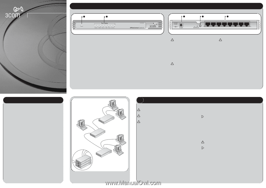
Figure 1
Small Network with OfficeConnect Switch (Circle Shows Units
Clipped Together).
Safety Information
WARNING:
Please read the ‘Important Safety Information’ section in the
Support and Safety Information sheet before you start.
VORSICHT:
Bitte lesen Sie den Abschnitt ‘Wichtige Sicherheitsinformationen’
sorgfältig durch, bevor Sie das Gerät einschalten.
AVERTISSEMENT:
Veuillez lire attentivement la section "Consignes
importantes de sécurité" avant de mettre en route.
When positioning your Switch, ensure:
●
It is out of direct sunlight and away from sources of heat.
●
Cabling is away from power lines, fluorescent lighting fixtures, and sources
of electrical noise such as radios, transmitters and broadband amplifiers.
●
Water or moisture cannot enter the case of the unit.
●
Air flow around the unit and through the vents in the side of the case is
not restricted. We recommend you provide a minimum of 25mm (1in.)
clearance.
Using the Rubber Feet
Use the four self-adhesive rubber feet to prevent your Switch from moving
around on your desk or when stacking with other flat top OfficeConnect
units. Only stick the feet to the marked areas at each corner of the underside
of your Switch.
Using a Stacking Clip
Use a stacking clip when stacking your Switch with curved OfficeConnect
units. Stacking clips are only supplied with curved OfficeConnect units. The
stacking clip allows you to stack units neatly and securely. Refer to user guide
of the curved unit for more details on how to use the stacking clip.
Wall Mounting
There are two slots on the underside of the OfficeConnect Switch that can be
used for wall mounting. 3Com recommends that you mount the Switch with
the LEDs facing upwards to prevent dust entering the ports.
When wall mounting the unit, ensure that it is within reach of the power
outlet.
You need two suitable screws. Ensure that the wall you are going to use is
smooth, flat, dry and sturdy. Make two screw holes which are 150mm (5.9in.)
apart. Fix the screws into the wall, leaving their heads 3mm (0.12in.) clear of
the wall surface.
Remove any connections to the Switch and locate it over the screw heads.
When in line, gently push the Switch on to the wall and move it downwards
to secure. When making connections, be careful not to push the Switch up
and off the wall.
CAUTION:
Only wall mount single units, do not wall mount stacked
units.
Also available from 3Com, is the OfficeConnect Mounting Unit (part
number 3C16765). This allows you to firmly secure a stack of
OfficeConnect devices to the desktop or onto a shelf in a rack.
WARNING: RJ-45 Ports
These are shielded RJ-45 data sockets. They cannot
be used as standard traditional telephone sockets,
or to connect the unit to a traditional PBX or public
telephone network. Only connect RJ-45 data
connectors, network telephony systems, or network
telephones to these sockets. Either shielded or
unshielded data cables with shielded or unshielded
jackets can be connected to these data sockets.
AVERTISSEMENT : Points d’accès RJ-45
Prises RJ-45 blindées. Ces prises ne peuvent servir
comme prises téléphone standard et ne permettent
pas la connexion de l'appareil à un système PBX ni à
un réseau téléphonique public. N'y branchez que
des prises RJ-45 mâles adaptées, ou des systèmes de
réseaux téléphoniques. Il est possible d'y brancher
des câbles blindés ou non comportant des prises de
type Jack (blindées ou non).
VORSICHT: RJ-45-Porte
RJ-45-Portes. Diese Portes sind geschützte
Datensteckdosen. Sie dürfen weder wie normale
traditionelle Telefonsteckdosen noch für die
Verbindung der Einheit mit einem traditionellenm
privatenm oder öffentlichenm Telefonnetzwerk
gebraucht werden. Nur RJ-45-Datenansclußhlüsse,
Telefonnetzsysteme oder Netztelefone an diese
Steckdosen anschließen. Entweder geschützte oder
ungeschützte Buchsen dürfen an diese
Datensteckdosen angeschlossen werden.
1
Power LED
green
Indicates that the Switch is powered on.
2
Five or Eight Port Status LEDs
green (100Mbps link) / yellow (10Mbps link)
If the LED is on, the link between the port and the
next piece of network equipment is OK. If the LED is
flashing, the link is OK and data is being transmitted
or received. If the LED is off, nothing is connected, or
the connected device is switched off, or there is a
problem with the connection (refer to the "Problem
Solving" section).
3
Power Adapter socket
Only use the power adapter that is supplied with
this Switch. Do not use any other adapter.
4
Uplink/Normal switch
Affects the operation of port 8. If you are
connecting another unit (such as a Hub or Switch)
to port 8, set to Uplink (in), otherwise set to Normal
(out). Refer to "Connecting Workstations and Other
Equipment to your Switch".
Note:
For the Switch 5, substitute ‘port 5’ for
‘port 8’.
5
Five or Eight 10/100 ports
Use suitable TP cable with RJ-45 connectors. You
can connect your Switch to a workstation, or any
other piece of equipment that has a 10BASE-T or
100BASE-TX port. Each port is capable of
autosensing for 10Mbps or 100Mbps operation.
Ports operate in half-duplex mode as well as full
duplex mode.
OfficeConnect Switch - Front
OfficeConnect Switch - Rear
Installation Guide