3Com 3C17205 Getting Started Guide
3Com 3C17205 - SuperStack 3 Switch 4400 PWR Manual
 |
UPC - 000064170930
View all 3Com 3C17205 manuals
Add to My Manuals
Save this manual to your list of manuals |
3Com 3C17205 manual content summary:
- 3Com 3C17205 | Getting Started Guide - Page 1
SuperStack® 3 Switch 4400 Series Getting Started Guide Switch 4400 (3C17203) Switch 4400 (3C17204) Switch 4400 PWR (3C17205) Switch 4400 SE (3C17206) Switch 4400 FX (3C17210) http://www.3com.com/ Part No. DUA1720-3AAA06 Published June 2003 - 3Com 3C17205 | Getting Started Guide - Page 2
provided in 3Com's standard commercial license for the Software. Technical User Guide. Unless otherwise indicated, 3Com registered trademarks are registered in the United States and may or may not be registered in other countries. 3Com, the 3Com logo and SuperStack are registered trademarks of 3Com - 3Com 3C17205 | Getting Started Guide - Page 3
THIS GUIDE Before You Start 7 Release Notes 7 About Your CD-ROM 8 Conventions 8 Related Documentation 9 Accessing Online Documentation 10 Documentation Comments 10 Product Registration 11 1 INTRODUCING THE SUPERSTACK 3 SWITCH 4400 About the Switch 4400 14 Summary of Hardware Features 14 Switch 4400 - 3Com 3C17205 | Getting Started Guide - Page 4
4400, 4400 SE and 4400 PWR) 32 Choosing the Correct Cables (Switch 4400 FX) 33 3 SETTING UP FOR MANAGEMENT Setting Up Overview 36 IP Configuration 37 Preparing for Management 38 Manually Setting Up SNMP Management 53 Pre-requisites 53 Default Users and Passwords 54 Changing Default Passwords 54 - 3Com 3C17205 | Getting Started Guide - Page 5
Switch 4400 (24-port) and Switch 4400 SE 75 Switch 4400 PWR (24-port) 77 Switch 4400 (48-port) 78 Switch 4400 FX 79 D TECHNICAL SUPPORT Online Technical Services 81 World Wide Web Site 81 3Com Knowledgebase Web Services 82 3Com FTP Site 82 Support from Your Network Supplier 82 Support from 3Com - 3Com 3C17205 | Getting Started Guide - Page 6
INDEX REGULATORY NOTICES - 3Com 3C17205 | Getting Started Guide - Page 7
and use the following switches in their default state: ■ SuperStack® Switch 4400 (3C17203) ■ SuperStack® Switch 4400 (3C17204) ■ SuperStack® Switch 4400 PWR (3C17205) ■ SuperStack® Switch 4400 SE (3C17206) ■ SuperStack® Switch 4400 FX (3C17210) All procedures described in this guide apply to all - 3Com 3C17205 | Getting Started Guide - Page 8
the following: ■ Online documentation for the Switch 4400 - refer to Related Documentation on page 9 for details. ■ 3Com Network Supervisor - a powerful and easy-to-use network management platform. ■ A number of other useful applications. Most user guides and release notes are available in Adobe - 3Com 3C17205 | Getting Started Guide - Page 9
, and software button names. Examples: From the Help menu, select Contents. Click OK. In addition to this guide, each Switch documentation set includes the following: ■ SuperStack 3 Switch Implementation Guide This guide contains information on the features supported by your Switch and how - 3Com 3C17205 | Getting Started Guide - Page 10
10 ABOUT THIS GUIDE These notes provide information about the current software release, including new features, modifications, and known problems. The Release Notes are supplied in hard copy with your Switch. There are other publications you may find useful, such as: ■ Documentation accompanying - 3Com 3C17205 | Getting Started Guide - Page 11
appropriate) Example: Part Number DUA1720-3AAA06 SuperStack 3 Switch 4400 Series Getting Started Guide Page 21 Please note that we can only respond to comments and questions about 3Com product documentation at this e-mail address. Questions related to technical support or sales should be directed in - 3Com 3C17205 | Getting Started Guide - Page 12
12 ABOUT THIS GUIDE - 3Com 3C17205 | Getting Started Guide - Page 13
THE SUPERSTACK 3 SWITCH 4400 This chapter contains introductory information about the Switch 4400 and how it can be used in your network. It covers summaries of hardware and software features and also the following topics: ■ About the Switch 4400 ■ Switch 4400 - Front View Detail ■ Switch 4400 - 3Com 3C17205 | Getting Started Guide - Page 14
modules are installed in the expansion slots on the rear of the unit. You can also add the Switch 4400 to any SuperStack® system as your network grows. The Switch 4400 PWR (3C17205) supports Power over Ethernet on all front panel ports. If you plug in a compatible (IEEE 802.3af compliant) device - 3Com 3C17205 | Getting Started Guide - Page 15
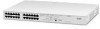
Switch 4400 - Front View Detail 15 Switch 4400 - Front View Detail Figure 1 Switch 4400 FX - front view Figure 2 Switch 4400 (24-port) / Switch 4400 SE - front view Figure 3 Switch 4400 PWR - front view - 3Com 3C17205 | Getting Started Guide - Page 16
SUPERSTACK 3 SWITCH 4400 Figure 4 Switch 4400 The Switch 4400, 4400 SE and 4400 PWR manually set these ports to 10BASE-T half duplex, 10BASE-T full duplex, 100BASE-TX half duplex or 100BASE-TX full duplex. The maximum segment length is 100 m (328 ft) over Category 5 twisted pair cable. The 4400 PWR - 3Com 3C17205 | Getting Started Guide - Page 17
on using the LEDs for problem solving, see "Solving Problems Indicated by LEDs" on page 56. Table 4 LED behavior LED Color Indicates Power/Self Test LED Green The Switch is powered-up and operating normally. Green flashing The Switch is either downloading software or is initializing (which - 3Com 3C17205 | Getting Started Guide - Page 18
(48-port) Green flashing The Switch physically forms a stack with other Switch 4400 units, but cannot be managed as part of that stack until all units have been upgraded to software version 2.0 or later. Off A fault has occurred. Port LED Status LED (3C17205 only) Green Port LEDs are - 3Com 3C17205 | Getting Started Guide - Page 19
Socket to connect a Switch 4400 to a SuperStack 3 Advanced Redundant Power System Switch. For example you can install a Cascade module to enable the Switch to be stacked with other Switches. Please note that Power over Ethernet is not supported on expansion modules on the Switch 4400 PWR (3C17205 - 3Com 3C17205 | Getting Started Guide - Page 20
THE SUPERSTACK 3 SWITCH 4400 Default Settings WARNING: When an Expansion Module is not installed, ensure the blanking plate is fitted by tightening all screws with a suitable tool. Table 5 shows the default settings for the Switch 4400: Table 5 Default Settings Feature Switch 4400 Automatic - 3Com 3C17205 | Getting Started Guide - Page 21
Default Settings 21 To make Webcache Support, Traffic Prioritization and Configuration Save and Restore available on the SuperStack 3 Switch 4400 SE, upgrade the product to the Switch 4400 SE Enhanced Software Upgrade (3C17207). If you initialize a Switch unit by selecting System > Control > - 3Com 3C17205 | Getting Started Guide - Page 22
22 CHAPTER 1: INTRODUCING THE SUPERSTACK 3 SWITCH 4400 - 3Com 3C17205 | Getting Started Guide - Page 23
informations relatives à la sécurité qui se trouvent dans l'Appendice A de ce guide. VORSICHT: Sicherheitsinformationen. Bevor Sie Komponenten aus dem Switch 4400 entfernen oder dem Switch 4400 hinzufuegen oder Instandhaltungsarbeiten verrichten, lesen Sie die Sicherheitsanweisungen, die in Appendix - 3Com 3C17205 | Getting Started Guide - Page 24
24 CHAPTER 2: INSTALLING THE SWITCH Package Contents ■ Switch unit ■ CD-ROM (includes documentation related to your Switch) ■ Getting Started Guide (this guide) ■ Management Quick Reference Guide ■ Release Notes ■ Unit Information Labels ■ Warranty Information ■ Power Cord ■ 2 x Mounting brackets - 3Com 3C17205 | Getting Started Guide - Page 25
generate high levels of AC noise, for example air conditioning units and laser printers. Rack-mounting The Switch 4400 is 1U high and will fit in most standard 19-inch racks. CAUTION: Disconnect all cables from the Switch before continuing. Remove all self adhesive pads from the underside of the - 3Com 3C17205 | Getting Started Guide - Page 26
incorrect screws invalidates your warranty. 4 Repeat steps 2 and 3 for the other side of the Switch. 5 Insert the Switch into the 19-inch 3Com product name of the Switch ■ The 3Com 3C number of the Switch ■ The unique MAC address (Ethernet address) of the Switch ■ The serial number of the Switch - 3Com 3C17205 | Getting Started Guide - Page 27
-port Switches The SuperStack 3 Switch 4400 SE can only be stacked with non-SE Switches if it has been upgraded using the Switch 4400 SE Enhanced Software Upgrade (3C17207). An upgraded Switch 4400 SE cannot be stacked with a normal Switch 4400 SE. How To Stack Units To stack two Switch 4400 units - 3Com 3C17205 | Getting Started Guide - Page 28
28 CHAPTER 2: INSTALLING THE SWITCH Figure 7 Stacking two Switch 4400 units 3C17224 Module 2 UP SuperStack 3 Cascade Module 3C17224 Module 2 DOWN SuperStack 3 Cascade Module Switch 2 Switch 1 To stack more than two Switch units you will need to order one SuperStack 3 Cascade Extender Kit ( - 3Com 3C17205 | Getting Started Guide - Page 29
stack to the latest software agent. ■ 3Com recommends that you initialize a Switch 4400, Switch 4400 SE, Switch 4400 PWR or Switch 4400 FX unit that has previously been used elsewhere in your network before you add it to an existing stack. If you do not initialize the unit, problems may be caused by - 3Com 3C17205 | Getting Started Guide - Page 30
normal redundancy, the Switch 4400, Switch 4400 SE, and Switch 4400 FX require one Type 2A Power Module (3C16074A). For full redundancy, the Switch 4400, Switch 4400 SE, and Switch 4400 FX require two type 2A Power Modules combined using a Type 2 Y-Cable. The Switch 4400 PWR (3C17205) requires one - 3Com 3C17205 | Getting Started Guide - Page 31
power cord. CAUTION: The Switch can only use a SuperStack Advanced Redundant Power System output. Using Power over Ethernet The Switch 4400 PWR can power any IEEE 802.3af compliant device through any of its front panel ports. The Switch will support the following 3Com 802.3af equipment: ■ Wireless - 3Com 3C17205 | Getting Started Guide - Page 32
PWR (3C17205) supports Power over Ethernet on all front ports. These ports should only be used for ethernet wiring within the same building. The Rear Module ports of the Switch 4400 PWR can be used for ethernet wiring between buildings. 3Com recommends that you use Category 5 twisted pair cable - 3Com 3C17205 | Getting Started Guide - Page 33
4400 to other devices if auto-negotiation is disabled Cross-over Cable Switch to Switch (MDIX to MDIX) ✓ Switch to Hub ✓ (MDIX to MDIX) Switch to PC (NIC) ✕ (MDIX to MDI) Straight-through Cable ✕ ✕ ✓ CAUTION: If you want to install the Switch using a Category 5E or Category 6 cable, 3Com - 3Com 3C17205 | Getting Started Guide - Page 34
34 CHAPTER 2: INSTALLING THE SWITCH - 3Com 3C17205 | Getting Started Guide - Page 35
topics: ■ Setting Up Overview ■ Manually Configuring IP Information ■ Viewing Automatically Configured IP Information ■ Methods of Managing a Switch ■ Setting Up Command Line Interface Management ■ Setting Up Web Interface Management ■ Setting Up SNMP Management ■ Default Users and Passwords - 3Com 3C17205 | Getting Started Guide - Page 36
ready for management when it is in its default state. The whole setup process is summarized in Figure 9. Detailed procedural steps are contained in the sections that follow. In brief, you need to: ■ Configure IP information manually for your Switch or view the automatically configured IP information - 3Com 3C17205 | Getting Started Guide - Page 37
from unauthorized access, you must change all three default passwords as soon as possible, even if you do not intend to actively manage your Switch. For more information on default users and changing default passwords, see "Default Users and Passwords" on page 54. IP Configuration You can use one - 3Com 3C17205 | Getting Started Guide - Page 38
Managing a Switch" on page 49. For detailed information about the specific web interface operations and command line interface commands and problem solving, refer to the "SuperStack 3 Switch Management Interface Reference Guide" on the CD-ROM that is supplied with the Switch or on the 3Com Web site - 3Com 3C17205 | Getting Started Guide - Page 39
manually you can make a connection to a front Panel Port panel port. You must do this whilst the Switch is offline, that is, before you connect the Switch to a network. The procedure described in this section assumes the unit has been powered up in standalone mode and has the default IP address - 3Com 3C17205 | Getting Started Guide - Page 40
the existing settings so you can return to them later. Change the workstation to the following settings: ■ IP address - 169.254.100.99 ■ Subnet mask - 255.255.0.0 Setting Up the Switch with IP Information You are now ready to manually set up the Switch with IP information. You can do this using the - 3Com 3C17205 | Getting Started Guide - Page 41
name and press Return at the password prompt (default user name and password). If you have logged on correctly, a set of Getting Started pages are displayed. 4 The Getting Started pages allow you to enter basic setup information for the Switch. Select Manual and then enter the IP address, subnet - 3Com 3C17205 | Getting Started Guide - Page 42
passwords, and then given the option to carry out advanced configuration. The initial set up of your Switch is now complete and the Switch is . See "Methods of Managing a Switch" on page 49. Connecting to the Console Port To set up your Switch manually you can alternatively make a connection - 3Com 3C17205 | Getting Started Guide - Page 43
in Appendix B on page 71. ■ You need to have the following so that you can manually set up the Switch with IP information: ■ IP address ■ subnet mask ■ default gateway Connecting the Workstation to the Switch 1 Connect the workstation to the console port using a standard null modem cable as shown in - 3Com 3C17205 | Getting Started Guide - Page 44
44 CHAPTER 3: SETTING UP FOR MANAGEMENT 2 Open your terminal emulation software and configure the COM port settings to which you have connected the cable. The settings should be set to match the default settings for the Switch, which are: ■ 19,200 baud ■ 8 data bits ■ no parity ■ 1 stop bit ■ no - 3Com 3C17205 | Getting Started Guide - Page 45
the protocol ip basicConfig command. At the Enter configuration method prompt enter manual. The screen prompts you to enter IP information. or ■ enter change passwords, and then given the option to carry out advanced configuration. The initial set up of your Switch is now complete and the Switch is - 3Com 3C17205 | Getting Started Guide - Page 46
the automatically allocated IP information. 1 Connect your Switch to the network. 2 Power-up the Switch and wait for two minutes. 3 Launch 3Com Network Supervisor and run the Auto-discovery wizard. 3Com Network Supervisor will auto-discover the new Switch and display the IP information that has been - 3Com 3C17205 | Getting Started Guide - Page 47
one of the serial ports (also known as a COM port) on your workstation. 2 Open your terminal emulation software and configure the COM port settings to which you have connected the cable. The settings should be set to match the default settings for the Switch, which are: ■ 19,200 baud ■ 8 data bits - 3Com 3C17205 | Getting Started Guide - Page 48
sequence begins as soon as the Switch detects a connection to its console port. If the login prompt does not begin immediately, press Return a few times until it starts. 3 At the login and password prompts, enter admin as your user name and press Return at the password prompt. If you have logged on - 3Com 3C17205 | Getting Started Guide - Page 49
can logout, disconnect the serial cable and close the terminal emulator software. Methods of Managing a Switch Once you have completed the initial set up of your Switch, you can decide how you wish to manage the Switch. You can use one of the following methods: ■ Command line interface management - 3Com 3C17205 | Getting Started Guide - Page 50
the Simple Network Management Protocol (SNMP) as shown in Figure 19. For example, you can use the 3Com Network Supervisor software that is provided on the CD-ROM that accompanies your Switch. Figure 19 SNMP management over the network Refer to "Setting Up SNMP Management" on page 53. Setting - 3Com 3C17205 | Getting Started Guide - Page 51
IP address of the Switch) If opening a Telnet session via third party software you will need to enter the IP address in the format suitable for that software. 5 At the login and password prompts, enter admin as your user name and press Return at the password prompt (or the password of your choice if - 3Com 3C17205 | Getting Started Guide - Page 52
Switch is connected to the network using a Category 5 twisted pair Ethernet cable with RJ-45 connectors. ■ A suitable Web browser. Choosing a Browser To display the web interface correctly, use one of the following Web browser and platform combinations: Table 8 Supported by default. You open - 3Com 3C17205 | Getting Started Guide - Page 53
of the Switch that you wish to manage in the URL locator, for example, in the following format: http://xxx.xxx.xxx.xxx 4 At the login and password prompts, enter admin as your user name and press Return at the password prompt (or the password of your choice if you have already modified the default - 3Com 3C17205 | Getting Started Guide - Page 54
snmp community command - refer to the command line interface section of the "SuperStack 3 Switch Management Interface Reference Guide" for more information. Default Users and Passwords If you intend to manage the Switch using the web interface or the command line interface, or to change the - 3Com 3C17205 | Getting Started Guide - Page 55
Indicated by LEDs ■ Solving Hardware Problems ■ Solving Communication Problems ■ Solving Software Upgrade Problems If you experience a problem that is not listed here, it may be included in the Support section of the Superstack 3 Switch Management Interface Reference Guide on the CD-ROM that - 3Com 3C17205 | Getting Started Guide - Page 56
device then contact your supplier for advice. On powering-up, the Power/Self Test LED lights yellow Either: ■ The Switch unit has failed its Power On Self Test (POST) because of an internal problem. The fault type will be indicated on the unit LEDs. Contact your supplier for advice. or ■ A port has - 3Com 3C17205 | Getting Started Guide - Page 57
cross-over or straight) Auto-negotiation problems will occur with fiber if: software version 2.0 or later. You must upgrade each unit in the stack to this software version, which is available on the CD-ROM that accompanies your Switch. Port LED Status LED is flashing yellow (3C17205 only) The Switch - 3Com 3C17205 | Getting Started Guide - Page 58
of the fan failure via email, SMS (Short Message Service), or pager. ■ RMON Trap - If configured, an RMON trap is generated and sent to the management workstation. For further information about RMON, refer to "Chapter 7: Status Monitoring and Statistics" in the Switch Implementation Guide supplied - 3Com 3C17205 | Getting Started Guide - Page 59
Problems 59 Unit fails, no SNMP fan 3Com. A device is connected to a Switch 4400 PWR but power is not being supplied If power is not being supplied to a device connected to a Switch 4400 PWR Switch have equal priority levels, then the port with the highest number will lose power. By default the Switch - 3Com 3C17205 | Getting Started Guide - Page 60
problems with the Switch, ensure that: ■ The Switch IP address has been configured as described in Chapter 3. ■ If the Switch is separated from your management application by a router, ensure that the default gateway IP address within the Switch . InterNIC Registration Services is the organization - 3Com 3C17205 | Getting Started Guide - Page 61
the command line interface. For details on these options, refer to the Management Interface Reference Guide supplied in HTML format on the CD-ROM that accompanies your Switch. If you have problems with your software upgrade, refer to the Problem Solving section in the Management Interface Reference - 3Com 3C17205 | Getting Started Guide - Page 62
62 CHAPTER 4: PROBLEM SOLVING - 3Com 3C17205 | Getting Started Guide - Page 63
must read the following safety information before carrying out any installation or removal of components, or any maintenance procedures on the Switch 4400. WARNING: Warnings contain directions that you must follow for your personal safety. Follow all directions carefully. You must read the following - 3Com 3C17205 | Getting Started Guide - Page 64
of the unit must be carried out by qualified personnel only. WARNING: If installing the Switch 4400 in a stack with SuperStack II or SuperStack 3 units that are narrower than the 4400, the Switch 4400 unit must be installed below the narrower units. WARNING: The unit must be earthed (grounded - 3Com 3C17205 | Getting Started Guide - Page 65
labelled Neutral, connected directly to earth (ground). †Impédance à la terre. WARNING: U.K. only: If connecting a modem to the console port of the Switch 4400, only use a modem which is suitable for connection to the telecommunications system. WARNING: RJ-45 Ports. These are shielded RJ-45 data - 3Com 3C17205 | Getting Started Guide - Page 66
66 APPENDIX A: SAFETY INFORMATION WARNING: The 4400 PWR (3C17205) supports Power over Ethernet on all front ports à un personnel qualifié. AVERTISSEMENT: Si vous entassez l'unité Switch avec les unités SuperStack 3 Hub, l'unité Switch 4400 doit être installée en dessous des unités Hub plus é - 3Com 3C17205 | Getting Started Guide - Page 67
L'information de Sécurité Importante 67 Europe Suisse ■ La prise secteur doit être conforme aux normes CEE 7/7 ("SCHKO") ■ LE cordon secteur doit porter la mention ou et doit être de type HO3VVF3GO.75 (minimum). ■ La prise mâle d'alimentation doit respecter la norme SEV/ASE 1011 - 3Com 3C17205 | Getting Started Guide - Page 68
bles à fibres optiques tant qu'ils sont sous tension. AVERTISSEMENT: Le 4400 PWR (3C17205) prend en charge la mise sous tension par Ethernet au niveau de Wenn die Switch 4400 Einheit in einer Stapel mit anderen SuperStack 3 Hub Einheiten eingebaut werden soll, muß die Switch 4400 Einheit unter die - 3Com 3C17205 | Getting Started Guide - Page 69
Wichtige Sicherheitsinformationen 69 VORSICHT: Der Gerätestecker (der Anschluß an das Gerät, nicht der Wandsteckdosenstecker) muß eine passende Konfiguration für einen Geräteeingang gemäß EN60320/IEC320 haben. VORSICHT: Die Netzsteckdose muß in der Nähe des Geräts und leicht zugänglich sein. Die - 3Com 3C17205 | Getting Started Guide - Page 70
ist. Niemals direkt auf den Faser-TX-Anschluß und auf die Faserkabelenden schauen, während diese eingeschaltet sind. VORSICHT: Das 4400 PWR (3C17205) unterstützt die Stromversorgung per Ethernet an allen vorderen Ports. Diese Ports dürfen nur für die Ethernet-Verkabelung im gleichen Geb - 3Com 3C17205 | Getting Started Guide - Page 71
B PIN-OUTS Null Modem Cable 9-pin to RS-232 25-pin PC-AT Serial Cable 9-pin to 9-pin - 3Com 3C17205 | Getting Started Guide - Page 72
72 APPENDIX B: PIN-OUTS Modem Cable 9-pin to RS-232 25-pin RJ-45 Pin Assignments Pin assignments are identical for 10BASE-TX and 100BASE-T RJ-45 connectors. Table 10 Pin assignments Pin Number Signal Ports configured as MDI 1 Transmit Data + 2 Transmit Data + 3 Receive Data + 4 Not - 3Com 3C17205 | Getting Started Guide - Page 73
Table 11 Pin assignments Pin Number Signal Ports configured as MDIX 1 Receive Data + 2 Receive Data - 3 Transmit Data + 4 Not assigned 5 Not assigned 6 Transmit Data 7 Not assigned 8 Not assigned RJ-45 Pin Assignments 73 Function Bidirectional Data B+ Bidirectional Data - 3Com 3C17205 | Getting Started Guide - Page 74
74 APPENDIX B: PIN-OUTS - 3Com 3C17205 | Getting Started Guide - Page 75
TECHNICAL SPECIFICATIONS Switch 4400 (24-port) and Switch 4400 SE Physical 104 °F) -40 ° to +70 °C (-40 ° to 158 °F) 10-95% relative humidity, non-condensing EN60068 to 3Com schedule (Package testing: paras 2.1, 2.2, 2.30, and 2.32. Operational testing: paras 2.1, 2.2, 2.30 and 2.13). UL - 3Com 3C17205 | Getting Started Guide - Page 76
76 APPENDIX C: TECHNICAL SPECIFICATIONS Standards Supported SNMP SNMP protocol (RFC 1157) MIB-II (RFC 1213) Bridge MIB (RFC 1493) RMON MIB II (RFC 2021) Remote Monitoring MIB (RFC 1757) MAU MIB ( - 3Com 3C17205 | Getting Started Guide - Page 77
Switch 4400 PWR (24-port) 77 Switch 4400 PWR (24-port) Physical Supported Height: 44 mm (1.7 in.) x Width: 440 mm (17.3 in.) x Depth: 295 mm (11.4 in.) Weight: 4.4 kg (9.7 lbs) 0 ° to 40 °C (32 ° to 104 °F) -20 ° to +70 °C (-4 ° to 158 °F) 10-95% relative humidity, non-condensing EN60068 to 3Com - 3Com 3C17205 | Getting Started Guide - Page 78
Switch 4400 (48-port) Physical Dimensions Environmental Requirements Operating Temperature Storage Temperature Operating Humidity Standards Safety Agency Certifications EMC Emissions Immunity Heat Dissipation Power Supply AC Line Frequency Input Voltage Options Current Rating Standards Supported - 3Com 3C17205 | Getting Started Guide - Page 79
Switch 4400 FX 79 Switch 4400 FX Physical Dimensions Supported Height: 44 mm (1.7 in.) x Width: 440 mm (17.3 in.) x Depth: 274 mm (10.8 in.) Weight: 2.8 kg (6.2 lbs) 0 ° to 40 °C (32 ° to 104 °F) -40 ° to +70 °C (-40 ° to 158 °F) 10-95% relative humidity, non-condensing EN60068 to 3Com - 3Com 3C17205 | Getting Started Guide - Page 80
80 APPENDIX C: TECHNICAL SPECIFICATIONS - 3Com 3C17205 | Getting Started Guide - Page 81
from your network supplier or from 3Com. These services can enhance warranty response times. They can also provide supplementary services not included in your product warranty. These services include telephone support 24 hours a day, 7 days a week, advance shipment of replacement hardware, and - 3Com 3C17205 | Getting Started Guide - Page 82
This service is available 24 hours a day, 7 days a week. To connect to the 3Com FTP site, enter the following information into your FTP client: ■ Hostname: ftp.3com.com ■ Username: anonymous ■ Password: You do not need a user name and password with Web browser software - 3Com 3C17205 | Getting Started Guide - Page 83
://lat.3com.com/br/support/form.html English speakers, e-mail: [email protected] Telephone Support When you contact 3Com for assistance, have the following information ready: ■ Product model name, part number, and serial number ■ A list of system hardware and software, including revision - 3Com 3C17205 | Getting Started Guide - Page 84
list of worldwide technical telephone support numbers. These numbers are correct at the time of publication. Refer to the 3Com Web site for updated information. Country Telephone Number Country Asia, Pacific Rim Australia Hong Kong India Indonesia Japan Malaysia New Zealand Pakistan 1 800 678 - 3Com 3C17205 | Getting Started Guide - Page 85
expense. You can obtain a Return Materials Authorization number (RMA) by entering the following URL into your Internet browser: http://www.3com.com/support/en_US/repair Alternatively, you can obtain an RMA by calling or faxing one of the following numbers: Country Telephone Number Country Asia - 3Com 3C17205 | Getting Started Guide - Page 86
2112 AT&T +800 998 2112 57 1 657 0888 Contacting 3Com Please be aware that to improve quality, 3Com might contact you for Support your view on 3Com customer service. If you do not wish to be contacted, please inform our support representative. Calls may be recorded for training purposes. Any data - 3Com 3C17205 | Getting Started Guide - Page 87
in as a default user 54 M MAC address of the Switch 26 management methods 49 preparing for 38 setting up 35, 36 manual setup console port 42 front panel port 39 MDI configuration 32 MDIX configuration 32 N network supplier support 82 O online technical services 81 P passwords of default users 54 pin - 3Com 3C17205 | Getting Started Guide - Page 88
Switch 4400 30 problem solving 55 communication problems 60 hardware problems 57 IP addressing 57 LEDs 56 product name 26 R rack mounting a Switch 4400 75 T technical support 3Com Knowledgebase Web Services 82 3Com URL 81 network suppliers 82 product repair 85 troubleshooting 55 U unit information - 3Com 3C17205 | Getting Started Guide - Page 89
and, if not installed and used in accordance with the instructions, may cause harmful interference to radio communications. Operation of this user may find the following booklet prepared by the Federal Communications Commission helpful: How to Identify and Resolve Radio-TV Interference Problems - 3Com 3C17205 | Getting Started Guide - Page 90
-
 1
1 -
 2
2 -
 3
3 -
 4
4 -
 5
5 -
 6
6 -
 7
7 -
8
-
9
-
10
-
11
-
12
-
13
-
14
-
15
-
16
-
17
-
18
-
19
-
20
-
21
-
22
-
23
-
24
-
25
-
26
-
27
-
28
-
29
-
30
-
31
-
32
-
33
-
34
-
35
-
36
-
37
-
38
-
39
-
40
-
41
-
42
-
43
-
44
-
45
-
46
-
47
-
48
-
49
-
50
-
51
-
52
-
53
-
54
-
55
-
56
-
57
-
58
-
59
-
60
-
61
-
62
-
63
-
64
-
65
-
66
-
67
-
68
-
69
-
70
-
71
-
72
-
73
-
74
-
75
-
76
-
77
-
78
-
79
-
80
-
81
-
82
-
83
-
84
-
85
-
86
-
87
-
88
-
89
-
90
 |
 |

Part No. DUA1720-3AAA06
Published June 2003
SuperStack
®
3
Switch 4400 Series
Getting Started Guide
Switch 4400 (3C17203)
Switch 4400 (3C17204)
Switch 4400 PWR (3C17205)
Switch 4400 SE (3C17206)
Switch 4400 FX (3C17210)