3Com 3C780 User Guide
3Com 3C780 - LinkBuilder FDDI Base Unit Manual
 |
UPC - 662705029917
View all 3Com 3C780 manuals
Add to My Manuals
Save this manual to your list of manuals |
3Com 3C780 manual content summary:
- 3Com 3C780 | User Guide - Page 1
LinkBuilder® FDDI Workgroup Hub User Guide A member of the LinkBuilder FDDI family For 3Com User Group Information 1-800-NET-3Com or your local 3Com office Manual Part No. 09-0447-000 Published July 1993. Printed in the U.S.A. i - 3Com 3C780 | User Guide - Page 2
United States. Portions of this manual are reproduced in whole or in part with permission from (as appropriate). 3Com and LinkBuilder are registered trademarks of 3Com Corporation. CardFacts, NetFacts, Ask3Com, 3ComFacts, and CardBoard are service marks of 3Com Corporation. Motorola is a registered - 3Com 3C780 | User Guide - Page 3
for software products may be obtained by telephoning 3Com's Corporate Service Center or an Authorized 3Com Service Center, within the warranty period. Products returned to 3Com's Corporate Service Center must be pre-authorized by 3Com with a Return Material Authorization (RMA) number marked on - 3Com 3C780 | User Guide - Page 4
LIABILITY IN CONNECTION WITH THE SALE, INSTALLATION, MAINTENANCE OR USE OF ITS PRODUCTS. 3COM SHALL NOT BE LIABLE UNDER THIS WARRANTY IF ITS TESTING AND EXAMINATION DISCLOSE THAT THE may vary from state to state. 3Com Corporation 5400 Bayfront Plaza Santa Clara, CA 95052-8145 (408) 764-5000 6/15/92 - 3Com 3C780 | User Guide - Page 5
, if not installed and used in accordance with the instructions, may cause harmful interference to radio communications. However, there when connecting to this device. Changes or modifications not expressly approved by 3Com could void the user's authority to operate this equipment. Suggested cable - 3Com 3C780 | User Guide - Page 6
Suppression Requirements of Vfg 1046/1984. The German Postal Service was notified that the equipment is being marketed. The German Postal Service has the right to re-test the equipment and to verify that it complies. 3Com Corporation 5400 Bayfront Plaza Santa Clara, California, U.S.A. 95052-8145 vi - 3Com 3C780 | User Guide - Page 7
Contents Quick Start Road Map to Hub Operations 1 Unpacking the Hub 2 Unpacking the Modules 3 Installing the Modules 4 Connecting to the Ring 6 Chapter 1 Overview FDDI Technology 1-2 Physical Medium Dependent (PMD) Protocol 1-4 Fiber-Optic 1-4 Shielded Twisted Pair (STP) 1-4 Unshielded Twisted Pair - 3Com 3C780 | User Guide - Page 8
Cable 2-20 Unshielded Twisted-Pair Cable 2-21 Data Flow Specifications 2-23 Connecting to the Dual Ring 2-24 Installing an Optical Bypass Switch 2-26 Chapter 3 Configuring the Hub Attachment Options 3-1 Dual Attachment Hub 3-2 Single Attachment Hub 3-4 Null Attachment Hub 3-5 Dual Homing 3-6 Default - 3Com 3C780 | User Guide - Page 9
Port Connections 3-11 Configuring Modules 3-15 Using the STP Cascade Connector 3-18 Chapter 4 Setting Up the Hub Commands 4-1 Command Descriptions 4-2 Display of Command Results 4-2 Setting Addresses 4-3 IP Address 4-3 Netmask 4-4 Broadcast Address 4-4 Default Gateway Address 4-4 Setting the - 3Com 3C780 | User Guide - Page 10
LOW BATT LED 5-14 Dangerous Environmental Conditions Display 5-14 RESET Function 5-15 Media Module LEDs 5-16 Using Miscellaneous Commands 5-17 Diagnosing Network Problems 5-17 ping Command 5-18 route Command 5-19 arp Command 5-20 show log and clear log Commands 5-21 Using Connectivity Commands 5-22 - 3Com 3C780 | User Guide - Page 11
Appendix A System Messages Error Messages A-1 Download Messages A-4 Fault Log Error Code Messages A-6 Appendix B Technical Specifications Appendix C Commands Management Console Commands C-1 Set Commands C-1 set attach C-1 set baud C-2 set boot C-3 set gateway C-4 set help C-4 set ip C-4 set ler C-5 - 3Com 3C780 | User Guide - Page 12
show sid C-14 show tmax C-14 show tneg C-15 show tnotify C-15 show treq C-15 show tvx C-15 Diagnostic and Connectivity Commands arp C-16 clear C-16 connect C-17 disconnect C-17 help C-17 logout C-17 ping C-18 reset C-18 route C-18 Primitive Console Commands C-19 Set Commands C-20 set attach C-20 set - 3Com 3C780 | User Guide - Page 13
22 clear C-22 help | ? C-22 reset C-22 Appendix D Technical Support On-line Product Support D-1 CardBoard Bulletin Board Service D-1 Automated Fax Service D-2 Ask3Com On-line Service D-2 3Com Documentation on CD-ROM D-3 Support from Your Network Supplier D-3 U.S. and Canada D-3 Outside the U.S. and - 3Com 3C780 | User Guide - Page 14
Panel 1-14 2-1. Attaching Mounting Brackets to the Hub 2-3 2-2. LinkBuilder FDDI Workgroup Hub Installed in a Distribution Rack 2-4 2-3. Battery Location Hub and Stations 2-24 2-10. Optical Bypass Switch 2-26 2-11. Cabling for Installing an Optical Bypass Switch 2-27 2-12. Rack Mounting a Hub with - 3Com 3C780 | User Guide - Page 15
3-1. Dual Attachment Hub (DAC) 3-2 3-2. Dual Attachment Hubs (DACs) in Wrap State 3-3 3-3. Single Attachment Hub (SAC) 3-4 3-4. Null Attachment Hub (NAC) and Connected Stations (SAS and DAS) 3-5 3-5. Dual Homing Connections 3-6 3-6. Upstream and Downstream Neighbors 3-13 3-7. Using Two STP Cascade - 3Com 3C780 | User Guide - Page 16
Tables 2-1. DB-9 STP Connector Pin Assignments 2-21 2-2. RJ-45 UTP Connector Pin Assignments 2-22 2-3. FDDI Port Types 2-23 3-1. LinkBuilder FDDI Workgroup Hub Default Configuration 3-7 3-2. Selecting Port Configurations for Attachment Types 3-12 3-3. Port Connection Rules 3-14 3-4. Definitions for - 3Com 3C780 | User Guide - Page 17
3Com's FDDI Training and ® Reference Manual Understanding FDDI (3CS-360) is a pragmatic independent study course and reference manual written for professionals involved in the design, implementation, or support 3Com interprets the FDDI standards to provide tangible and ® LinkBuilder to guide and - 3Com 3C780 | User Guide - Page 18
BATT M/M WAN Technologies for Internetworking (3CS-370) Order through your authorized 3Com reseller or local 3Com office. Availability in self-study format may vary outside the U.S. To order directly from 3Com Education Services, call 1-800-876-3266, press option 7, then option 3. Callers outside - 3Com 3C780 | User Guide - Page 19
Chapter Title 1-1 ® wants to hear from you! To ensure the very best 3Com service and support, take advantage of our One-Year Warranty on 3Com's LinkBuilder® FDDI Workgroup Hub. Please fill out and return the enclosed registration card to start your one-year warranty period. - 3Com 3C780 | User Guide - Page 20
Mediterraneo Srl, Marketing Department Via Michelangelo Buonarroti 1 20093 Cologno Monzese (MI) Milano Italia s United Kingdom, Eire 3Com UK Ltd., Marketing Department Pacific House Third Avenue, Globe Park Marlow-on-Thames Buckinghamshire, SL7 1YW United Kingdom s Sweden, Finland, Norway, Denmark - 3Com 3C780 | User Guide - Page 21
to Hub Operations The steps listed below summarize the procedures needed to make the 3Com® LinkBuilder® FDDI Workgroup Hub operational. The list also shows where each step is discussed in this user guide. 1. Unpacking the hub and modules - Quick Start - Chapter 2: "Unpacking the Hub"; "Installing - 3Com 3C780 | User Guide - Page 22
packing list, and inspect each item for damage. The basic package includes the following items: s LinkBuilder FDDI Workgroup Hub (base unit) s LinkBuilder FDDI Workgroup Hub User Guide s LinkBuilder FDDI System Software diskette, version 1.0 s Standard ac power cord s Two brackets and eight screws - 3Com 3C780 | User Guide - Page 23
Quick Start 3 The LinkBuilder FDDI System Software diskette, version 1.0, contains a readme file and a an STP media port module, one cascade connector will be shipped with the module. For complete instructions on installing the hub, the modules, and the battery, see Chapter 2, "Installing the Hub." - 3Com 3C780 | User Guide - Page 24
between modules. When you install the management module for the first time, be sure that power to the hub is off. There is no power switch on the hub. Power to the hub is provided by connecting the power cord to the hub and to an ac outlet. NOTE: The hub - 3Com 3C780 | User Guide - Page 25
Quick Start 5 To install the modules, follow these steps: 1. Remove all jewelry from your hands and wrists. 2. If necessary, remove blanking plates from the module slots. Keep the removed blanking plates in a safe place for possible future use. 3. Remove the module from its antistatic bag. Prepare a - 3Com 3C780 | User Guide - Page 26
6 Quick Start Connecting to the Ring After installing the modules and plugging in the power cord, you are ready to connect the hub to the ring by attaching the appropriate cables to the attachment ports, which are the two leftmost ports on the module installed in slot 1. To complete the connection - 3Com 3C780 | User Guide - Page 27
3Com® LinkBuilder® FDDI Workgroup Hub brings Fiber Distributed Data Interface (FDDI) high-speed LAN technology to the desktop. (Throughout this guide, the LinkBuilder FDDI Workgroup Hub will be referred to as "the hub.") The hub supports with National Semiconductor® Corporation's BMAC (FDDI Media - 3Com 3C780 | User Guide - Page 28
of flash memory s 128 KB of RAM for frame buffer and descriptors This guide is intended for network installers and operators who are familiar with FDDI technology and 3Com Education Services.) FDDI Technology FDDI technology is an American National Standards Institute (ANSI) standard that supports - 3Com 3C780 | User Guide - Page 29
Ring wrap Overview 1-3 Break in ring or station failure Ring wrap Primary ring Secondary ring Figure 1-1. Ring Wrap The FDDI standard developed by the American National Standards Institute (ANSI) defines four protocols: s Physical Medium Dependent (PMD) s Physical (PHY) s Media Access Control (MAC - 3Com 3C780 | User Guide - Page 30
is invoked when an FDDI station is powered off. (For information on the optical bypass switch, see Chapter 2, "Installing the Hub.") The PMD services included for each type of media supported by the LinkBuilder FDDI Workgroup Hub are listed below. Fiber-Optic The PMD standard provides these - 3Com 3C780 | User Guide - Page 31
Overview 1-5 Unshielded Twisted Pair (UTP) The ANSI TP-PMD standard provides these services for UTP: s Cable requirements for category 5 UTP as defined by EIA/TIA-568 s Electrical requirements for UTP transceivers s FDDI-UTP cable connector Physical (PHY) Protocol - 3Com 3C780 | User Guide - Page 32
station activities s Ring maintenance s Ring initialization, control, and performance Features and Functions The LinkBuilder FDDI Workgroup Hub performs the following tasks in an FDDI network: s Connects end stations, bridges, routers, and other FDDI devices as well as additional hubs to the network - 3Com 3C780 | User Guide - Page 33
: - FDDI media port module supporting 62.5/125 µm fiber-optic cable per the ANSI FDDI standard - STP media port module supporting shielded twisted-pair (STP) type attachment, single attachment, null attachment, and dual homing. s Serviceability with power-on insertion. You can insert and remove the - 3Com 3C780 | User Guide - Page 34
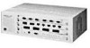
ERROR ® OPTICAL BYPASS SERIAL PORT ATTACH MANAGEMENT MODULE B/A FAN HI LOW ® PWR RESET S/M STATUS TOKEN WRAP FAIL TEMP BATT M/M Figure 1-2. The LinkBuilder FDDI Workgroup Hub Site Selection The hub is housed in a 16.8 x 11.6 x 5.2 inch chassis that can be placed on a tabletop or - 3Com 3C780 | User Guide - Page 35
attachment hubs (DAC) are connected to the trunk ring. s Two single attachment stations (SAS) are connected to each of the hubs. NOTE: 3Com uses the standard acronym DAC (for dual attachment concentrator) shown above but calls the concentrator a hub rather than a concentrator. DAS 1 DAS 2 DAC - 3Com 3C780 | User Guide - Page 36
1-10 Overview The most common "FDDI to the desktop" configuration is the ring of trees topology, shown in Figure 1-4. This figure illustrates the connecting of stations using a hub to form a tree-like structure that branches off the main trunk ring. DAS DAS DAC SAC SAC SAS SAS Figure 1-4. - 3Com 3C780 | User Guide - Page 37
media modules, see Chapter 5, "Using the Hub.") Management Module The LinkBuilder FDDI Management Module, hereafter called the "management module," must be inserted a 6-pin mini-DIN receptacle for the connection to an optical bypass switch (OBS). GRN = SIGNAL DETECT GRN = PORT STATE YEL = LINK - 3Com 3C780 | User Guide - Page 38
s LinkBuilder FDDI 4-port Optic Module (fiber media port module) s LinkBuilder FDDI 6-port STP Module (STP media port module) s LinkBuilder FDDI and M, or M and M as necessary to support a given attachment. (Refer to Chapter 4 for instructions for configuring the attachment ports.) The remaining two - 3Com 3C780 | User Guide - Page 39
Overview 1-13 GRN = SIGNAL DETECT GRN = PORT STATE YEL = LINK ERROR ® PWR FIBER PORT MODULE Figure 1-6. Fiber Media Port Module, Front Panel If you insert the module in slots 2 or 3, all ports are automatically configured as M ports. With three fiber modules installed in the hub, 12 fiber MIC - 3Com 3C780 | User Guide - Page 40
1-14 Overview STP Media Port Module Figure 1-8 shows the front panel of the six-port STP media port module. All of its ports are configured as M ports by default. You can specify any port configuration for the attachment ports, but you must use a special connector called the STP cascade connector - 3Com 3C780 | User Guide - Page 41
Hub This chapter describes installation of the LinkBuilder FDDI Workgroup Hub. It includes the Understanding data flow s Installing an optional optical bypass switch NOTE: For a step-by-step procedure for Quick Start chapter at the beginning of this guide. Unpacking the Hub To unpack the hub, - 3Com 3C780 | User Guide - Page 42
involves installing mounting brackets onto the hub and mounting the hub in the rack. To mount the hub in a 19-inch distribution rack, follow these instructions: 1. Lift the hub from its packing container and place it on a table or other flat surface. You should get help lifting the hub; it weighs - 3Com 3C780 | User Guide - Page 43
Installing the Hub 2-3 While holding the hub in place, insert the four mounting screws supplied with the hub into the mounting holes in each bracket (two screws per bracket). 5. Fasten the brackets to the rails by screwing in the screws. 6. Tighten each screw. Figure 2-1. Attaching Mounting Brackets - 3Com 3C780 | User Guide - Page 44
= = = SPLIIONGRKNTAESLRTRDAOETTREECT ® PWR RESET OBPYTPIACSASL SERIAL PORT UTP PORT MODULE STP PORT MODULE FIBER PORT MODULE ATTACH B/A S/M M/M STATUS TOKEN WRAP FFAAINL MATNEHMAIPGEMBLEAOTNWTT MODULE ® ® Figure 2-2. LinkBuilder FDDI Workgroup Hub Installed in a Distribution Rack - 3Com 3C780 | User Guide - Page 45
package includes the following items: s LinkBuilder FDDI Workgroup Hub (base unit) s LinkBuilder FDDI Workgroup Hub User Guide s LinkBuilder FDDI System Software diskette, version . For battery functions and installation instructions, see the section "Installing the Battery" later in this chapter. - 3Com 3C780 | User Guide - Page 46
in this chapter. NOTE: Remember to fill out the Product Registration Card at the back of this manual and return it to 3Com, or call 1-800-NET-3Com for immediate registration. Hub Chassis The LinkBuilder FDDI hub is shipped with no modules installed; the modules you ordered are shipped separately and - 3Com 3C780 | User Guide - Page 47
or deform batteries. Do not attempt to recharge the battery. Do not heat the battery over 100˚ C. Failure to follow these handling instructions may result in battery failure, including seal breakdown, leakage, internal shorting, fire, and potential explosion. ACHTUNG: Diese Batterie kann explodieren - 3Com 3C780 | User Guide - Page 48
2-8 Installing the Hub You must insert the battery on the management module before installing the module in the hub. To install the battery in the management module, follow these steps: 1. Remove the battery from its container. Each management module is shipped with its battery in a small bag - 3Com 3C780 | User Guide - Page 49
contact with the positive clip that holds the battery in place. The management module is now ready to be installed in slot 0. Follow the instructions given in the section "Installing Modules" later in this chapter. To remove the battery for replacement, reverse the procedure above. Keys for Fiber - 3Com 3C780 | User Guide - Page 50
2-10 Installing the Hub Use of media module keys is optional. They can be used to ensure that the correct cable is inserted into each fiber transceiver. Once a key is in place, you can only insert the cable connector specified by that key into the transceiver. However, if the cable connector is - 3Com 3C780 | User Guide - Page 51
Installing the Hub 2-11 4. Push the back of the key down until it snaps into place. The key sits flush with the top of the transceiver. If you decide to change the configuration of a fiber module attachment port, you must change the key in the transceiver receptacle. To remove a key from the - 3Com 3C780 | User Guide - Page 52
module. You can purchase additional cascade connectors by contacting your 3Com sales representative. Figure 2-6 shows a cascade connector attached to STP Cascade Connector" in Chapter 3 for cascade connector configuration instructions. Installing Modules NOTE: You must install the management module - 3Com 3C780 | User Guide - Page 53
Installing the Hub 2-13 To install the management module and the media modules for the first time, follow these steps: 1. Remove all jewelry from your hands and wrists. 2. If you are installing modules in slots 2 or 3, remove the blanking plates from those slots. Keep the removed blanking plates in - 3Com 3C780 | User Guide - Page 54
2-14 Installing the Hub There is no power switch on the hub. Power to the hub is provided by connecting loss unless you take preventative measures before changing installed modules. To avoid potential problems, enter the disconnect command before activating the reset function. After you install the - 3Com 3C780 | User Guide - Page 55
Installing the Hub 2-15 4. Turn the thumb screws on each end of the module counterclockwise to loosen them. 5. Holding a thumb screw in each hand, slowly pull the module from its slot. 6. Place the module on a clean surface, or replace the module in its original antistatic bag. 7. Place a blanking - 3Com 3C780 | User Guide - Page 56
command mode. These command modes are discussed in Chapter 3. The commands in these command sets are listed and described in Appendix C, "Commands." Instructions for using the commands are provided in Chapter 4, "Setting Up the Hub." Changing the Serial Port's Baud Rate When you connect a terminal - 3Com 3C780 | User Guide - Page 57
Installing the Hub 2-17 To change the hub's baud rate to match the baud rate of a terminal or modem, follow these steps: 1. Enter the set baud command. Type: set baud This selection prompt appears: Select one of the following: 1. 1200 2. 2400 3. 4800 4. 9600 Baudrate? 2. Type a number to select a - 3Com 3C780 | User Guide - Page 58
If necessary, change the hub's baud rate to match the modem's baud rate. Refer to the preceding section, "Changing the Serial Port's Baud Rate," for instructions on changing the baud rate. NOTE: Before you install a modem, you should set a password to restrict access to the hub. 2. Log out from the - 3Com 3C780 | User Guide - Page 59
Installing the Hub 2-19 Using Telnet to Access the Hub To use the Telnet protocol to access the hub, the hub must be connected to the network and must be running. You must also have the Telnet protocol running on some device on your network. Follow these steps: 1. Enter the telnet command followed - 3Com 3C780 | User Guide - Page 60
a fiber module port, the MIC must click twice to ensure a complete connection. Shielded Twisted-Pair Cable s The standard STP cabling type supported by the LinkBuilder FDDI Workgroup Hub is category 1 STP cable with DB-9 connectors. No crossover wiring is required. s The maximum length of this cable - 3Com 3C780 | User Guide - Page 61
used Not used Not used Receive (+) Transmit (-) Not used Not used Receive (-) Unshielded Twisted-Pair Cable s The standard UTP cabling type supported by the LinkBuilder FDDI Workgroup Hub is category 5 screened UTP cross-over cable with screened RJ-45 connectors, as specified by ANSI X3T9.5. The - 3Com 3C780 | User Guide - Page 62
, the connector shell must be connected to hub ground. Also, the connector shell must completely surround the cable shield. Cross-over cable LinkBuilder FDDI hub 23 ft / 7 m maximum Punchdown block 295 ft / 90 m maximum Wall jack 10 ft / 3 m maximum FDDI end station Figure 2-8. UTP Cabling - 3Com 3C780 | User Guide - Page 63
3-1.) As you attach the hub to the ring and network devices to the hub, be aware of the data flow direction. Table 2-3 shows the four supported port types and the direction of data flow through each port. Figure 2-9 illustrates the various port types and the data flow direction allowed by the - 3Com 3C780 | User Guide - Page 64
2-24 Installing the Hub PS IO A SP IO B MAC DAS PS IO A SP IO B MAC PP M OI DAC PP M OI PP S IO PP S IO MAC MAC SAS SAS Figure 2-9. Direction of Data Flow Through a Hub and Stations The acronyms used in Figure 2-9 are defined below and described in Chapter 3: s DAS s DAC s SAS - 3Com 3C780 | User Guide - Page 65
Installing the Hub 2-25 The default configuration of the attachment ports (the two leftmost ports on the module installed in slot 1) is B/A. If the attachment ports have been configured differently (as shown by the ATTACH LEDs on the management module), you must reconfigure them, as detailed below: - 3Com 3C780 | User Guide - Page 66
routers, and hubs should be connected to the primary dual ring only if they are equipped with an optical bypass switch (OBS). An optical bypass switch by an optical bypass switch, purchase an optical bypass switch with the plug configuration shown in Figure 2-10. 3Com does not supply this device - 3Com 3C780 | User Guide - Page 67
Plug the A and B Media Interface Connectors (MIC connectors) from a network device or another hub into the B and A receptacles on the optical bypass switch. The device's A connector must be placed in the B receptacle and the B connector in the A receptacle. 2. Plug the A and B MIC connectors of the - 3Com 3C780 | User Guide - Page 68
interface receptacle on the management module. If you are installing the hub in a rack, you can purchase a cable tray to support the optical bypass switch unit, as shown in Figure 2-12, or you can rest the unit on one of the rack-mounted components. GGYERRLNN = = = SPLIIONGRKNTAESLRTRDAOETTREECT - 3Com 3C780 | User Guide - Page 69
connections Attachment Options The LinkBuilder FDDI Workgroup Hub supports four types of standard configurations: s Dual attachment concentrator (DAC) s Single attachment concentrator (SAC) s Null attachment concentrator (NAC) s Dual homing (DH) NOTE: 3Com - 3Com 3C780 | User Guide - Page 70
3-2 Configuring the Hub Dual Attachment Hub A dual attachment hub (DAC) attaches to both the primary and the secondary rings. Figure 3-1 shows a hub functioning as a dual attachment hub. Primary ring (trunk ring) Secondary ring DAC BA Legend Primary ring Secondary ring Figure 3-1. Dual Attachment - 3Com 3C780 | User Guide - Page 71
Configuring the Hub 3-3 You can place a dual attachment hub directly on the trunk ring. This allows it to participate in ring wrapping if a segment of the trunk fails. Figure 3-2 shows dual attachment hubs in wrap state. DAC BA DAS BA DAC Fault occurred in dual attached station Figure 3-2. - 3Com 3C780 | User Guide - Page 72
3-4 Configuring the Hub Single Attachment Hub A single attachment hub (SAC) is never attached directly to the dual trunk ring. Instead, it is attached to another hub, which is connected to the main ring. Figure 3-3 shows a single attachment hub connected to the network via a dual attachment hub. - 3Com 3C780 | User Guide - Page 73
is concentrated in the hub, and all of the attached devices communicate through it using FDDI. Null attachment hubs do not support A, B, or S ports. Figure 3-4 shows a null attachment hub with several connected devices. SAS DAS NAC M M M M M M M M SAS SAS SAC S M M M SAS Figure - 3Com 3C780 | User Guide - Page 74
3-6 Configuring the Hub Dual Homing Dual homing (DH) configuration provides two attachments to the FDDI network. One of them functions as a backup link if the primary link fails. This type of attachment is especially useful for connecting to mission-critical devices. Figure 3-5 illustrates valid - 3Com 3C780 | User Guide - Page 75
Configuring the Hub 3-7 Default Configuration Table 3-1 shows the hub's factory default configuration on start-up. Table 3-1. LinkBuilder FDDI Workgroup Hub Default Configuration Description T-Notify TVX T-Req LER cutoff Factory-Set Default 30 seconds 2.6214 milliseconds* 165 milliseconds 10.E- - 3Com 3C780 | User Guide - Page 76
information s Set or change certain configuration-related parameters s Display a list and descriptions of the command set s Invoke several TCP/IP network troubleshooting commands You can access the management console command mode by doing one of the following: s Attaching a terminal to the RS-232 - 3Com 3C780 | User Guide - Page 77
command mode only via a terminal attached to the serial port on the management module. Remote access through a modem or via Telnet is not supported. Accessing the Primitive Console Command Mode To access the primitive console command mode, follow these steps: 1. Press the RESET button once. The - 3Com 3C780 | User Guide - Page 78
3-10 Configuring the Hub If you do not press the RESET button during the 10 seconds that the STATUS LED is flashing amber/green, you are denied access to the primitive console command mode, and this message appears: Primitive console entry has timed out. 3. Press RESET again. This message appears: - 3Com 3C780 | User Guide - Page 79
follow these steps: 1. Press [Enter]. This message appears: 3Com LinkBuilder® FDDI Workgroup Hub The password prompt appears. 2. Enter the master/master) The way you configure these ports determines the type of attachment supported by the hub. The configurable attachment types are as follows: s Dual - 3Com 3C780 | User Guide - Page 80
Attachment Types Attachment Type Attachment Ports Configuration Dual attachment B/A* Dual homing attachment B/A* Single attachment S/M Null attachment M/M *The B/A configuration supports both dual attachment and dual homing. The B and A ports are used to dual attach the hub to the trunk - 3Com 3C780 | User Guide - Page 81
cannot participate in wrap configuration. The M/M attachment port configuration restricts the hub to a null attachment type. Tables 3-3 and 3-4 define and summarize the port connection rules supported by the FDDI specification. - 3Com 3C780 | User Guide - Page 82
3-14 Configuring the Hub Table 3-3. Port Connection Rules Attachment Neighbor Ports Ports A A V, U, T B V M V, W S V, U, W B V V, U, T V, W V, U, W M V, P, W V, P, W X V S V, U, W V, U, W V V Table 3-4. Definitions for the Port Connection Rules Condition Indicator Port Connection - 3Com 3C780 | User Guide - Page 83
Configuring the Hub 3-15 Table 3-4. Definitions for the Port Connection Rules (continued) Condition Indicator Port Connection Condition Definition of Port Condition W Wrap state Exists when a break in the primary ring occurs and the stations on either side of the break join the primary and - 3Com 3C780 | User Guide - Page 84
3-16 Configuring the Hub All three types of port modules can be installed in slot 1. The type of module you install depends on the medium you are using to connect the hub to the next node. Table 3-5 shows how to configure each module for the type of attachment desired and what additional equipment - 3Com 3C780 | User Guide - Page 85
Configuring the Hub 3-17 Table 3-5. Configuring Modules (continued) Module Attachment Type Attachment Additional Port Equipment Configuration Required UTP Dual B/A Dual homing B/A Cross-over cable Cross-over cable Single S/M Cross-over cable Null M/M Cross-over cable To change the - 3Com 3C780 | User Guide - Page 86
3-18 Configuring the Hub Using the STP Cascade Connector By default, all ports on an STP media module are physically configured as M ports. If you want to configure the module for a B/A or S/M connection, you must use one or two STP cascade connectors to allow the new configuration. (The STP - 3Com 3C780 | User Guide - Page 87
Configuring the Hub 3-19 To use an STP module in a dual attachment configuration, for example, follow these steps: 1. If the attachment ports are not currently configured as B/A, configure the attachment ports to be B/A by invoking the set attach command. 2. Reset the hub. This step is unnecessary - 3Com 3C780 | User Guide - Page 88
Setting Up the Hub 4-1 Chapter 4 Setting Up the Hub The LinkBuilder FDDI Workgroup Hub is shipped ready to plug in and use without the to display default parameter settings and reflect any changes you make. s Use miscellaneous commands to support various diagnostic and troubleshooting functions. - 3Com 3C780 | User Guide - Page 89
4-2 Setting Up the Hub Command Descriptions For a complete listing and detailed description of all the commands, refer to Appendix C, "Commands." s For a list of the set commands with brief definitions, type: set ? or set help s For a list of the show commands with brief definitions, type: show ? or - 3Com 3C780 | User Guide - Page 90
Setting Up the Hub 4-3 Setting Addresses The hub management module uses the TCP/IP network environment for downloading images and managing the hub. Refer to the section "Downloading New Images" later in this chapter for a discussion of downloading procedures. The console command set provides for - 3Com 3C780 | User Guide - Page 91
4-4 Setting Up the Hub NOTE: In this manual, the address format used (three digits in each octet) is assumed to be decimal representation. If you prefer hexadecimal representation, the address format would be - 3Com 3C780 | User Guide - Page 92
Setting Up the Hub 4-5 Setting the Password Access to the hub is password-protected. To display the password prompt when the hub is first powered up, press any key. The modem init string (AT&F) appears briefly. You are then prompted for the password. The hub is shipped with no password installed. At - 3Com 3C780 | User Guide - Page 93
). When you reset the hub, the attachment ports will be initialized as S/M. (Refer to Chapter 3, "Configuring the Hub," for descriptions and diagrams of the attachments supported by the LinkBuilder FDDI Workgroup Hub.) - 3Com 3C780 | User Guide - Page 94
Setting Up the Hub 4-7 Using Station Management Parameters The hub supports a number of station management (SMT) parameters to help you understand and manage the processes occurring in the FDDI ring. You can set and display three - 3Com 3C780 | User Guide - Page 95
time." This is the maximum amount of time that any station has to wait for a token to arrive, and it establishes the minimum level of service on the ring. (Level of service relates to how often a station requires access to the token.) The Target Token Rotation Time (TTRT) is the - 3Com 3C780 | User Guide - Page 96
Setting Up the Hub 4-9 Set this value higher if the link between stations must handle higher error levels. This can be necessary if you are waiting for minor unit or cable repairs but the ring is still operational. Set this value lower if you are confident of the quality of the link. To change the - 3Com 3C780 | User Guide - Page 97
4-10 Setting Up the Hub LER_Cutoff. This threshold is the link error rate at which a faulty or poor link connection will be broken. The factory-set default is 10.E-07 (10-7). If the LER exceeds the limits set by this option, the hub will automatically reestablish the connection to this port. If - 3Com 3C780 | User Guide - Page 98
Setting Up the Hub 4-11 Displaying SMT Parameters These three SMT parameters, which you can display but cannot change, provide additional information about ring timer functions: s Maximum Token Rotation Time (T-Max) s Negotiated Time (T-Neg) s Valid Transmission Timer (TVX) Maximum Token Rotation - 3Com 3C780 | User Guide - Page 99
and then executes the software image stored in the flash EPROM. Whenever you receive a software upgrade from 3Com, you will store the new image in an accessible network server that supports TFTP (Trivial File Transfer Protocol). You must download the new image from the server into the hub's flash - 3Com 3C780 | User Guide - Page 100
Setting Up the Hub 4-13 3. Set the TFTP server's IP address. Type: set boot server [Enter] This prompt appears: Enter server IP address in dot notation? 4. Type the server's IP address. For example, type: 123.44.55.66 [Enter] This confirmation appears: Boot parameters Method : TFTP Server : - 3Com 3C780 | User Guide - Page 101
4-14 Setting Up the Hub 7. Enter the default gateway's IP address. For example, type: set gateway 123.44.66.88 [Enter] Your local administrator should provide the gateway address you need. 8. Reset the hub. Press the RESET button. The new image is now downloaded and stored in the flash EPROM. If no - 3Com 3C780 | User Guide - Page 102
Setting Up the Hub 4-15 Table 4-1 summarizes the available boot methods. Table 4-1. Definition of Boot Methods Boot Method Definition LOCAL Runs flash EPROM (default) TFTP Uses the TFTP protocol and local configuration parameters to load a new image across the network - 3Com 3C780 | User Guide - Page 103
Hub 5-1 Chapter 5 Using the Hub This chapter discusses how to use the available commands and LED indicators to operate the LinkBuilder FDDI Workgroup Hub. This includes: s Getting information about hub operation s Interpreting LED behavior s Using miscellaneous commands Getting Hub Information To - 3Com 3C780 | User Guide - Page 104
5-2 Using the Hub >sh fstats Raw frame statistics for primary MAC: Total transmit frames = 632 Total received frames = 1561 Total transmit SMT frames = 550 Total received SMT frames = 1513 Total transmit LLC frames = 83 Total received LLC frames = 48 Total received short frames = 0 - 3Com 3C780 | User Guide - Page 105
Using the Hub 5-3 Show IP Addresses To display the current IP address, IP netmask, and the Internet broadcast address of the hub, enter the show IP command. An example of the resulting display is shown in Figure 5-3. >sh ip IP address : 128.56.87.25 Netmask : 255.255.0.0 Broadcast : 128.56.255.255 - 3Com 3C780 | User Guide - Page 106
5-4 Using the Hub The MIB counters shown in Figure 5-4 are defined in Table 5-2. Table 5-2. Definition of MIB Counters MIB Counter fddiMACFrame-Ct fddiMACCopied-Ct fddiMACTransmit-Ct fddiMACToken-Ct fddiMACError-Ct fddiMACLost-Ct fddiMACNotCopied-Ct fddiMACRingOp-Ct Definition Number of frames - 3Com 3C780 | User Guide - Page 107
Using the Hub 5-5 NOTE: The canonical form is a hexadecimal string, written from left to right, with hyphens separating the individual octets. The noncanonical form uses colons instead of hyphens as separators. Show Ports Information To view the details of a port module, enter the show ports - 3Com 3C780 | User Guide - Page 108
5-6 Using the Hub The Station Management (SMT) acronyms and other line items used in the show ports display are defined below along with the values that may appear. Module Designation The first line in the show ports display gives the slot number of the module represented by the display and the - 3Com 3C780 | User Guide - Page 109
Using the Hub 5-7 PHY Type The PHY (Physical Layer) protocol specifies the rules for encoding data for transmission from one FDDI station to another. Table 5-4 lists and defines the physical port types for the PHY Type line in Figure 5-7. Table 5-4. Physical Layer Port Types Physical Port Type - 3Com 3C780 | User Guide - Page 110
5-8 Using the Hub Table 5-5. Physical Connection Management States Physical Connection Management States Definition Active Break The port is incorporated into the token ring path. A port connection has been broken and a restart process has begun. Connect Join Next Off Signal Both ends of the - 3Com 3C780 | User Guide - Page 111
Using the Hub 5-9 Connect State The Connect State indicates the state of each ports' connection. Table 5-6 lists the values and defines the connect states for the Connect State line in Figure 5-7. Table 5-6. Connect States Connect State Value Active Connect Disabled Standby Definition The port is - 3Com 3C780 | User Guide - Page 112
5-10 Using the Hub LEM Rejects This parameter lists the number of times a link is removed because the error rate has exceeded the threshold test, as determined by the link error monitor (LEM). LEM Count This parameter provides the aggregate link error count, which is set to zero only on station - 3Com 3C780 | User Guide - Page 113
Using the Hub 5-11 Table 5-7. Ring Management States Ring Management State Definition Isolated The initial RMT state. Non_Op The MAC is participating in ring recovery, and the ring is not operational. Ring_Op The MAC is part of an operational FDDI ring. Detect Non_Op_Dup Ring_Op_Dup The - 3Com 3C780 | User Guide - Page 114
parts of port modules. Access to the primitive command mode is available now. If a reset occurs during this limited period, you are instructed to press [Ctrl]+P to enter primitive console mode Failure has occurred during download operation. TFTP download is in progress. Normal operation. The - 3Com 3C780 | User Guide - Page 115
Using the Hub 5-13 Additional information about the last four LEDs in Table 5-8 is provided below. WRAP LED If the WRAP LED is on, a ring wrap condition exists on the hub. To determine where the wrap has occurred, enter the show cfm command. This command displays the Configuration Management (CFM) - 3Com 3C780 | User Guide - Page 116
. You must send the hub base unit back to 3Com to replace the fan. Contact your 3Com representative for a Return Materials Authorization (RMA). HI TEMP if power is lost. You must replace the battery. See the instructions in the section "Installing the Battery" in Chapter 2. Dangerous Environmental - 3Com 3C780 | User Guide - Page 117
connections, such as entering the disconnect command, which disconnects the hub from the ring. This allows you to avoid other problems that could occur with an unexpected interruption of service. You can perform the reset function in one of two ways: s Enter the reset command on the command line - 3Com 3C780 | User Guide - Page 118
5-16 Using the Hub Reinitialize. If you press the RESET button only briefly, the hub reinitializes and performs the power-on self-tests (POST). The tests take several seconds to complete. LED Check. If you hold down the RESET button, all functioning LEDs on all installed modules light. This allows - 3Com 3C780 | User Guide - Page 119
has a power (PWR) LED, which turns green to indicate the module is on. Using Miscellaneous Commands Several commands provide diagnostic and connectivity functions. Diagnosing Network Problems The commands described in this section provide statistical information that may help solve network - 3Com 3C780 | User Guide - Page 120
5-18 Using the Hub ping Command The ping command sends echo frames to a host and expects to receive a like number of echo frames in return. Use the ping command to find out whether or not a host on the network is operational. For example, type: ping 128.45.87.20 where 128.45.87.20 is the host - 3Com 3C780 | User Guide - Page 121
Using the Hub 5-19 If you type the count option with the ping command, the resulting display contains the ping statistics, which include the number of packets sent, the number of packets received, and the percentage of packets lost. For example, if you type this string, in which 64 is the size - 3Com 3C780 | User Guide - Page 122
5-20 Using the Hub By including a metric option, you can indicate the number of hops (number of gateways separating the source and destination) to the designated destination network. For example, to indicate five hops in the above command line, type: route add 128.87.45.12 128.87.45.33 5 s To delete - 3Com 3C780 | User Guide - Page 123
Using the Hub 5-21 show log and clear log Commands The fault log keeps a limited history of recent faults that have occurred in the system. s To display the fault log, type: show log A typical fault log is shown below: Fault Log: 1. 10000001 2. 10000002 0# 0 0# 0 The first column shows the - 3Com 3C780 | User Guide - Page 124
5-22 Using the Hub Using Connectivity Commands Three connectivity commands deal with connecting the hub to the FDDI ring, disconnecting the hub from the ring, and logging out of a console session. connect and disconnect Commands Once you have installed the hub and attached it to the ring and to - 3Com 3C780 | User Guide - Page 125
System Messages A-1 Appendix A System Messages This appendix lists the error and information messages that may be displayed on the terminal attached to the hub. The messages are listed alphabetically. Each message includes a brief explanation and suggested action. Error Messages Bad route command - 3Com 3C780 | User Guide - Page 126
menu prompt. Action: Display the menu again. Read the displayed instructions carefully. In most cases you should enter a number. Invalid slot number xx Meaning: You entered a slot number for a slot that does not exist. Action: The LinkBuilder FDDI Workgroup Hub has four slots. Slot 0 can only - 3Com 3C780 | User Guide - Page 127
System Messages A-3 Route already exists Meaning: The route you attempted to add with the route command duplicates a route that already exists in the routing table. Action: Reenter the route command with a different route specification. Route does not exist Meaning: The route you attempted - 3Com 3C780 | User Guide - Page 128
A-4 System Messages The xx exponent must be >= the current cutoff exponent Meaning: The LER alarm exponent must be greater than the LER cutoff exponent. Action: Set the alarm exponent to be greater than the cutoff value. There are no ports in the management module slot Meaning: You entered - 3Com 3C780 | User Guide - Page 129
RAM. TFTP Abort - Flash memory error Meaning: The requested image could not be written to flash memory because of a flash chip problem. You no longer have an executable image in flash. Action: Contact 3Com technical support. Refer to Appendix D for instructions on getting 3Com support. - 3Com 3C780 | User Guide - Page 130
: Nonvolatile RAM error on the management module. Check LOW BATT LED. If the battery is low, replace it and try the operation again. If the problem persists, contact 3Com support. - 3Com 3C780 | User Guide - Page 131
01xxxxxx Meaning: Action: 0xxxxxxx Meaning: Action: 1pxxxxxx Meaning: Action: 2pxxxxxx Meaning: Action: Flash memory error on the management module. Contact 3Com support. Management module failure. Replace the module. Media module failure in slot 1. If p is 0 or a value greater than the maximum - 3Com 3C780 | User Guide - Page 132
between 1 and the maximum number of ports on the module, an error exists on the port number indicated by p. Do not use this port. 3Com recommends replacing the entire module. Backplane error. You must replace the backplane. Software error. Check for the correct version number and the last download - 3Com 3C780 | User Guide - Page 133
Technical Specifications B-1 Appendix B Technical Specifications This appendix provides the physical, electrical, and environmental specifications for the LinkBuilder FDDI Workgroup Hub. Physical Characteristics Width Depth Height Weight (empty) Weight (fully loaded) 16.8 in (42.6 cm) 11.6 in ( - 3Com 3C780 | User Guide - Page 134
FDDI Management Module, Fiber-Optic Module, and STP [SDDI] Module) FCC approval: FCC Class A (for LinkBuilder FDDI UTP Module) If no UTP modules are installed in the hub, the hub complies with the limits of a Class B digital device. If a UTP module - 3Com 3C780 | User Guide - Page 135
Commands C-1 Appendix C Commands This appendix describes the commands in the two command sets used to manage and configure the hub. The two command sets are: s Management console commands s Primitive console commands The commands in each set are grouped into categories and arranged alphabetically - 3Com 3C780 | User Guide - Page 136
C-2 Commands Example When you enter the set attach command, you are prompted to select an attachment configuration, as shown below: Select one of the following: 1. B/A 2. S/M 3. M/M Attachment port configuration? The possible selections are defined below: s B/A Sets ports as B and A for dual - 3Com 3C780 | User Guide - Page 137
Commands C-3 You can also enter the baud rate on the same line with the set baud command, as shown below: set baud 4800 [Enter] set boot Syntax set boot [method | filename | server] Simplified Syntax set boot method set boot filename set boot server Description The set boot method command allows you - 3Com 3C780 | User Guide - Page 138
C-4 Commands s When you enter the set boot filename command, you are prompted to enter a filename for the software image, as shown below: Enter filename? s When you enter the set boot server command, you are prompted to select a boot server, as shown below: Enter Servers IP address in dot notation? - 3Com 3C780 | User Guide - Page 139
Commands C-5 Description The set ip command allows you to set the IP address, netmask, and broadcast address for IP services. set ler Syntax set ler [alarm | cutoff] Simplified Syntax set ler alarm set ler cutoff Description The set ler alarm command sets the link error - 3Com 3C780 | User Guide - Page 140
C-6 Commands set pwd Syntax set pwd Description The set pwd command allows you to set and change the password: s You are prompted for the old password. s You are then prompted for a new password. s You are prompted for the new password again. Passwords can be one to eight alphanumeric characters and - 3Com 3C780 | User Guide - Page 141
Commands C-7 Show Commands show attach Syntax show attach Description The show attach command displays the configuration of the attachment ports (the two leftmost ports) on the module in slot 1. The configuration is not restricted regardless of the slot 1 module type. If the module type physically - 3Com 3C780 | User Guide - Page 142
C-8 Commands The boot method can be one of the following: s LOCAL Runs flash EPROM (default) s TFTP Uses the TFTP protocol and local configuration parameters to load a new image across the network The show boot load command displays the parameters used and the status of the last download to the - 3Com 3C780 | User Guide - Page 143
Commands C-9 show fstats Syntax show fstats Description The show fstats command displays the following raw frame statistics for the hub's MAC: s Total transmit frames s Total received frames s Total transmit SMT frames s Total received SMT frames s Total transmit LLC frames s Total received LLC - 3Com 3C780 | User Guide - Page 144
C-10 Commands show help Syntax show [help | ?] Description The show help or show ? command displays the options available for the show commands. show ip Syntax show ip Description The show ip command displays the current IP address, IP netmask, and the Internet broadcast address. show log Syntax - 3Com 3C780 | User Guide - Page 145
(fddiMACDownstreamNbr) neighbor stations in noncanonical format. show obs Syntax show obs Description The show obs command displays the presence or absence of an optical bypass switch. Values NOT PRESENT No bypass switch exists on the hub. PRESENT A bypass switch is connected to the hub. - 3Com 3C780 | User Guide - Page 146
C-12 Commands show ports Syntax show ports # Description The show ports command displays information about the ports on the media port module specified by the slot number. After entering show ports, specify the slot number of the module. If you do not specify a slot number, you will be prompted for - 3Com 3C780 | User Guide - Page 147
Commands C-13 s Port PCM state (fddiPORTPCMState) - Active - Break - Connect - Join - Next - Off - Signal - Trace - Verify - Maintenance (abbreviated as "Maint") s Port status (fddiPORTConnectState) - Active - Connecting (abbreviated as "Connect") - Disabled (abbreviated as "Disable") - Standby s - 3Com 3C780 | User Guide - Page 148
C-14 Commands show ring Syntax show ring Description The show ring command displays the Ring Management (RMT) state (fddiMACRMTState) for the MAC on the primary ring. The possible RMT states are listed below: s Isolated s Non_Op s Ring_Op s Detect s Non_Op_Dup s Ring_Op_Dup s Directed s Trace show - 3Com 3C780 | User Guide - Page 149
Commands C-15 Description The show tmax command displays the value of T-Max (fddiMACT-Max), the maximum length of time allowed for the token to move around the ring. show tneg Syntax show tneg Description The show tneg command displays the current value of T-Neg (fddiMACT-Neg), the ring's - 3Com 3C780 | User Guide - Page 150
C-16 Commands Description The show tvx command displays the value of the Valid Transmission Timer (fddiMACTvxValue), which is the maximum time allowed by the MAC on the primary ring for the receipt of valid frames or tokens. Diagnostic and Connectivity Commands arp Syntax arp [dump | del | set] - 3Com 3C780 | User Guide - Page 151
Commands C-17 The clear alarm command clears the (HIGH TEMP SEEN) alarm that appears on the console when the condition existed previously but is no longer present. connect Syntax connect Description The connect command connects the hub to the FDDI ring. disconnect Syntax discon | disconnect - 3Com 3C780 | User Guide - Page 152
C-18 Commands ping Syntax ping host_address [size] [cnt] Simplified Syntax ping host_address The host address in Internet dot notation. ping host_address size (Optional). Specifies the number of data bytes (defaults to 56 bytes). ping host_address cnt (Optional). Specifies the number of echo - 3Com 3C780 | User Guide - Page 153
Commands C-19 Simplified Syntax route add destination route add destination gateway route add destination gateway metric route delete destination route delete destination gateway route delete destination gateway metric route dump Description The route command adds or deletes a path to a particular - 3Com 3C780 | User Guide - Page 154
C-20 Commands Set Commands set attach Sets the configuration of the first two ports of the module in slot 1. set baud Sets the console (serial) port baud rate. set boot Sets the boot method, filename of the software image, or server IP address. set defaults Sets the factory defaults. set gateway - 3Com 3C780 | User Guide - Page 155
Commands C-21 set treq Sets the Target Token Rotation Time (T-Req). Display Commands show attach Displays the configuration of the attachment ports on the module in slot 1 of the hub. show baud Displays the baud rate setting for the serial port. show boot Displays the boot method, filename of the - 3Com 3C780 | User Guide - Page 156
C-22 Commands show obs Detects the presence or absence of an optical bypass switch. show rev Displays the revision number of the EPROM and software. show sid Displays the 64-bit station ID and the 48-bit MAC address. - 3Com 3C780 | User Guide - Page 157
product support 24 hours a day, seven days a week, through automated on-line systems. CardBoardSM Bulletin Board Service CardBoard is 3Com's menu-driven bulletin board service. It contains the most current adapter information in downloadable files. CardBoard provides: s Software drivers s Technical - 3Com 3C780 | User Guide - Page 158
since this manual was published, contact your local 3Com office. Refer to the list of international sales offices later in this appendix. Automated Fax Service 3Com's interactive fax service provides data sheets, technical articles, diagrams, and troubleshooting instructions on 3Com products 24 - 3Com 3C780 | User Guide - Page 159
, hardware maintenance, application training, and support services. U.S. and Canada Call the following number to locate your local 3Com sales office: U.S. (1) (800) NET-3Com The 3Com sales office will refer you to the nearest 3Com authorized service partner. Outside the U.S. and Canada - 3Com 3C780 | User Guide - Page 160
Support Nordic Singapore Taiwan U.K. (46) 8 703 4870 (65) 321 8929 (886) 2 775 4352 (44) 628 890 670 When you contact a 3Com authorized service changes, if applicable 3Com's service partner will determine what action needs to be taken to resolve the problem. 3Com service partners can verify - 3Com 3C780 | User Guide - Page 161
(RMA). A product sent to 3Com without an RMA number will be returned to the sender unopened, at the sender's expense. When you call for an RMA number, be prepared to provide the product name, serial number, and diagnostic error messages. Payment, shipping instructions, and turnaround time will be - 3Com 3C780 | User Guide - Page 162
concentrators are classified as dual attachment, single attachment, or null attachment. A special type of frame transmitted when a station detects a logical problem on the ring. It is automatically transmitted during the ring initialization sequence when the claim token process does not finish in - 3Com 3C780 | User Guide - Page 163
other concentrators) in a tree topology. Concentrators may be stand-alone (null attachment) and not connected to the main ring; they may support only the interconnection of a few SASs. Dual Attachment Concentrator. A concentrator with A and B ports for attachment to both the primary and secondary - 3Com 3C780 | User Guide - Page 164
a buffer layer, strength members, and a cable sheath. The glass center supports the transmission of light signals. A special-purpose, dedicated computer that attaches the Internet connectionless, best-effort packet delivery service. International Standards Organization. The international agency that - 3Com 3C780 | User Guide - Page 165
4 Glossary MAC MIB MIC Noncanonical order Null attachment concentrator Optical bypass Peer-mode connection Media Access Control. MAC, the OSI access layer, specifies the access mechanism used by FDDI nodes for transmitting and receiving data on the ring. The MAC is responsible for receiving frames - 3Com 3C780 | User Guide - Page 166
PHY Ping PMD Port Glossary 5 Physical Layer Protocol. The sublayer that describes the medium-independent portion of the OSI Physical layer and specifies the rules for encoding digital data for transmission from one FDDI station to another. It also provides the link between the PMD and the MAC layer - 3Com 3C780 | User Guide - Page 167
6 Glossary Primary path Primary ring Ring Ring wrap SAC SAS SDDI Secondary ring SMT The segment(s) of the primary ring that pass through a station. Conditions may exist in parts of the network that may cause the path to be in a different ring (that is, secondary instead of primary). In the dual - 3Com 3C780 | User Guide - Page 168
that can be used as the communication medium on an FDDI ring in place of optical fiber. The Internet standard protocol for remote terminal connection service. Telnet lets a user interact with a remote time-sharing system at another site as though the user's terminal connected directly to the hub or - 3Com 3C780 | User Guide - Page 169
8 Glossary Upstream UTP Wrap The direction on a token ring network that is contrary to the normal direction of data flow (that is, downstream). Unshielded Twisted-Pair. A cable consisting of two twistedpair conductors that are not insulated. A ring recovery condition that is automatically activated - 3Com 3C780 | User Guide - Page 170
Index Index 1 ? command, C-17, C-22 3Com sales offices, D-3 3ComFacts, D-2 A A port, 2-23 accessing the hub, 2-16 via a modem, 2-16, 2-18 via a PC with terminal emulation, 2-16 via a terminal, 2-16 via Telnet, 2-16, 2- - 3Com 3C780 | User Guide - Page 171
messages, A-1 F factory default configuration, 3-7 FAN FAIL LED, 5-12, 5-14 fault log, 5-21 fault log error code messages, A-6 fax service (3ComFacts), D-2 FCC standards compliance, B-2 FDDI benefits, 1-7 cabling rules, 2-20 connection rules, 3-12 self-paced study course, 1-2 standard attachment - 3Com 3C780 | User Guide - Page 172
mode, 3-9 find the location of a wrap, 5-13 insert and replace the battery, 2-7 insert fiber module keys, 2-10 install an optical bypass switch, 2-26 install modules, 2-12 install the STP cascade connector, 2-11 interpret download messages, A-4 interpret fault log error messages, A-6 interpret LER - 3Com 3C780 | User Guide - Page 173
Error LED, 5-17 Link Error Monitor (LEM), 4-8 Link Error Rate (LER), 4-8, 5-9 LinkBuilder FDDI Workgroup Hub. See hub. lithium battery, 2-5 installation, 2-7 logout command, 5-22, C- null attachment hub (NAC), 3-5 O on-line technical services, D-1, D-2 optical bypass switch (OBS), 2-26 cabling, 2-27 - 3Com 3C780 | User Guide - Page 174
2-21 RJ-45 UTP connector, 2-22 ping command, 5-18, C-18 PMD layer fiber-optic services, 1-4 optical bypass switch, 1-4 protocol, 1-4 port media types, 5-6 STP services, 1-4 UTP services, 1-5 port connections, 2-19, 3-11 information display, 5-5 media, 5-6 types, 2-23, 5-7 Port State LED, 5-17 power - 3Com 3C780 | User Guide - Page 175
A-1 system software diskette, 2-5 T T-Max, 4-11 T-Neg, 4-11 T-Notify, 4-7 T-Req, 4-8 Target Token Rotation Time (TTRT), 4-8 technical specifications, B-1 technical support services, D-1 Telnet protocol, 2-16, 2-19 terminal connections, 2-16 TFTP download option, 4-12 TOKEN LED, 5-12, 5-22 tree-mode - 3Com 3C780 | User Guide - Page 176
U unshielded twisted pair. See UTP. UTP cabling rules, 2-21 media port module, 1-14 pin assignments, 2-22 V Valid Transmission Timer (TVX), 4-11 W WRAP LED, 5-12, 5-13 wrap state, 3-15, 5-13 Index 7
-
 1
1 -
 2
2 -
 3
3 -
 4
4 -
 5
5 -
 6
6 -
 7
7 -
8
-
9
-
10
-
11
-
12
-
13
-
14
-
15
-
16
-
17
-
18
-
19
-
20
-
21
-
22
-
23
-
24
-
25
-
26
-
27
-
28
-
29
-
30
-
31
-
32
-
33
-
34
-
35
-
36
-
37
-
38
-
39
-
40
-
41
-
42
-
43
-
44
-
45
-
46
-
47
-
48
-
49
-
50
-
51
-
52
-
53
-
54
-
55
-
56
-
57
-
58
-
59
-
60
-
61
-
62
-
63
-
64
-
65
-
66
-
67
-
68
-
69
-
70
-
71
-
72
-
73
-
74
-
75
-
76
-
77
-
78
-
79
-
80
-
81
-
82
-
83
-
84
-
85
-
86
-
87
-
88
-
89
-
90
-
91
-
92
-
93
-
94
-
95
-
96
-
97
-
98
-
99
-
100
-
101
-
102
-
103
-
104
-
105
-
106
-
107
-
108
-
109
-
110
-
111
-
112
-
113
-
114
-
115
-
116
-
117
-
118
-
119
-
120
-
121
-
122
-
123
-
124
-
125
-
126
-
127
-
128
-
129
-
130
-
131
-
132
-
133
-
134
-
135
-
136
-
137
-
138
-
139
-
140
-
141
-
142
-
143
-
144
-
145
-
146
-
147
-
148
-
149
-
150
-
151
-
152
-
153
-
154
-
155
-
156
-
157
-
158
-
159
-
160
-
161
-
162
-
163
-
164
-
165
-
166
-
167
-
168
-
169
-
170
-
171
-
172
-
173
-
174
-
175
-
176
 |
 |

LinkBuilder
®
FDDI Workgroup Hub
User Guide
A member of the LinkBuilder FDDI
family
For 3Com User Group Information
1-800-NET-3Com
or your local 3Com office
Manual Part No. 09-0447-000
Published July 1993.
Printed in the U.S.A.