3Com 3CBLSG24 User Guide - Page 14
LED Status Indicators, Table 2 describes the meanings of the LEDs. - switch plus
 |
View all 3Com 3CBLSG24 manuals
Add to My Manuals
Save this manual to your list of manuals |
Page 14 highlights
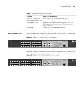
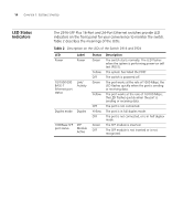
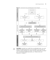
14 CHAPTER 1: GETTING STARTED LED Status Indicators The 2916-SFP Plus 16-Port and 24-Port Ethernet switches provide LED indicators on the front panel for your convenience to monitor the switch. Table 2 describes the meanings of the LEDs. Table 2 Description on the LEDs of the Switch 2916 and 2924 LED Power Label Power 10/100/1000 BASE-T Ethernet port status Link/ Activity Duplex mode Duplex 1000Base SFP SFP port status Module Active Status Green Yellow OFF Green Yellow OFF Yellow OFF Green OFF Description The switch starts normally. The LED flashes when the system is performing power-on self test (POST). The system has failed the POST. The switch is powered off. The port works at the rate of 1000 Mbps; the LED flashes quickly when the port is sending or receiving data. The port works at the rate of 10/100 Mbps; the LED flashes quickly when the port is sending or receiving data. The port is not connected. The port is in full duplex mode. The port is not connected, or is in half duplex mode. The SFP module is inserted. The SFP module is not inserted or is not recognized.
-
 1
1 -
2
-
3
-
4
-
5
-
6
-
7
-
8
-
 9
9 -
 10
10 -
 11
11 -
 12
12 -
 13
13 -
 14
14 -
 15
15 -
 16
16 -
 17
17 -
 18
18 -
 19
19 -
20
-
21
-
22
-
23
-
24
-
25
-
26
-
27
-
28
-
29
-
30
-
31
-
32
-
33
-
34
-
35
-
36
-
37
-
38
-
39
-
40
-
41
-
42
-
43
-
44
-
45
-
46
-
47
-
48
-
49
-
50
-
51
-
52
-
53
-
54
-
55
-
56
-
57
-
58
-
59
-
60
-
61
-
62
-
63
-
64
-
65
-
66
-
67
-
68
-
69
-
70
-
71
-
72
-
73
-
74
-
75
-
76
-
77
-
78
-
79
-
80
-
81
-
82
-
83
-
84
-
85
-
86
-
87
-
88
-
89
-
90
-
91
-
92
-
93
-
94
-
95
-
96
-
97
-
98
-
99
-
100
-
101
-
102
-
103
-
104
-
105
-
106
-
107
-
108
-
109
-
110
-
111
-
112
-
113
-
114
-
115
-
116
-
117
-
118
-
119
-
120
-
121
-
122
-
123
-
124
-
125
-
126
-
127
-
128
-
129
-
130
-
131
-
132
-
133
-
134
-
135
-
136
-
137
-
138
-
139
-
140
-
141
-
142
-
143
-
144
-
145
-
146
-
147
-
148
-
149
-
150
-
151
-
152
-
153
-
154
-
155
-
156
-
157
-
158
-
159
-
160
-
161
-
162
-
163
-
164
-
165
-
166
-
167
-
168
-
169
-
170
-
171
-
172
-
173
-
174
-
175
-
176
-
177
-
178
-
179
-
180
-
181
-
182
-
183
-
184
-
185
-
186
-
187
-
188
-
189
-
190
-
191
-
192
-
193
-
194
-
195
-
196
-
197
-
198
-
199
-
200
-
201
-
202
-
203
-
204
-
205
-
206
-
207
-
208
-
209
-
210
-
211
-
212
-
213
-
214
-
215
-
216
 |
 |