3Com 3CR17562-91 Getting Started Guide
3Com 3CR17562-91 - Switch 4500 Manual
 |
UPC - 662705496245
View all 3Com 3CR17562-91 manuals
Add to My Manuals
Save this manual to your list of manuals |
3Com 3CR17562-91 manual content summary:
- 3Com 3CR17562-91 | Getting Started Guide - Page 1
3Com® Switch 4500 Family Getting Started Guide Switch 4500 26-Port Switch 4500 50-Port Switch 4500 PWR 26-Port Switch 4500 PWR 50-Port www.3Com.com Part No. 10012034, Rev. AC Published: March 2008 - 3Com 3CR17562-91 | Getting Started Guide - Page 2
warranties, terms or conditions of merchantability, satisfactory quality, and fitness for a particular purpose. 3Com may make improvements or changes in the product this User Guide. Unless otherwise indicated, 3Com registered trademarks are , licensed exclusively through X/Open Company, Ltd. IEEE and - 3Com 3CR17562-91 | Getting Started Guide - Page 3
Redundant Power Supply to your Switch 4500 PWR 22 The Power-up Sequence 28 SFP Operation 30 Packing and Shipping the Switch 4500 31 3 MANAGING YOUR SWITCH Methods of Managing a Switch 34 Setting Up Your Switch 35 Viewing Automatically Configured IP Information 38 Manually Configuring IP Information - 3Com 3CR17562-91 | Getting Started Guide - Page 4
Cable 59 Ethernet Port RJ-45 Pin Assignments 60 B OBTAINING SUPPORT FOR YOUR PRODUCT Register Your Product 61 Purchase Value-Added Services 61 Troubleshoot Online 62 Access Software Downloads 62 Telephone Technical Support and Repair 62 Contact Us 62 C 3COM NETWORK MANAGEMENT 3Com Network Supervisor - 3Com 3CR17562-91 | Getting Started Guide - Page 5
Informazioni di Sicurezza 74 Wa¿ne informacje o zabezpieczeniach 75 Regulatory Notices 77 E TECHNICAL SPECIFICATIONS Switch 4500 (26 Port) 79 Switch 4500 (50 Port) 80 Switch 4500 PWR (26 Port) 81 Switch 4500 PWR (50 Port) 82 RPS 83 Earthing Lead 83 F CREATING A STACK How To Interconnect Units 85 - 3Com 3CR17562-91 | Getting Started Guide - Page 6
- 3Com 3CR17562-91 | Getting Started Guide - Page 7
to install and use the following switches in their default state: ■ Switch 4500 26-Port (3CR17561-91) ■ Switch 4500 50-Port (3CR17562-91) ■ Switch 4500 PWR 26-Port (3CR17571-91) ■ Switch 4500 PWR 50-Port (3CR17572-91) All procedures described in this guide apply to all models except where stated - 3Com 3CR17562-91 | Getting Started Guide - Page 8
guide, each Switch documentation set includes the following: ■ Switch 4500 Configuration Guide This guide contains information on the features supported by your Switch and known problems. The Release Notes are supplied in hard copy with your Switch. Your suggestions are very important to us. They - 3Com 3CR17562-91 | Getting Started Guide - Page 9
appropriate) Example: Part Number 10015034 Rev. AB Switch 4500 Family Getting Started Guide Page 21 We can only respond to comments and questions about 3Com product documentation at this e-mail address. Please direct all questions related to technical support or sales in the first instance to your - 3Com 3CR17562-91 | Getting Started Guide - Page 10
10 ABOUT THIS GUIDE - 3Com 3CR17562-91 | Getting Started Guide - Page 11
chapter contains introductory information about the Switch 4500 and how it can be used in your network. It covers summaries of hardware and software features and also the following topics: ■ About the Switch 4500 ■ Switch 4500 - Front View Detail ■ Switch 4500 - Rear View Detail ■ Default Settings - 3Com 3CR17562-91 | Getting Started Guide - Page 12
-T\100BASE-TX Ports 10BASE-T\100BASE-TX PoE Ports 10BASE-T\1000BASE-TX\1000BASE-T Ports 1000BASE-X SFP Ports 1000BASE-T SFP Transceiver RJ-45 Console Port -48V DC RPS Input Switch 4500 Family Switch 4500 26 Port Switch 4500 50 Port Switch 4500 PWR 26 Port Switch 4500 PWR 50 Port 24 2* 2* 1 48 - 3Com 3CR17562-91 | Getting Started Guide - Page 13
Ethernet Ports Supports fiber Gigabit Ethernet short-wave (SX), long-wave (LX), long-haul (LH70) and copper (T) transceivers in any combination. RPS Supplemental PoE Power Connects to -48v DC supply (3CR17571-91 and 3CR17572-91 only) Mounting 19-inch rack or stand-alone mounting Switch 4500 - 3Com 3CR17562-91 | Getting Started Guide - Page 14
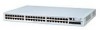
LEDs 10/100BASE-TX Ports Console Port Unit LED PWR LED 3CR17562-91 SuperStack 3 Switch 4500 50-Port 49 50 51/49 52/50 PWR RPS RPS LED 1000BASE-X SFP Ports (Two pairs of Combo Ports fitted with two1000BASE-T SFP transceivers in last two ports) Figure 3 Switch 4500 26-Port PWR - front view - 3Com 3CR17562-91 | Getting Started Guide - Page 15
the Switch 4500 50 Port and PWR 50 Port are: ■ 49 and 51 ■ 50 and 52 By default, the ports are enabled as follows for the 26-Port switches: ■ Port 25 = active; Port 27 = inactive ■ Port 26 = active; Port 28 = inactive By default, the ports are enabled as follows for the 50-Port switches: ■ Port 49 - 3Com 3CR17562-91 | Getting Started Guide - Page 16
16 CHAPTER 1: INTRODUCING THE SWITCH 4500 FAMILY will need to connect an RJ-45 to DB9 converter cable to a standard null modem cable in order to connect a terminal. - 3Com 3CR17562-91 | Getting Started Guide - Page 17
. Yellow flashing One or more ports have failed POST. Red The Switch has failed its Power On Self Test. Off The Switch is not receiving power or there is a fault with the Power Supply Unit. Mode LED (3CR17571-91 and 3CR17572-91 only) Speed Green 10/100 Port Speed and Activity, 1000 SFP - 3Com 3CR17562-91 | Getting Started Guide - Page 18
transmitted/received on the port. Yellow flashing Port failed POST. Off No link is present. Switch 4500 - Rear View Detail Power Socket Figure 5 Switch 4500 - rear view Open Book Warning Labels ~100-240V; 50/60Hz; 1A Figure 6 Switch 4500 PWR - rear view Power Socket Open Book Warning Labels - 3Com 3CR17562-91 | Getting Started Guide - Page 19
Automatic IP Configuration Port Status Port Speed Duplex Mode Power over Ethernet Flow Control Broadcast Storm Control Virtual LANs (VLANs) Management VLAN Link Aggregation Control Protocol (LACP) Switch 4500 Enabled Enabled Auto-negotiated Auto-negotiated Enabled (3CR17571-91 and 3CR17572-91 only - 3Com 3CR17562-91 | Getting Started Guide - Page 20
INTRODUCING THE SWITCH 4500 FAMILY Table 6 Feature Switch 4500 IP Multicast Filtering Filtering enabled Rapid Spanning Tree Protocol Enabled Fast Start Enabled on front panel ports RMON Alarm Enabled Traffic Prioritization All ports prioritize NBX VoIP traffic (LAN and IP). All ports set - 3Com 3CR17562-91 | Getting Started Guide - Page 21
up your Switch 4500. These details are intended to be read together with the printed documents that accompany your switch. ■ Switch unit ■ Unit Information Labels ■ Warranty Information ■ RPS Flyer ■ Power Cord ■ Console Cable (RJ-45) ■ RPS -48V DC Connector and backshell (3CR17571-91 and 3CR17572 - 3Com 3CR17562-91 | Getting Started Guide - Page 22
22 CHAPTER 2: INSTALLING THE SWITCH Connecting a Redundant Power Supply to your Switch 4500 PWR The Switch 4500 PWR 26 and 50 port have a -48V DC Redundant Power Supply socket that can be used in addition to the standard AC connection of the switch. If you intend to use this DC connection, please - 3Com 3CR17562-91 | Getting Started Guide - Page 23
" on page 79. The Switch 4500 PWR units can be powered in three different ways: ■ AC Mains only - does not offer any power redundancy. If the AC mains supply or the AC power supply fail, the Switch will power off. ■ AC Mains and -48V DC (primary supply) - the internal AC supply acts as the backup in - 3Com 3CR17562-91 | Getting Started Guide - Page 24
available to the Switch may be less than when powered from the RPS. Some PoE ports may be dropped as they are unable to obtain the power they require. The unit remains powered by the RPS. The unit is powered by the RPS. PoE ports can be added. Specifying the 3Com's redundant power solution allows - 3Com 3CR17562-91 | Getting Started Guide - Page 25
RPS and that the negative terminal on the Switch is connected to the negative (circuit breaker) terminal of the RPS. Figure 7 shows how to connect the power supply to the RPS socket in the back of the Switch. Use the cable tie supplied with your Switch to support the cable at the rear of the RPS - 3Com 3CR17562-91 | Getting Started Guide - Page 26
. The earthing cable is only required if the Switch is powered by the RPS only. The recommended cable length should not exceed 3 metres (9.84 feet). RPS LED The RPS status LED on the front of the Switch 4500 PWR indicates the status of the RPS and AC supplies as shown in Table 13. Table 13 - 3Com 3CR17562-91 | Getting Started Guide - Page 27
power supply or uninterruptible power supply, increasing its uptime. The Switch supports resistor detection according to IEEE 802.3af and pre-standard detection methods. The Switch 4500 supports 3Com 802.3af equipment. For the latest list of supported devices, refer to the product page on the 3Com - 3Com 3CR17562-91 | Getting Started Guide - Page 28
Problems Indicated by LEDs" on page 52 for a list of suggested solutions. CAUTION: The Switch has no ON/OFF switch; the only method of connecting or disconnecting mains power is by connecting or disconnecting the power cord. WARNING: The Switch 4500 PWR supports Power over Ethernet on 10/100 ports - 3Com 3CR17562-91 | Getting Started Guide - Page 29
The Power-up Sequence 29 Choosing the Correct Cables for the 1000BASE-X SFP Ports The 1000BASE-SX SFP transceiver supports a direct connection to a multi-mode fiber-optic cable. The 1000BASE-LX SFP transceiver supports a direct connection to single-mode and multi-mode fiber-optic cables. The - 3Com 3CR17562-91 | Getting Started Guide - Page 30
with RJ-45 connectors and supports segment lengths of up to 100 m (328 ft). If the SFP transceiver is faulty, it will not operate within the Switch. See "Solving Hardware Problems" on page 53. 3Com recommends that you only use Gigabit Ethernet SFPs supplied by 3Com. If the SFP transceiver is - 3Com 3CR17562-91 | Getting Started Guide - Page 31
Switch 4500 31 3 Gently slide the transceiver into the SFP port until it clicks. If the transceiver does not click into place, remove it, turn it over and re-insert. 4 Remove the plastic protective cover if fitted. Figure 8 Inserting an SFP Transceiver Product label Suitable port on host Switch - 3Com 3CR17562-91 | Getting Started Guide - Page 32
32 CHAPTER 2: INSTALLING THE SWITCH Cable Packaging Back Panel Side of Unit Polystyrene Supports 3Com Switch Unit Front Panel Side of Unit - 3Com 3CR17562-91 | Getting Started Guide - Page 33
Line Interface Management ■ Setting Up Command Line Interface Management using SSH ■ Setting Up Web Interface Management ■ Setting Up SNMP Management ■ Default Users and Passwords n For information on the lost password procedure, refer to the Configuration Guide that is supplied with your switch. - 3Com 3CR17562-91 | Getting Started Guide - Page 34
view is [4500]. Command Line Interface The Switch 4500 supports Secure Shell version 2.0 (SSHv2.0), allowing secure Management using SSH access to the switch's Command Line Interface. If you use SSH to administer your switch and the network traffic is intercepted, no passwords or configuration - 3Com 3CR17562-91 | Getting Started Guide - Page 35
when it is in its default state. The whole setup process is summarized in Figure 14. Detailed procedural steps are contained in the sections that follow. In brief, you need to: ■ Configure IP information manually for your Switch or view the automatically configured IP information ■ Prepare for your - 3Com 3CR17562-91 | Getting Started Guide - Page 36
on default users and changing default passwords, see "Default Users and Passwords" on page 47. IP Configuration You can use one of the following methods to allocate IP information to your switch (essential if you wish to manage your Switch across the network). Configuring IP Manually When - 3Com 3CR17562-91 | Getting Started Guide - Page 37
the risk of the IP address changing. To manually enter IP information for your Switch, work through the "Viewing Automatically Configured IP Information" section on page 38. Automatically Configuring the IP Address using DHCP By default the switch attempts to obtain an IP address from a DHCP server - 3Com 3CR17562-91 | Getting Started Guide - Page 38
to manage the switch. You can discover the IP information by: ■ Connecting a workstation to the switch's console port using a console cable. You can then manually enter the IP information using the command line interface (CLI). ■ Using Network Director or 3Com Network Supervisor. These applications - 3Com 3CR17562-91 | Getting Started Guide - Page 39
running 3Com Network Supervisor or 3Com Network Director must be on the same subnet as the switch because auto-IP addresses are not routable. Manually Configuring IP Information You can manually configure the switch IP information by: ■ Connecting a workstation to the switch's console port using - 3Com 3CR17562-91 | Getting Started Guide - Page 40
the switch using the console port directly. ■ Documentation supplied with the terminal emulation software. ■ The console cable (RJ-45) supplied with your switch. You can find pin-out diagrams for the cable in "Pin-outs" on page 57. ■ IP information, including: ■ IP address ■ subnet mask ■ default - 3Com 3CR17562-91 | Getting Started Guide - Page 41
Manually Configuring IP Information 41 3 Power up the switch. The Power on Self Test (POST) runs automatically. The Switch 4500 takes approximately one minute to boot. Setting Up the Switch with IP Information To manually set up the switch with IP information using the command line interface - 3Com 3CR17562-91 | Getting Started Guide - Page 42
IP address of the default gateway) 7 From the User View, type save to save the switch's configuration (this information is not saved automatically when the switch is powered Port You can manage your switch, including changing IP address information, by making a connection to a front panel port. - 3Com 3CR17562-91 | Getting Started Guide - Page 43
interface or the command line interface (CLI) using telnet. Using the Web Interface 1 Power-up the switch. This takes approximately one minute. 2 Open a suitable Web browser and enter the IP address of your switch in the Address field. If there is no response, wait for one minute then re-enter the - 3Com 3CR17562-91 | Getting Started Guide - Page 44
switch's IP address) c Click OK. 2 Press Enter to open a login prompt. If the login prompt does not begin immediately, press Return a few times until it starts. 3 At the login prompt, enter admin as your user name and press Return at the password prompt. If you have logged on correctly, - 3Com 3CR17562-91 | Getting Started Guide - Page 45
telnet xxx.xxx.xxx.xxx (where xxx.xxx.xxx.xxx is the IP address of the switch) If opening a Telnet session using third party software you will need to enter the IP address in the format suitable for that software. 5 At the login and password prompts, enter admin as your user name and press Return at - 3Com 3CR17562-91 | Getting Started Guide - Page 46
.xxx.xxx.xxx (where xxx.xxx.xxx.xxx is the IP address of the switch) If you get an error message, check that your IP information was entered correctly and the switch is powered up. 3 Open your web browser and enter the IP address of the switch that you wish to manage in the URL locator, for example - 3Com 3CR17562-91 | Getting Started Guide - Page 47
section of the "SuperStack 4 Switch Command Reference Guide" for more information. These switches support SNMP V1, V2, and V3. SNMP V3 is on as default. All commands are in snmp menu in System View. Default Users and Passwords If you intend to manage the switch using the web interface or the - 3Com 3CR17562-91 | Getting Started Guide - Page 48
the following from system view: [4500]local-user admin [4500-luser-admin]password simple xxxxxxxx (where xxxxxxxx is your chosen password). Save the configuration in the User View. For information on the lost password procedure refer to the Configuration Guide that is supplied with your switch. - 3Com 3CR17562-91 | Getting Started Guide - Page 49
49 - 3Com 3CR17562-91 | Getting Started Guide - Page 50
50 CHAPTER 3: MANAGING YOUR SWITCH - 3Com 3CR17562-91 | Getting Started Guide - Page 51
LEDs ■ Solving Hardware Problems ■ Solving Communication Problems ■ Solving Stack Formation Problems If you experience a problem that is not listed here, it may be included in the Support section of the Switch 4500 Command Reference Guide available on 3Com's Web site at www.3com.com. For Technical - 3Com 3CR17562-91 | Getting Started Guide - Page 52
the LEDs on the Switch indicate a problem, refer to the list of suggested solutions below. The PWR LED does not light Check that the power cable is firmly connected to the Switch and to the supply outlet. If the connection is secure and there is still no power, you may have a faulty power cord or an - 3Com 3CR17562-91 | Getting Started Guide - Page 53
or the Web interface, return the unit to 3Com. Unit fails, no SNMP fan failure message is received 1 Power cycle the unit. To do this, remove and reconnect the AC mains supply. If the unit has no AC mains supply, remove and reconnect the DC RPS supply. 2 Check the command line interface (display - 3Com 3CR17562-91 | Getting Started Guide - Page 54
has identified that the SFP does not meet the minimum requirements for the Switch and has disabled the port. To correct this problem, completely remove the SFP and replace it with a 3Com approved SFP. See "Approved SFP Transceivers" on page 30. Error message indicating that the SFP transceiver - 3Com 3CR17562-91 | Getting Started Guide - Page 55
.255.255.0. These suggested IP addresses are part of a group of IP addresses that have been set aside specially for use 'in house' only. A device is connected to a Switch 4500 PWR but power is not being supplied If power is not being supplied to a device connected to a Switch 4500 PWR, you should do - 3Com 3CR17562-91 | Getting Started Guide - Page 56
4: PROBLEM SOLVING The 4500 PWR will only supply power through the front panel port to 802.3af compliant devices. ■ Check that power budget for the Switch has not been exceeded. If the power budget has been exceeded, then by default, the powered device connected to the Power over Ethernet port with - 3Com 3CR17562-91 | Getting Started Guide - Page 57
If you are having problems with correctly forming a stack, first ensure that Spanning Tree is enabled. If it is enabled, do the following: 1 Power off all units in the stack. 2 Check all the cable connections in the stack. 3 Check the ports have been enabled as stack ports. 4 Power on all units in - 3Com 3CR17562-91 | Getting Started Guide - Page 58
58 CHAPTER 4: PROBLEM SOLVING - 3Com 3CR17562-91 | Getting Started Guide - Page 59
20 DTR 5 CTS required for handshake 6 DSR 8 DCD RJ-45 to 9-pin Switch 4500 Cable connector: RJ-45 female Screen Shell DTR 4 TxD 3 RxD 2 CTS 8 Ground 5 DSR 6 RTS 7 DCD 1 PC-AT Serial Port Cable connector: 9-pin female Shell Screen only required if screen 1 DCD Required - 3Com 3CR17562-91 | Getting Started Guide - Page 60
60 APPENDIX A: PIN-OUTS Ethernet Port RJ-45 Pin Assignments Switch 4500 Cable connector: RJ-45 female Screen Shell TxD 3 RxD 2 RTS 7 CTS 8 DSR 6 Ground 5 DCD 1 DTR 4 RS-232 Modem Port Cable connector: 25-pin male 1 Screen 2 TxD 3 RxD 4 RTS 5 CTS 6 DSR 7 Ground 8 - 3Com 3CR17562-91 | Getting Started Guide - Page 61
Request. If you have trouble registering your product, please contact 3Com Global Services for assistance. Purchase Value-Added Services To enhance response times or extend warranty benefits, contact 3Com or your authorized 3Com reseller. Value-added services like 3Com ExpressSM and GuardianSM can - 3Com 3CR17562-91 | Getting Started Guide - Page 62
. If your product is registered and under warranty, you can obtain an RMA number online at http://eSupport.3com.com/. First time users will need to apply for a user name and password. Contact Us 3Com offers telephone, e-mail and internet access to technical support and repair services. To access - 3Com 3CR17562-91 | Getting Started Guide - Page 63
Contact Us 63 Telephone numbers are correct at the time of publication. Find a current directory of contact information posted on the 3Com web site at http://csoweb4.3com.com/contactus/ Country Telephone Number Country Telephone Number Asia, Pacific Rim Telephone Technical Support and Repair - 3Com 3CR17562-91 | Getting Started Guide - Page 64
B: OBTAINING SUPPORT FOR YOUR PRODUCT Country Telephone Number Country You can also obtain support in this region using the following: Spanish speakers, enter the URL: http://lat.3com.com/lat/support/form.html Portuguese speakers, enter the URL: http://lat.3com.com/br/support/form.html - 3Com 3CR17562-91 | Getting Started Guide - Page 65
address networks of all sizes and complexity, from small and medium businesses through large enterprises. The applications include: ■ 3Com Network Supervisor ■ 3Com Network Director ■ 3Com Network Access Manager ■ 3Com Enterprise Management Suite ■ Integration Kit with HP intelligent defaults and - 3Com 3CR17562-91 | Getting Started Guide - Page 66
3Com device configurations as well as firmware and agent upgrades. 3ND makes it easy to roll out network-wide configuration changes with its intelligent VLAN configuration tools and the powerful . 3Com Network Access Manager leverages the advanced desktop security capabilities of 3Com switches and - 3Com 3CR17562-91 | Getting Started Guide - Page 67
, security switches, the 3Com VCX™ IP Telephony server, and wireless access points: ■ Up to 250 devices ■ Up to 1,000 devices ■ Up to 5,000 devices ■ An unlimited number of devices To find out more about 3Com Enterprise Management Suite, go to: www.3com.com/ems Integration Kit with HP OpenView - 3Com 3CR17562-91 | Getting Started Guide - Page 68
68 APPENDIX C: 3COM NETWORK MANAGEMENT - 3Com 3CR17562-91 | Getting Started Guide - Page 69
instructions supplied with your RPS. WARNING: When powering any Switch 4500 from an RPS, the unit must be earthed (grounded). This can be achieved by either connecting the power open (off) position when connecting the cable to the RPS. WARNING: You must ensure that the positive terminal on the Switch - 3Com 3CR17562-91 | Getting Started Guide - Page 70
(Redundant Power Supply) ne doit être confiée qu'à un personnel formé et qualifié. AVERTISSEMENT: Ces instructions doivent être lues conjointement avec les instructions d'installation et les consignes de sécurité qui accompagnent le RPS. AVERTISSEMENT: Lorsqu'un commutateur Switch 4500 est aliment - 3Com 3CR17562-91 | Getting Started Guide - Page 71
aux équipements de télécommunication avec les commutateurs réseau PoE (Power-Over-Ethernet) de 3Com. En vue de respecter la spécification IEEE 802.3af ( : Die RPS (Redundant Power Supply, redundante Stromversorgung) darf VORSICHT: Bei der Stromversorgung eines Switch 4500 über eine RPS muss das Ger - 3Com 3CR17562-91 | Getting Started Guide - Page 72
POWER SUPPLY SAFETY INFORMATION VORSICHT: Diese Anleitungen müssen im Zusammenhang mit den Eigenschaften des Gleichstrom-Versorgungseingangs des Switch 4500 des Steckers des 3Com Switch in der geöffneten Stellung (Aus) befindet. VORSICHT: Verwenden Sie mit den 3Com PoE-Netzwerkswitches kein - 3Com 3CR17562-91 | Getting Started Guide - Page 73
características de la entrada de suministro de CC del Switch 4500 del Apéndice C, Especificaciones técnicas. ADVERTENCIA: al posición de abierto (desactivado) al conectar el cable del RPS y el conector al Switch 3Com. ADVERTENCIA: No utilice un sistema de alimentación eléctrica redundante de -48 V - 3Com 3CR17562-91 | Getting Started Guide - Page 74
dell'RPS (Redundant Power Supply) devono essere eseguite esclusivamente da personale qualificato e opportunamente addestrato. AVVERTENZA: queste istruzioni devono essere lette insieme alle istruzioni di sicurezza e installazione fornite con l'RPS. AVVERTENZA: se si accende uno Switch 4500 da un RPS - 3Com 3CR17562-91 | Getting Started Guide - Page 75
należy przeczytać razem z instrukcjami dotyczącymi bezpieczeństwa i instalacji dostarczonymi z systemem zasilania nadmiarowego. OSTRZEŻENIE: Jeśli dowolny przełącznik Switch 4500 jest zasilany z zasilacza RPS, urządzenie musi być uziemione. Można to uzyskać przez podłączenie przewodu zasilającego do - 3Com 3CR17562-91 | Getting Started Guide - Page 76
76 APPENDIX D: REDUNDANT POWER SUPPLY SAFETY INFORMATION jest podłączona do dodatniej (wspólnej) końcówki odpowiedniego przy użyciu ze sprzętem telekomunikacyjnym wraz z przełącznikami sieciowymi firmy 3Com w technologii Power-over-Ethernet (PoE). Aby spełnić wymagania specyfikacji IEEE 802.3af (PoE - 3Com 3CR17562-91 | Getting Started Guide - Page 77
in accordance with the instructions, may cause harmful identify and resolve radio-TV interference problems This booklet is available from the Product Support web page for the Switch 4500 Product Family at http://www.3com.com. Also available at http://support.3com.com/doc/Switch_4500_EU_DOC.pdf - 3Com 3CR17562-91 | Getting Started Guide - Page 78
78 APPENDIX D: REDUNDANT POWER SUPPLY SAFETY INFORMATION - 3Com 3CR17562-91 | Getting Started Guide - Page 79
E TECHNICAL SPECIFICATIONS Switch 4500 (26 Port) Physical Dimensions Environmental Requirements Operating Temperature Storage Temperature Operating Humidity Standards Safety Agency Certifications EMC Emissions Immunity Power Consumption Heat Dissipation Power Supply AC Line Frequency Input - 3Com 3CR17562-91 | Getting Started Guide - Page 80
80 APPENDIX E: TECHNICAL SPECIFICATIONS Switch 4500 (50 Port) Physical Dimensions Environmental Requirements Operating Temperature Storage Temperature Operating Humidity Standards Safety Agency Certifications EMC Emissions Immunity Power Consumption Heat Dissipation Power Supply AC Line Frequency - 3Com 3CR17562-91 | Getting Started Guide - Page 81
Switch 4500 PWR (26 Port) 81 Switch 4500 PWR (26 Port) Physical Dimensions Environmental Requirements Operating Temperature Storage Temperature Operating Humidity Standards Safety Agency Certifications EMC Emissions Immunity Power Consumption Heat Dissipation Power Supply to 3Com schedule 50 - 3Com 3CR17562-91 | Getting Started Guide - Page 82
Switch 4500 PWR (50 Port) Physical Dimensions Environmental Requirements Operating Temperature Storage Temperature Operating Humidity Standards Safety Agency Certifications EMC Emissions Immunity Power Consumption Heat Dissipation Power Supply condensing EN60068 to 3Com schedule (Package Supported IP - 3Com 3CR17562-91 | Getting Started Guide - Page 83
Class A, FCC Part 15 Subpart B Class A, ICES-003 Class A, AS/NZS 3548 Class A, VCCI Class A, EN61000-3-2, EN61000-3-3 EN 55024 Must meet DC power supply specifications for each unit (as defined above). The Earthing Lead shall comply with the following safety standards: UL Subject 758, UL 1581 and - 3Com 3CR17562-91 | Getting Started Guide - Page 84
84 APPENDIX E: TECHNICAL SPECIFICATIONS - 3Com 3CR17562-91 | Getting Started Guide - Page 85
by interconnecting a 3Com Switch 4500 with other 3Com Switch 4500s. This section assumes you have either set up your units for management as detailed in Chapter 3 "Managing Your Switch"or that you are using a console cable connected to the console port to set up and allocate IP addresses and so on - 3Com 3CR17562-91 | Getting Started Guide - Page 86
Yellow = Half Duplex 10/100BASE-TX 3CR17562-91 SuperStack 3 Switch 4500 50-Port 49 50 49 50 PWR RPS 25 26 25 26 3CR17561-91 SuperStack 3 Switch 4500 26-Port 1000BASE-X 10/100/1000BASE-T 25 26 25 26 3CR17561-91 SuperStack 3 Switch 4500 26-Port 1000BASE-X 10/100/1000BASE-T 25 26 - 3Com 3CR17562-91 | Getting Started Guide - Page 87
the Switch with the lowest MAC address assumes the ID in question and the other unit will automatically renumber. 3Com recommends that you manually assign continue to work normally. Renumbering only occurs when the stack is next power cycled if the units are configured to auto-number. The unit LEDs - 3Com 3CR17562-91 | Getting Started Guide - Page 88
88 Appendix F: CREATING A STACK
-
 1
1 -
 2
2 -
 3
3 -
 4
4 -
 5
5 -
 6
6 -
 7
7 -
8
-
9
-
10
-
11
-
12
-
13
-
14
-
15
-
16
-
17
-
18
-
19
-
20
-
21
-
22
-
23
-
24
-
25
-
26
-
27
-
28
-
29
-
30
-
31
-
32
-
33
-
34
-
35
-
36
-
37
-
38
-
39
-
40
-
41
-
42
-
43
-
44
-
45
-
46
-
47
-
48
-
49
-
50
-
51
-
52
-
53
-
54
-
55
-
56
-
57
-
58
-
59
-
60
-
61
-
62
-
63
-
64
-
65
-
66
-
67
-
68
-
69
-
70
-
71
-
72
-
73
-
74
-
75
-
76
-
77
-
78
-
79
-
80
-
81
-
82
-
83
-
84
-
85
-
86
-
87
-
88
 |
 |

3Com
®
Switch 4500 Family
Getting Started Guide
Switch 4500 26-Port
Switch 4500 50-Port
Switch 4500 PWR 26-Port
Switch 4500 PWR 50-Port
www.3Com.com
Part No. 10012034, Rev. AC
Published: March 2008