3Com 3CRWEASYA73 Quick Start Guide
3Com 3CRWEASYA73 - 11a 54 Mbps Wireless LAN Outdoor Manual
 |
UPC - 662705506647
View all 3Com 3CRWEASYA73 manuals
Add to My Manuals
Save this manual to your list of manuals |
3Com 3CRWEASYA73 manual content summary:
- 3Com 3CRWEASYA73 | Quick Start Guide - Page 1
supplied by Power Over Ethernet (PoE) using a: • 3Com propriety PoE Injector (output: 48V 60W) About This Guide This Quick Start Guide describes the basic installation of the bridge. It covers the following topics: • 3Com WL-575 Outdoor Building-to-Building Bridge and Access Point • Observing Safety - 3Com 3CRWEASYA73 | Quick Start Guide - Page 2
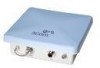
3Com WL-575 Outdoor Building-to-Building Bridge and Access Point Features Bottom View Top View Console Port Connector Grounding Point LEDs Water Tight Test Point (DO NOT REMOVE) PoE Connector Integrated Antenna N-Type External Antenna Connector (2.4 GHz) N-Type External Antenna Connector (5 - 3Com 3CRWEASYA73 | Quick Start Guide - Page 3
Access Point • Mounting bracket and hardware • One Weatherproof Category 5 network cable • One Weatherproof Console to RS232 cable • PoE power injector/ Ethernet connector and AC power cord • One grounding screw, not attached • This Quick Start Guide • One CD-ROM containing the Setup Wizard software - 3Com 3CRWEASYA73 | Quick Start Guide - Page 4
IP address labels are shipped with the bridge. The WL-575 bridge must only be installed outdoors. It is not for indoor use. The PoE injector is for indoor use for outdoor use only. Do not install the bridge indoors. Using the Pole or tube using the mounting bracket: 1 Place the V-shaped part of the - 3Com 3CRWEASYA73 | Quick Start Guide - Page 5
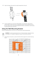
2 Fit the edges of the V-shaped part into the slots in the rectangular plate, and tighten the nuts. Slots 3 Attach the adjustable rectangular plate to the bridge with the supplied screws. 5 - 3Com 3CRWEASYA73 | Quick Start Guide - Page 6
the wireless bridge tilt angle may need to be adjusted during the antenna alignment process. Be sure to take account of the antenna polarization direction; all antennas in a link must be mounted with the same polarization. Using the Wall-Mounting Bracket Perform the following steps to mount the unit - 3Com 3CRWEASYA73 | Quick Start Guide - Page 7
a 5.0 GHz antenna, and access point operation a 2.4 GHz antenna. WL-575 units acting as managed APs also require an external antenna for 2.4 GHz operation. Perform these steps: 1 Mount the external antenna to the same supporting structure as the bridge, within 3 m (10 ft) distance, using the bracket - 3Com 3CRWEASYA73 | Quick Start Guide - Page 8
sure to use the management interface to configure the bridge for correct antenna operation. 2.4 GHz N-type Connector 5 GHz 2.4 GHz N-type Connector N-type Connector 5 GHz External High-gain Panel Antenna RF Coaxial Cable 2.4 GHz External Omnidirectional Antenna 5 Connecting Cables 1 Attach - 3Com 3CRWEASYA73 | Quick Start Guide - Page 9
not support Power over Ethernet (PoE) based on the IEEE 802.3af standard. Do not try to power the unit power injector. 2 Connect a straight-through unshielded twisted-pair (UTP) cable from a local LAN switch to the RJ-45 port labeled "Input" on the power injector. Use Category 5e or better UTP cable - 3Com 3CRWEASYA73 | Quick Start Guide - Page 10
Hub/ Switch Input Output AC power Power LED indicator "Output" to Bridge 3 Insert the power cable plug directly into the standard AC socket on the power injector. 4 Plug the other end of the power cable into a grounded, 3-pin socket, AC power source. NOTE: For International use, you may need to - 3Com 3CRWEASYA73 | Quick Start Guide - Page 11
The bridge's 11a and 11b/g LEDs operate in two display modes, which are configurable through the software. The default AP mode indicates data traffic rates. The RSSI mode indicates the received signal power and is for use when aligning antennas in a bridge link. When the bridge is connected to - 3Com 3CRWEASYA73 | Quick Start Guide - Page 12
aligned to ensure optimum performance. This alignment process is particularly important for long-range point-to-point links. In a point-to-multipoint configuration the root bridge uses an omnidirectional or sector antenna, which does not require alignment, but bridge nodes still need to be correctly - 3Com 3CRWEASYA73 | Quick Start Guide - Page 13
the antenna slowly up and down while checking the LEDs. 4 Find the point where the signal is strongest and secure the vertical adjustment in that position. Troubleshooting Refer to the 3Com WL-575 Outdoor Building-to-Building Bridge and Access Point User's Guide or the 3Com website (www.3Com.com - 3Com 3CRWEASYA73 | Quick Start Guide - Page 14
Information The 3Com Outdoor 11a Building to Building Bridge and 11bg Access Point, Model WL-575 (3CRWEASYA73) must be installed and used in strict accordance with the manufacturer's instructions as described in the user documentation that comes with the product. This product contains encryption - 3Com 3CRWEASYA73 | Quick Start Guide - Page 15
and 11bg Access Point, Model WL-575 (3CRWEASYA73), or the substitution or attachment of connecting cables and equipment other than specified by 3Com. The correction of interference caused by such unauthorized modification, substitution or attachment will be the responsibility of the user. Changes or - 3Com 3CRWEASYA73 | Quick Start Guide - Page 16
, and (2) this device must accept any interference received, including interference that may cause undesired operation. 3Com Outdoor 11a Building to Building Bridge and 11bg Access Point Model WL-575 Industry Canada - RF Compliance This device complies with RSS 210 of Industry Canada. Operation is - 3Com 3CRWEASYA73 | Quick Start Guide - Page 17
GB IS LI NO CH BG RO TR Intended use: IEEE 802.11b/g/a radio LAN device NOTE: To ensure product operation is in compliance with local regulations, select the country in which the product is installed. Refer to installation instructions. Česky [Czech] Dansk [Danish] Deutsch [German] Eesti [Estonian - 3Com 3CRWEASYA73 | Quick Start Guide - Page 18
of Conformity can be downloaded from the Product Support web page for the 3Com Outdoor 11a Building to Building Bridge and 11bg Access Point, Model WL-575 (3CRWEASYA73) at http://www.3com.com. Also available at http://support.3com.com/doc/WL-575_EU_DOC.pdf EU - Restrictions for Use in the 2.4GHz - 3Com 3CRWEASYA73 | Quick Start Guide - Page 19
when using the bands 5150-5350MHz (Channels 36, 40, 44, 48, 52, 56, 50, 64). • In Italy the end-user must apply support staff responsible for the wireless network to ensure the Bridge/ Access Point device(s) are properly configured service in relation to human life security is not available. 19 - 3Com 3CRWEASYA73 | Quick Start Guide - Page 20
• Output: 48 VDC, 1.2 A • Power consumption: 13.2 watts Unit Power Supply • PoE input: 48 VDC, 0.6 A maximum • Power consumption: 28 watts maximum Physical Size • 3Com Corporation. All rights reserved. 3Com and the 3Com logo are registered trademarks of 3Com Corporation. All other company and product
-
 1
1 -
 2
2 -
 3
3 -
 4
4 -
 5
5 -
 6
6 -
 7
7 -
8
-
9
-
10
-
11
-
12
-
13
-
14
-
15
-
16
-
17
-
18
-
19
-
20
 |
 |

Quick Start Guide
3Com Wireless
802.11a Outdoor Building-to-Building
Bridge and Access Point
3CRWEASYA73 / WL-575
The 3Com WL-575 802.11a Outdoor Building-to-Building Bridge and Access Point provides IEEE
802.11a or 802.11b/g wireless access to the network. The bridge offers a fast, reliable, and cost-
effective solution for connectivity between remote Ethernet wired LANs or to provide Internet access
to an isolated site.
Power is supplied by Power Over Ethernet (PoE) using a:
•
3Com propriety PoE Injector (output: 48V 60W)
About This Guide
This Quick Start Guide describes the basic installation of the bridge. It covers the following topics:
•
3Com WL-575 Outdoor Building-to-Building Bridge and Access Point
•
Observing Safety Precautions
•
Step 1: Unpacking the Bridge
•
Step 2: Preparing for Installation
•
Step 3: Mounting the Bridge
•
Step 4: Connecting External Antennas
•
Step 5: Connecting Cables
•
Step 6: Connecting the Power (PoE Injector)
•
Step 7: Checking the LED Indicators
•
Step 8: Aligning Antennas
•
Troubleshooting