3Com 4226T Getting Started Guide
3Com 4226T - SuperStack 3 Switch Manual
 |
View all 3Com 4226T manuals
Add to My Manuals
Save this manual to your list of manuals |
3Com 4226T manual content summary:
- 3Com 4226T | Getting Started Guide - Page 1
SuperStack® 3 Switch 4200 Series Getting Started Guide 3C17300 3C17302 3C17304 http://www.3com.com/ Part No. DUA1730-0AAA02 Published October 2002 - 3Com 4226T | Getting Started Guide - Page 2
to you in conjunction with, this User Guide. Unless otherwise indicated, 3Com registered trademarks are registered in the United States and may or may not be registered in other countries. 3Com, the 3Com logo and SuperStack are all registered trademarks of 3Com Corporation. Novell and NetWare are - 3Com 4226T | Getting Started Guide - Page 3
- Front View Detail 13 10BASE-T/ 100BASE-TX Ports 14 10/100/1000BASE-T Ports 14 GBIC Ports 14 LEDs 15 Switch 4200 Series - Rear View Detail 17 Power Socket 17 Redundant Power System Socket 17 Console Port 17 Default Settings 18 2 INSTALLING THE SWITCH Package Contents 20 Choosing a Suitable Site 20 - 3Com 4226T | Getting Started Guide - Page 4
33 Preparing for Management 34 Manually Configuring IP Information 35 Connecting to a Front Panel Port 35 Connecting to the Console Port 38 Viewing Automatically Configured IP Information 42 Using 3Com Network Supervisor 42 Connecting to the Console Port 42 Methods of Managing a Switch 45 Command - 3Com 4226T | Getting Started Guide - Page 5
67 Modem Cable 68 RJ-45 Pin Assignments 68 1000BASE-T RJ-45 Pin Assignments 69 C TECHNICAL SPECIFICATIONS Switch 4226T (3C17300) 71 Switch 4250T (3C17302) 73 Switch 4228G (3C17304) 74 D TECHNICAL SUPPORT Online Technical Services 75 World Wide Web Site 75 3Com Knowledgebase Web Services 76 3Com FTP - 3Com 4226T | Getting Started Guide - Page 6
INDEX REGULATORY NOTICES - 3Com 4226T | Getting Started Guide - Page 7
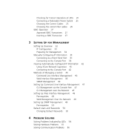
a SuperStack® 3 Switch 4200 in its default state. This guide is intended for use with all Switch 4200 Series models: ■ Switch 4226T (3C17300) - 24 10BASE-T/100BASE-TX ports, 2 10/100/1000BASE-T ports ■ Switch 4250T (3C17302) - 48 10BASE-T/100BASE-TX ports, 2 10/100/1000BASE-T ports ■ Switch 4228G - 3Com 4226T | Getting Started Guide - Page 8
your password, use the following syntax: system password Commands In this example, you must supply a password for . port detail When you see the word "enter" in this guide, you must type something, and then press Return or Enter. Do not press Return or Enter when an instruction - 3Com 4226T | Getting Started Guide - Page 9
be used to optimize your network. It is supplied in PDF format on the CD-ROM that accompanies the Switch. ■ SuperStack 3 Switch Management Quick Reference Guide This guide contains: ■ a list of the software features supported by the Switch. ■ a summary of the web interface and command line interface - 3Com 4226T | Getting Started Guide - Page 10
Accessing Online The CD-ROM supplied with your Switch contains the following online Documentation documentation: ■ SuperStack 3 Switch Implementation Guide (PDF format) ■ SuperStack 3 Switch Management Interface Reference Guide (HTML format) 1 To access the documentation insert the CD-ROM into - 3Com 4226T | Getting Started Guide - Page 11
INTRODUCING THE SUPERSTACK 3 SWITCH 4200 SERIES This chapter contains introductory information about the Switch 4200 Series and how it can be used in your network. It covers summaries of hardware and software features and also the following topics: ■ About the Switch 4200 Series ■ Switch 4200 Series - 3Com 4226T | Getting Started Guide - Page 12
and Fast Ethernet Auto-negotiating 10BASE-T/100BASE-TX ports Ports Gigabit Ethernet Auto-negotiating 10/100/1000BASE-T ports GBIC Auto-negotiating GBIC ports (Switch 4228G only) RPS Support Connects to SuperStack Advanced Redundant Power System (ARPS) (3C16071, 3C16071A or 3C16071B) Mounting - 3Com 4226T | Getting Started Guide - Page 13
/ Self Test 1 25 / Up 26 / Down 2 3 Alert 4 Unit Alert LED 10/100/1000BASE-T ports 3C17300 Superstack 3 Switch 4226T Figure 2 Switch 4250T (3C17302) - front view 10BASE-T / 100BASE-TX RJ-45 Ports Unit LEDs Power / Self Test LED 1 25 2 26 3 27 4 28 5 29 6 30 7 31 8 32 9 33 10 34 11 35 - 3Com 4226T | Getting Started Guide - Page 14
length is 100 m (328 ft) over Category 5 cable. The 10/100/1000BASE-T ports will auto-negotiate to the appropriate speed. GBIC Ports This section applies to the SuperStack 3 Switch 4228G only. The two GBIC ports support Category 5 twisted pair cable and fiber Gigabit Ethernet short-wave (SX), long - 3Com 4226T | Getting Started Guide - Page 15
flow control setting can be manually configured. 1000BaseT GBIC's These ports will auto-negotiate to SuperStack 3 Switch Management Interface Reference Guide" on the CD-ROM that is supplied with the Switch. Table 4 LED behavior LED Color Indicates Port Status LEDs 10BASE-T/100BASE-TX ports - 3Com 4226T | Getting Started Guide - Page 16
Test LED Green The Switch is powered-up and operating normally. Green flashing The Switch is either downloading software or is initializing (which includes running a Power On Self Test). Yellow The Switch has failed its Power On Self Test. Refer to Chapter 4 Solving Problems Indicated by LEDs - 3Com 4226T | Getting Started Guide - Page 17
a Switch 4200 to a SuperStack Advanced Redundant Power System (RPS). See "Connecting a Redundant Power System" on page 25. Console Port The console port allows you to connect a terminal and perform remote or local out-of-band management. The console port uses a standard null modem cable and - 3Com 4226T | Getting Started Guide - Page 18
18 CHAPTER 1: INTRODUCING THE SUPERSTACK 3 SWITCH 4200 SERIES Default Settings Table 5 shows the default settings for the Switch 4200 Series: Table 5 Default Settings Feature Switch 4200 Series Automatic IP Configuration Enabled Port Status Enabled Port Speed All ports are auto-negotiated - 3Com 4226T | Getting Started Guide - Page 19
Other ■ The Power-up Sequence ■ GBIC Operation WARNING: Safety Information. Before installing or removing any components from the Switch 4200 Series or in Appendix A of this guide. AVERTISSEMENT: Consignes de sécurité. Avant d'installer ou d'enlever tout composant du Switch 4200 ou d'entamer une - 3Com 4226T | Getting Started Guide - Page 20
as radios, transmitters and broadband amplifiers. ■ power lines and fluorescent lighting fixtures ■ The Switch is accessible and cables can be connected easily. ■ Water or moisture cannot enter the case of the Switch. ■ Air-flow is not restricted around the Switch or through the vents in the side of - 3Com 4226T | Getting Started Guide - Page 21
will fit in most standard 19-inch racks. CAUTION: Disconnect all cables from the Switch before continuing. Remove all self adhesive pads from the underside of the Switch if they have been fitted. To rack-mount your Switch: 1 Place the Switch the right way up on a hard flat surface, with the front - 3Com 4226T | Getting Started Guide - Page 22
. 6 Connect network cabling. 7 Finally place a unit information label on the unit in an easily accessible position. The unit information label shows the following: ■ The 3Com product name of the Switch ■ The 3Com 3C number of the Switch ■ The unique MAC address (Ethernet address) of the Switch ■ The - 3Com 4226T | Getting Started Guide - Page 23
Power/ Self Test 1 25 / Up 26 / Down 2 3 Alert 4 Unit 3C17300 Superstack 3 Switch 4226T The unit LEDs will display the unit number in the stack, from 1 at the bottom to 4 at the top. 3Com recommends that when you add a new unit to a stack, you should first initialize it to factory default - 3Com 4226T | Getting Started Guide - Page 24
end of the power cord into your power outlet. The Switch powers-up and runs through its Power On Self Test (POST), which takes approximately 10 seconds. Checking for Correct Operation of LEDs During the Power On Self Test, all ports on the Switch are disabled and the LEDs light in a set sequence - 3Com 4226T | Getting Started Guide - Page 25
not complete. 3Com recommends that you do not use the Switch's management interface until the Unit LED is green. If there is evidence of a problem, see "Solving Problems Indicated by LEDs" on page 54. Connecting a Redundant Power System You can connect a SuperStack Advanced Redundant Power System - 3Com 4226T | Getting Started Guide - Page 26
use multimode or single-mode fiber optic cables. For detailed information on fiber cable specifications, refer to the SuperStack 3 Implementation Guide that accompanies your Switch. If you wish to connect a 1000BASE-SX MT-RJ port to a fiber port with a different type of connector, for example - 3Com 4226T | Getting Started Guide - Page 27
. This section applies to the SuperStack 3 Switch 4228G only. GBIC transceivers are hot-insertable and hot-swappable. You can remove them from and insert them into any GBIC port without having to power down the Switch. Approved GBIC Transceivers The 3Com approved GBIC transceivers are: ■ 1000BASE - 3Com 4226T | Getting Started Guide - Page 28
faulty, it will not operate within the Switch. See "Solving Hardware Problems" on page 55. Do not use non-3Com GBICs. If the GBIC transceiver is invalid it will not be recognised by the Switch. Use the following sequence of steps to activate the GBIC ports. 1 To insert one of the transceivers into - 3Com 4226T | Getting Started Guide - Page 29
Figure 7 Inserting a GBIC Transceiver GBIC Operation 29 erstack 3 Switch 4228G GBIC Ports GBIC Transceiver 3 The transceiver connects to the network using a duplex SC connector. Attach a male duplex SC connector on the network cable into the duplex SC connector on the transceiver. 4 Connect the - 3Com 4226T | Getting Started Guide - Page 30
30 CHAPTER 2: INSTALLING THE SWITCH - 3Com 4226T | Getting Started Guide - Page 31
topics: ■ Setting Up Overview ■ Manually Configuring IP Information ■ Viewing Automatically Configured IP Information ■ Methods of Managing a Switch ■ Setting Up Command Line Interface Management ■ Setting Up Web Interface Management ■ Setting Up SNMP Management ■ Default Users and Passwords - 3Com 4226T | Getting Started Guide - Page 32
to: ■ Configure IP information manually for your Switch or view the automatically configured IP information ■ Prepare for your chosen method of management Figure 8 Initial Switch Setup and Management Flow diagram Power up the Switch. Plug and Play Setup Initial IP Information Setup IP information - 3Com 4226T | Getting Started Guide - Page 33
of the IP address changing. If you wish to manually enter IP information for your Switch, work through the "Manually Configuring IP Information" section on page 35. Automatic IP Configuration By default the Switch tries to configure itself with IP information without requesting user intervention. It - 3Com 4226T | Getting Started Guide - Page 34
of Managing a Switch" on page 45. For detailed information about the specific web interface operations and command line interface commands and problem solving, refer to the "SuperStack 3 Switch Management Interface Reference Guide" on the CD-ROM that is supplied with the Switch or on the 3Com Web - 3Com 4226T | Getting Started Guide - Page 35
manually you can make a connection to a front Panel Port panel port. You must do this whilst the Switch is offline, that is, before you connect the Switch to a network. The procedure described in this section assumes the unit has been powered up in standalone mode and has the default IP address - 3Com 4226T | Getting Started Guide - Page 36
RJ-45 connector at the other end of the cable to one of the front panel ports on the Switch. Do not interconnect the Switch to any other unconfigured Switch. Configuring the Workstation with IP Information You need to change the IP address and subnet mask of the workstation that you have connected - 3Com 4226T | Getting Started Guide - Page 37
Manually Configuring IP Information 37 If there is no response, wait for one minute then re-enter the default IP address. 3 At the login and password prompts, enter admin as your user name and press Return at the password prompt (default user name and password). If you have logged on correctly, a - 3Com 4226T | Getting Started Guide - Page 38
gateway IP address for the Switch. The screen displays a summary of the information entered. The initial set up of your Switch is now complete and the Switch is ready for you to set up your chosen management method. See "Methods of Managing a Switch" on page 45. Connecting to the Console Port To - 3Com 4226T | Getting Started Guide - Page 39
need to have the following so that you can manually set up the Switch with IP information: ■ IP address ■ subnet mask ■ default gateway Connecting the Workstation to the Switch 1 Connect the workstation to the console port using a standard null modem cable as shown in Figure 11. Figure 11 Connecting - 3Com 4226T | Getting Started Guide - Page 40
40 CHAPTER 3: SETTING UP FOR MANAGEMENT 2 Open your terminal emulation software and configure the COM port settings to which you have connected the cable. The settings should be set to match the default settings for the Switch, which are: ■ 19,200 baud ■ 8 data bits ■ no parity ■ 1 stop bit ■ no - 3Com 4226T | Getting Started Guide - Page 41
and the Switch is ready for you to set up your chosen management method. See "Methods of Managing a Switch" on page 45. If you do not intend to use the command line interface via the console port to manage the Switch, you can disconnect the serial cable and close the terminal emulator software. - 3Com 4226T | Getting Started Guide - Page 42
a DHCP or BootP server, the workstation running 3Com Network Supervisor must be on the same subnet as the Switch, because Auto-IP addresses are non-routable. Connecting to the Console Port Alternatively, you can view the automatically configured IP information via the command line interface (CLI - 3Com 4226T | Getting Started Guide - Page 43
the console port of the Switch. b Tighten the retaining screws on the cable to prevent it from being loosened. c Connect the other end of the cable to one of the serial ports (also known as a COM port) on your workstation. 2 Open your terminal emulation software and configure the COM port settings - 3Com 4226T | Getting Started Guide - Page 44
available, it then allocates an IP address in the range of 169.254.x.y (where x is in the range 1 to 254, and y is in the range 0 to 255). 2 The command line interface login sequence begins as soon as the Switch detects a connection to its console port. If the login prompt does not begin immediately - 3Com 4226T | Getting Started Guide - Page 45
the Network IP Address. The initial set up of your Switch is now complete and the Switch is ready for you to set up your chosen management method. See "Methods of Managing a Switch" on page 45. If you do not intend to use the command line interface via the console port to manage the Switch, you can - 3Com 4226T | Getting Started Guide - Page 46
via the console port Figure 16 CLI management over the network Refer to "Setting Up Command Line Interface Management" on page 47. Web Interface Each Switch has an internal set of web pages that allow you to manage Management the Switch using a Web browser remotely over an IP network (see - 3Com 4226T | Getting Started Guide - Page 47
is now ready to continue being managed and/or configured through the CLI via its console port. CLI Management over To manage a Switch using the command line interface over a network the Network using Telnet: 1 Ensure you have already set up the Switch with IP information as described in "Setting Up - 3Com 4226T | Getting Started Guide - Page 48
is the IP address of the Switch) If opening a Telnet session via third party software you will need to enter the IP address in the format suitable for that software. 5 At the login and password prompts, enter admin as your user name and press Return at the password prompt (or the password of your - 3Com 4226T | Getting Started Guide - Page 49
entered correctly and the Switch is powered up. 3 Open your web browser and enter the IP address of the Switch that you wish to manage in the URL locator, for example, in the following format: http://xxx.xxx.xxx.xxx 4 At the login and password prompts, enter admin as your user name and press Return - 3Com 4226T | Getting Started Guide - Page 50
command line interface section of the "SuperStack 3 Switch Management Interface Reference Guide" for more information. Default Users and Passwords If you intend to manage the Switch using the web interface or the command line interface, or to change the default passwords, you need to log in with - 3Com 4226T | Getting Started Guide - Page 51
Default Users and Passwords 51 ■ The Security > Device > User > Modify operation on the web interface. For more information about default users and passwords, refer to the "Superstack 3 Switch Management Interface Reference Guide" on the Switch CD-ROM. - 3Com 4226T | Getting Started Guide - Page 52
52 CHAPTER 3: SETTING UP FOR MANAGEMENT - 3Com 4226T | Getting Started Guide - Page 53
of IP addressing. The topics covered are: ■ Solving Problems Indicated by LEDs ■ Solving Hardware Problems ■ Solving Communication Problems ■ Solving Software Upgrade Problems If you experience a problem that is not listed here, it may be included in the support section of the SuperStack 3 Switch - 3Com 4226T | Getting Started Guide - Page 54
port does not light Check that: ■ The Switch and the device at the other end of the link (or cable) are connected securely. ■ The devices at both ends of the link are powered-up ■ The quality of cable is satisfactory ■ Auto-negotiation settings are the same at both ends. Auto-negotiation problems - 3Com 4226T | Getting Started Guide - Page 55
3Com Technical Support. Solving Communication Problems If you experience communication problems with the Switch, ensure that: ■ The Switch IP address has been configured as described in Chapter 3 ■ If the Switch is separated from your management application by a router, ensure that the default - 3Com 4226T | Getting Started Guide - Page 56
a group of IP addresses that have been set aside specially for use 'in house' only. If you are having problems with correctly forming a stack, first ensure that Spanning Tree is enabled. If it is enabled, do the following: 1 Power off all units in the stack. 2 Check all the cable connections in the - 3Com 4226T | Getting Started Guide - Page 57
softwareUpgrade command in the command line interface. For details on these options, refer to the Management Interface Reference Guide supplied in HTML format on the CD-ROM that accompanies your Switch. If you have problems with your software upgrade, refer to the Problem Solving section in the - 3Com 4226T | Getting Started Guide - Page 58
58 CHAPTER 4: PROBLEM SOLVING - 3Com 4226T | Getting Started Guide - Page 59
You must read the following safety information before carrying out any installation or removal of components, or any maintenance procedures on the Switch 4200 Series. WARNING: Warnings contain directions that you must follow for your personal safety. Follow all directions carefully. You must read - 3Com 4226T | Getting Started Guide - Page 60
unit in a stack with SuperStack II or SuperStack 3 units that are narrower than the 4200 Series, the Switch 4200 Series unit must be installed below the narrower units. WARNING: The unit must be earthed (grounded). WARNING: Connect the unit to an earthed power supply to ensure compliance with - 3Com 4226T | Getting Started Guide - Page 61
type, this unit must be powered by 230V (2P+T) via an isolation transformer ratio 1:1, with the secondary connection point labelled Neutral, connected directly to earth (ground). †Impédance à la terre. WARNING: U.K. only: If connecting a modem to the console port of the Switch 4200 Series, only use - 3Com 4226T | Getting Started Guide - Page 62
laser while it is powered-up. Never look directly at the fiber ports and fiber cable ends when they are powered-up. WARNING: Use of un personnel qualifié. AVERTISSEMENT: Si vous entassez l'unité Switch avec les unités SuperStack 3 Hub, l'unité Switch 4200 doit être installée en dessous des unités - 3Com 4226T | Getting Started Guide - Page 63
un courant nominal d'au moins 10 A ■ La prise femelle de branchement doit être du type à mise à la terre (mise à la masse) et respecter la configuration NEMA 5-15P (15 A, 125 V) ou NEMA 6-15P (15 A, 250 V) Danemark ■ La prise mâle d'alimentation doit respecter la section 107-2 D1 de la norme DK2 - 3Com 4226T | Getting Started Guide - Page 64
jacks protégés ou non protégés à ces prises de données. AVERTISSEMENT: Ports pour fibres optiques - sécurité sur le plan optique Ne regardez jamais le laser Wenn die Switch 4200 Einheit in einer Stapel mit anderen SuperStack 3 Hub Einheiten eingebaut werden soll, muß die Switch 4200 Einheit unter - 3Com 4226T | Getting Started Guide - Page 65
sind nur gegeben, wenn auch die an das Gerät angeschlossenen Geräte unter SELV-Bedingungen betrieben werden. VORSICHT: RJ-45-Porte. Diese Porte sind geschützte Datensteckdosen. Sie dürfen weder wie normale traditionelle Telefonsteckdosen noch für die Verbindung der Einheit mit einem traditionellem - 3Com 4226T | Getting Started Guide - Page 66
66 APPENDIX A: SAFETY INFORMATION VORSICHT: Faseroptikanschlüsse - Optische Sicherheit Niemals ein Übertragungslaser betrachten, während dieses eingeschaltet ist. Niemals direkt auf die Faseransnchlüsse und auf die Faserkabelenden schauen, während diese eingeschaltet sind. VORSICHT: Die Verwendung - 3Com 4226T | Getting Started Guide - Page 67
5 CTS required for handshake 6 DSR 8 DCD PC-AT Serial Cable 9-pin to 9-pin Switch 4200 Cable connector: 9-pin female Screen Shell DTR 4 TxD 3 RxD 2 CTS 8 Ground 5 DSR 6 RTS 7 DCD 1 PC-AT Serial Port Cable connector: 9-pin female Shell Screen only required if screen 1 DCD - 3Com 4226T | Getting Started Guide - Page 68
DTR 4 RS-232 Modem Port Cable connector: 25-pin male 1 Screen 2 TxD 3 RxD 4 RTS 5 CTS 6 DSR 7 Ground 8 DCD 20 DTR Pin assignments are identical for 10BASE-TX and 100BASE-T RJ-45 connectors. Table 10 Pin assignments Pin Number Signal Ports configured as MDI 1 Transmit Data - 3Com 4226T | Getting Started Guide - Page 69
the pin assignments for the 1000BASE-T RJ-45 connectors. Table 12 Pin assignments Pin Number Signal Ports configured as MDI 1 Transmit/Recieve A + 2 Transmit/Recieve A - 3 Transmit/Recieve B + 4 Transmit/Recieve C + 5 Transmit/Recieve C - 6 Transmit/Recieve B - 7 Transmit/Recieve - 3Com 4226T | Getting Started Guide - Page 70
70 APPENDIX B: PIN-OUTS Table 13 Pin assignments Pin Number Signal Ports configured as MDIX 1 Transmit/Recieve B + 2 Transmit/Recieve B - 3 Transmit/Recieve A + 4 Transmit/Recieve A - 5 Transmit/Recieve D + 6 Transmit/Recieve D - 7 Transmit/Recieve C + 8 Transmit/Recieve C - - 3Com 4226T | Getting Started Guide - Page 71
C TECHNICAL SPECIFICATIONS Switch 4226T (3C17300) Physical Dimensions Environmental Requirements Operating Temperature Storage Temperature Operating Humidity Standards Safety Agency Certifications EMC Emissions Immunity Heat Dissipation Power Supply AC Line Frequency Input Voltage Current Rating - 3Com 4226T | Getting Started Guide - Page 72
APPENDIX C: TECHNICAL SPECIFICATIONS Standards Supported SNMP SNMP protocol (RFC 1157) MIB-II (RFC 1213) Bridge MIB (RFC 1493) RMON MIB II (RFC 2021) Remote Monitoring MIB (RFC 1757) MAU MIB (RFC 2239) Terminal Emulation Telnet (RFC 854) Protocols Used for Administration UDP (RFC 768) IP (RFC 791 - 3Com 4226T | Getting Started Guide - Page 73
Switch 4250T (3C17302) Physical Dimensions Environmental Requirements Operating Temperature Storage Temperature Operating Humidity Standards Safety Agency Certifications EMC Emissions Immunity Heat Dissipation Power Supply AC Line Frequency Input Voltage Current Rating Standards Supported 768) IP ( - 3Com 4226T | Getting Started Guide - Page 74
74 APPENDIX C: TECHNICAL SPECIFICATIONS Switch 4228G (3C17304) Physical Dimensions Environmental Requirements Operating Temperature Storage Temperature Operating Humidity Standards Safety Agency Certifications EMC Emissions Immunity Heat Dissipation Power Supply AC Line Frequency Input Voltage - 3Com 4226T | Getting Started Guide - Page 75
Corporation World Wide Web site, enter this URL into your Internet browser: http://www.3com.com/ This service provides access to online support information such as technical documentation and software, as well as support options that range from technical education to maintenance and professional - 3Com 4226T | Getting Started Guide - Page 76
This service is available 24 hours a day, 7 days a week. To connect to the 3Com FTP site, enter the following information into your FTP client: ■ Hostname: ftp.3com.com ■ Username: anonymous ■ Password: You do not need a user name and password with Web browser software - 3Com 4226T | Getting Started Guide - Page 77
a specific incident. To find out more about your support options, e-mail or call the 3Com technical support services at the location nearest you. Internet Support Some 3Com regions offer an Internet support service. To access this service for your region, use the appropriate URL or e-mail address - 3Com 4226T | Getting Started Guide - Page 78
Here is a list of worldwide technical telephone support numbers. These numbers are correct at the time of publication. Refer to the 3Com Web site for updated information. Country Telephone Number Country Asia, Pacific Rim Australia Hong Kong India Indonesia Japan Malaysia New Zealand Pakistan - 3Com 4226T | Getting Started Guide - Page 79
expense. You can obtain a Return Materials Authorization number (RMA) by entering the following URL into your Internet browser: http://www.3com.com/support/en_US/repair Alternatively, you can obtain an RMA by calling or faxing one of the following numbers: Country Telephone Number Country Asia - 3Com 4226T | Getting Started Guide - Page 80
APPENDIX D: TECHNICAL SUPPORT Country Latin America Antigua Argentina Aruba Bahamas Barbados Belize Bermuda Bonaire Brazil Cayman Chile Colombia Costa Rica Curacao Ecuador Dominican Republic North America From USA and Canada, call: Telephone Number Country 1 800 988 2112 0 810 444 3COM 1 800 998 - 3Com 4226T | Getting Started Guide - Page 81
in as a default user 50 M MAC address of the Switch 22 management methods 45 preparing for 34 setting up 31, 32 manual setup console port 38 front panel port 35 MDI configuration 25 MDIX configuration 25 N network supplier support 76 O online technical services 75 P passwords of default users 50 - 3Com 4226T | Getting Started Guide - Page 82
-T 69 serial cable 67 pin-outs 67 ports 10/100/1000BASE-T ports 14 console 17 GBIC ports 14 power socket 17 powering-up a Switch 4200 24 problem solving 53 communication problems 55 hardware problems 55 IP addressing 55 LEDs 54 Solving software upgrade problems 57 stack formation problems 56 product - 3Com 4226T | Getting Started Guide - Page 83
and, if not installed and used in accordance with the instructions, may cause harmful interference to radio communications. Operation of this user may find the following booklet prepared by the Federal Communications Commission helpful: How to Identify and Resolve Radio-TV Interference Problems - 3Com 4226T | Getting Started Guide - Page 84
-
 1
1 -
 2
2 -
 3
3 -
 4
4 -
 5
5 -
 6
6 -
 7
7 -
8
-
9
-
10
-
11
-
12
-
13
-
14
-
15
-
16
-
17
-
18
-
19
-
20
-
21
-
22
-
23
-
24
-
25
-
26
-
27
-
28
-
29
-
30
-
31
-
32
-
33
-
34
-
35
-
36
-
37
-
38
-
39
-
40
-
41
-
42
-
43
-
44
-
45
-
46
-
47
-
48
-
49
-
50
-
51
-
52
-
53
-
54
-
55
-
56
-
57
-
58
-
59
-
60
-
61
-
62
-
63
-
64
-
65
-
66
-
67
-
68
-
69
-
70
-
71
-
72
-
73
-
74
-
75
-
76
-
77
-
78
-
79
-
80
-
81
-
82
-
83
-
84
 |
 |

Part No. DUA1730-0AAA02
Published October 2002
SuperStack
®
3
Switch 4200 Series
Getting Started Guide
3C17300
3C17302
3C17304