3Com WX2200 Hardware Installation Guide
3Com WX2200 - Wireless LAN Controller Manual
 |
UPC - 662705511191
View all 3Com WX2200 manuals
Add to My Manuals
Save this manual to your list of manuals |
3Com WX2200 manual content summary:
- 3Com WX2200 | Hardware Installation Guide - Page 1
Wireless LAN Mobility System Wireless LAN Switch and Controller Hardware Installation Guide WX4400 WX1200 WXR100 WX2200 3CRWX440095A 3CRWX120695A 3CRWXR10095A 3CRWX220095A http://www.3Com.com/ Part No. 10015410 Rev. AA Published August 2006 - 3Com WX2200 | Hardware Installation Guide - Page 2
is provided with only such rights as are provided in 3Com's standard commercial license for the Software. Technical data is provided with limited rights only as or documentation contained in, or delivered to you in conjunction with, this User Guide. Unless otherwise indicated, 3Com registered - 3Com WX2200 | Hardware Installation Guide - Page 3
17 Software Features 19 Management Features 19 Layer 2 Switching Features 19 IP Services 20 Authentication, Authorization, and Accounting 20 Roaming 20 RF Management 21 2 INSTALLING AND CONNECTING A WX SWITCH Unpacking a WX Switch 23 Installation Requirements and Recommendations 25 3Com Wireless - 3Com WX2200 | Hardware Installation Guide - Page 4
Devices 42 A WX TECHNICAL SPECIFICATIONS B WX TROUBLESHOOTING C OBTAINING SUPPORT FOR YOUR 3COM PRODUCTS Register Your Product to Gain Service Benefits 57 Solve Problems Online 57 Purchase Extended Warranty and Professional Services 58 Access Software Downloads 58 Contact Us 58 Telephone Technical - 3Com WX2200 | Hardware Installation Guide - Page 5
ABOUT THIS GUIDE Conventions This guide shows you how to install a 3Com Wireless LAN Switch WXR100 or WX1200, or 3Com Wireless LAN Controller WX4400 or WX2200 in a Mobility System wireless LAN (WLAN) and deploy basic IEEE 802.11 wireless service. Read this guide if you are a network administrator - 3Com WX2200 | Hardware Installation Guide - Page 6
provide information about the MSS software release, including new features and bug fixes. „ Wireless LAN Switch and Controller Quick Start Guide This guide provides instructions for performing basic setup of secure (802.1X) and guest (WebAAA™) access, for configuring a Mobility Domain for roaming - 3Com WX2200 | Hardware Installation Guide - Page 7
for installing a WX wireless switch in a Mobility System WLAN. „ Wireless LAN Switch and Controller Configuration Guide This guide provides instructions for configuring and managing the system through the Mobility System Software (MSS) CLI. „ Wireless LAN Switch and Controller Command Reference This - 3Com WX2200 | Hardware Installation Guide - Page 8
8 ABOUT THIS GUIDE Please note that we can only respond to comments and questions about 3Com product documentation at this e-mail address. Questions related to Technical Support or sales should be directed in the first instance to your network supplier. - 3Com WX2200 | Hardware Installation Guide - Page 9
and instructions marked on the product or included in the documentation. WARNING: There are no user-serviceable parts inside the WX switches. WX Model Numbers Table 3 lists the WX switch model numbers. Table 3 WX Switch Model Numbers Model Port Configuration Power Supply Configuration WX2200 - 3Com WX2200 | Hardware Installation Guide - Page 10
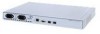
Numbers (continued) Model Port Configuration Power Supply Configuration WX4400 Four dual-interface gigabit installed in a standard 48.26-cm (19-inch) equipment rack or on a tabletop. Figure 1 shows the features of a WX2200 switch. Figure 1 3Com WX2200 Switch Power supplies Serial console - 3Com WX2200 | Hardware Installation Guide - Page 11
Hardware Features 11 WXR100 Switch A WXR100 switch is compact and can be installed on a tabletop. Figure 2 shows the external hardware features of an WXR100 switch. Figure 2 3Com WXR100 Switch CAUTION: Do not stack WXR100 switches. Stacked WXR100 switches can overheat and cause loss of equipment - 3Com WX2200 | Hardware Installation Guide - Page 12
is one RU high and can be installed in a standard 48.26-cm (19-inch) equipment rack or on a tabletop. Figure 3 shows the external hardware features of a WX1200 switch. Figure 3 3Com WX1200 Switch-Control Features Power supply Serial console port Power supply LED 10/100 Ethernet 10/100 and - 3Com WX2200 | Hardware Installation Guide - Page 13
of a WX4400 switch. Figure 4 3Com WX4400 Switch-Control Features Power supply LED Power supply Serial Flash Eject Mgmt console port card slot button LED 100-240V 50/60 Hz 8A MAX DISCONNECT ALL POWER BEFORE SERVICING Console Mgmt AC power inlet Power supply GBIC slot serial number Gigabit - 3Com WX2200 | Hardware Installation Guide - Page 14
one 100-120 VAC / 200-240 VAC autosensing AC power supply. The WX1200 power supply is a fixed-configuration supply and cannot be inserted or removed. A WX2200 switch contains two 100-240V VAC autosensing AC power supplies. A WXR100 switch uses an external power supply, which comes with the switch. - 3Com WX2200 | Hardware Installation Guide - Page 15
standard. On the WXR100, port 2 can be configured for MAP access points and can support Power over Ethernet (PoE). Port 1 is an uplink port only and does not support PoE. On the WX1200, ports 1 through 6 can be configured for MAP access points and can support PoE. Ports 7 and 8 on the WX1200 switch - 3Com WX2200 | Hardware Installation Guide - Page 16
, see Figure 3 and Figure 4.) Table 4 WX1200, WX4400, and WX2200 Status LEDs LED Mgmt (WX4400 and WX2200 only) Power supply status Gigabit fiber link activity (WX4400 and WX2200 only) Gigabit copper link activity (WX4400 and WX2200 only) Link (WX1200 only) Appearance Meaning Bright green, then - 3Com WX2200 | Hardware Installation Guide - Page 17
17 Table 4 WX1200, WX4400, and WX2200 Status LEDs (continued) LED MAP ( problem. Port is not configured as a MAP access port, or PoE is off. WXR100 LEDs Figure 5 shows the locations of the WXR100 LEDs. Table 5 describes the LEDs. Figure 5 WXR100 LEDs FN LED MAP LED 1 2 Link LED Power supply - 3Com WX2200 | Hardware Installation Guide - Page 18
power. Solid green 100-Mbps link is operational. Solid amber 10-Mbps link is operational. Blinking green Traffic is active on the 100-Mbps link. Blinking amber Traffic is active on the 10-Mbps link. Solid green The switch is booting and is loading its configuration or configuration attempt - 3Com WX2200 | Hardware Installation Guide - Page 19
Mobility System Software (MSS) provides a combination of standard wired LAN features and wireless LAN features that enable you to integrate the switch into your wired network and provide network access for wired or wireless users. Management Features „ Serial and network command-line interface - 3Com WX2200 | Hardware Installation Guide - Page 20
authorization attributes that assign VLAN membership, access control, and roaming boundaries. „ Local and remote authentication-You can authenticate users locally using information configured on the WX switch, or use a Remote Authentication Dial-In User Service (RADIUS) server. When you use a remote - 3Com WX2200 | Hardware Installation Guide - Page 21
Software Features 21 RF Management „ RF Auto-Tuning-MSS can automatically assign channels and power settings to MAP access points based on RF information collected from the network. „ Radio frequency (RF) topology-With 3Com Wireless Switch Manager, you can verify site coverage and capacity. „ - 3Com WX2200 | Hardware Installation Guide - Page 22
22 CHAPTER 1: WX SWITCH OVERVIEW - 3Com WX2200 | Hardware Installation Guide - Page 23
installing a WX switch, you might need to generate a network plan with 3Com Wireless Switch Manager. (See "3Com Wireless Switch Manager Network Plan" on page 25.) The shipping carton for a WX switch contains the following items: „ One WX switch, containing one power supply (except for the WX2200 - 3Com WX2200 | Hardware Installation Guide - Page 24
AND CONNECTING A WX SWITCH Figure 6 WX4400 Switch Shipping Carton Contents WX switch with installed power supply Documentation pack Serial cable Power cord Rack-mount brackets Rubber feet Before you begin installation: 1 Open the carton and carefully remove the contents, if you have not - 3Com WX2200 | Hardware Installation Guide - Page 25
. (For information about installing 3Com Wireless Switch Manager and creating and verifying a network plan, see the Wireless LAN Switch Manager Reference Manual.) Installation Location WX4400 switch fans and air inlets are located on the sides of the switch. WX1200 and WX2200 switch fans are - 3Com WX2200 | Hardware Installation Guide - Page 26
To avoid installation problems, use the proper cables. WARNING: The gigabit Ethernet fiber-optic interfaces use Class 1 lasers. To reduce the risk of eye injury, do not stare into the interface or otherwise direct the laser beam into your eye. Serial Console Cable The serial console port has - 3Com WX2200 | Hardware Installation Guide - Page 27
Installation Requirements and feet) The WX1200 supports 10/100 Ethernet connections. Table 8 lists the link type and properties of the supported connections. Table 8 Ethernet 4, 5, 7, and 8 are used only when Power over Ethernet (PoE) is enabled on the port. RD means Receive Data and TD - 3Com WX2200 | Hardware Installation Guide - Page 28
28 CHAPTER 2: INSTALLING AND CONNECTING A WX SWITCH Table 9 10/100 Ethernet Straight-Through Pin Signals WX Switch Pin 1 2 3 4 5 straight-through or crossover. The port automatically configures its pin signals accordingly. PoE is not supported on 1000BASE-TX links. All wires in the cable are used - 3Com WX2200 | Hardware Installation Guide - Page 29
depend on the equipment rack. Power cords Serial console cable Four adhesive rubber feet Power cord(s) Serial console cable Included with the Product Yes No Yes (one) Yes Yes Yes Yes WARNING: To reduce the risk of equipment damage, make sure the WX switch is installed so that the mechanical load - 3Com WX2200 | Hardware Installation Guide - Page 30
feet for tabletop mounting. The WX4400 mounting brackets support either front or center mounting. The WX1200 and WX2200 mounting brackets support front mounting only. The WXR100 switch does not have rack mounting brackets but can be installed on a tabletop. To install a WX switch, use one of the - 3Com WX2200 | Hardware Installation Guide - Page 31
-mount equipment rack. „ Figure 7 shows how to install a WX4400 switch into a front-mount equipment rack. (Installation of a WX1200 or WX2200 switch is similar.) „ Figure 8 shows how to install a WX4400 switch into a center-mount equipment rack. Refer to these figures as you perform the procedure - 3Com WX2200 | Hardware Installation Guide - Page 32
Equipment Rack First, attach brackets to chassis. Then, install chassis into rack. 1 Remove the four bracket screws from to secure the brackets to the WX switch. 4 Repeat for the other bracket. WARNING: 3Com recommends that you ask someone to assist you with the remaining steps. If you accidentally - 3Com WX2200 | Hardware Installation Guide - Page 33
. 7 Do one of the following: „ If you are installing a second power supply into the switch, go to "Installing a Power Supply in a WX4400 Switch" on page 34. „ If you are ready to turn on power, go to "Powering On a WX Switch" on page 37. Tabletop Installation 1 On a clean work surface with no debris - 3Com WX2200 | Hardware Installation Guide - Page 34
a single 100-240 VAC autosensing AC power supply. One power supply provides enough power for a fully configured system. You can add a second power supply for load sharing and redundancy. A WX4400 switch containing one power supply can have the supply installed in either slot. If the switch contains - 3Com WX2200 | Hardware Installation Guide - Page 35
Installing a Power Supply in a WX4400 Switch 35 Figure 9 Inserting a Power Supply in a WX4400 Switch 5 Tighten the thumbscrew using a #2 Phillips-head screwdriver. 6 Go to "Powering On a WX Switch" on page 37. Replacing a Power Supply 1 Remove the power cord from the power supply. 2 Loosen the - 3Com WX2200 | Hardware Installation Guide - Page 36
36 CHAPTER 2: INSTALLING AND CONNECTING A WX SWITCH Figure 10 Removing a Power Supply from a WX4400 Switch Loosen thumbscrew 4 Place your other hand under the supply to support it and remove the supply the rest of the way out of the slot. 5 Go to step 3 of "Installing a New Power Supply" on page 34. - 3Com WX2200 | Hardware Installation Guide - Page 37
PoE devices. To power on a WX1200, WX4400, or WX2200 switch: 1 Make sure any power supply is fully seated in the WX switch. 2 For each power supply that you are using on the WX switch, attach a power cord to an AC power source. 3 Plug the power cord into the WX power supply. The WX switch begins - 3Com WX2200 | Hardware Installation Guide - Page 38
is already powered on, press Enter three times to display a command prompt. For example: WX1200> See "Using the quickstart Command (any model)" of the "Mobility System Software Quick Start Guide" for instructions. „ If a command prompt does not appear, go to "Troubleshooting a Serial Management - 3Com WX2200 | Hardware Installation Guide - Page 39
the WX switch is powered on. 2 Verify that the serial cable is fully inserted in the PC and WX switch ports. 3 Verify that the correct modem settings are configured in the terminal emulation application: „ 9600 bps „ 8 bits „ 1 stop „ No parity „ Hardware flow control disabled 4 Verify that - 3Com WX2200 | Hardware Installation Guide - Page 40
WX1200, and WX2200 switches provide automatic MDI/MDX. 2 If the cable is directly attached to a MAP access point: „ For a first-time installation, set the port type to activate the link. (For information, see "Setting the Port Type" in the Wireless LAN Switch and Controller Configuration Guide. „ If - 3Com WX2200 | Hardware Installation Guide - Page 41
through the WX switch to access the network: „ For a first-time installation, set the port type to activate the link. (For information, see "Setting a Port for a Wired Authentication User" in the Wireless LAN Switch and Controller Configuration Guide.) „ If the port type is already set for a wired - 3Com WX2200 | Hardware Installation Guide - Page 42
2 Access the command-line interface (CLI) on the switch, use the enable command to enter configuration mode, and use the following command to set the 1000BASE-LX cable. Figure 13 shows how to install a GBIC Figure 14 shows how to remove one. Refer to these figures as you perform the procedures - 3Com WX2200 | Hardware Installation Guide - Page 43
Connecting to the Network 43 Figure 14 GBIC Removal from a WX4400 Switch Squeeze the lock clips to release GBIC. To install a GBIC: 1 Insert the GBIC into a GBIC slot on the front panel until it clicks into place. 2 Remove the protective covering(s) from the port connector(s) and - 3Com WX2200 | Hardware Installation Guide - Page 44
a mini-GBIC. Figure 16 shows how to remove one. Refer to these figures as you perform the procedures. (For cable requirements, see "Network Cables" on page 26.) Figure 15 Mini-GBIC Installation in WX2200 Switch Figure 16 Mini-GBIC removal from WX2200 Switch Mini-GBIC Grasp bail latch and pull to - 3Com WX2200 | Hardware Installation Guide - Page 45
Connecting to the Network 45 To install a mini-GBIC: 1 Insert the mini-GBIC into a mini-GBIC slot on the front panel until it clicks into place. 2 Remove the protective covering(s) from the - 3Com WX2200 | Hardware Installation Guide - Page 46
46 CHAPTER 2: INSTALLING AND CONNECTING A WX SWITCH - 3Com WX2200 | Hardware Installation Guide - Page 47
Wireless switch model WXR100 „ Table 14 - Wireless switch model WX2200 Table 11 WX4400 Mechanical and Compliance Specifications Specification Size Weight Operating Temperature Storage Temperature Humidity Power supply 50-A peak inrush current Hot-swappable Load sharing with two supplies installed - 3Com WX2200 | Hardware Installation Guide - Page 48
Wired network ports Safety and electromagnetic compliance Description Management CPU status LED Power supply status LEDs Port activity and link speed LEDs (For descriptions of the LEDs, see "WX1200, WX4400, and WX2200 Status LEDs" on page 16.) Four dual-interface gigabit Ethernet ports. Each - 3Com WX2200 | Hardware Installation Guide - Page 49
(continued) Specification Status indicators Wired network ports Safety and electromagnetic compliance Description Power supply status LEDs Port activity and link speed LEDs (For descriptions of the LEDs, see "WX1200, WX4400, and WX2200 Status LEDs" on page 16.) Six RJ-45 ports for 10/100BASE - 3Com WX2200 | Hardware Installation Guide - Page 50
EN 60950 EN 60101-1-2 EU Medical Directive CISPR 22 Class B VCCI Class B Table 14 WX2200 Mechanical and Compliance Specifications Specification Size Weight Operating Temperature Storage Temperature Humidity Power supply Status indicators Description Width: 44.2 cm (17.4 inches) Depth: 30.7 cm (12 - 3Com WX2200 | Hardware Installation Guide - Page 51
51 Table 14 WX2200 Mechanical and Compliance Specifications (continued) Specification Wired network ports Safety and electromagnetic compliance Description Two miniature gigabit interface converter (mini-GBIC) slots for 1000BASE-SX, - 3Com WX2200 | Hardware Installation Guide - Page 52
52 CHAPTER A: WX TECHNICAL SPECIFICATIONS - 3Com WX2200 | Hardware Installation Guide - Page 53
LAN Switch and Controller Configuration Guide.) 3 Reconfigure the administrative certificate(s). (See "Creating Keys and Certificates" in the Wireless LAN Switch and Controller Configuration Guide.) 4 If you have already configured a certificate on the switch for authentication by network users - 3Com WX2200 | Hardware Installation Guide - Page 54
in which you are operating the switch, use the set system countrycode command to configure the correct country code. (See "Specifying the Country of Operation" in the Wireless LAN Switch and Controller Configuration Guide.) Client cannot access This symptom has more the network. than one possible - 3Com WX2200 | Hardware Installation Guide - Page 55
Table 15 WX Setup Problems and Remedies (continued) Symptom Diagnosis Remedy Configuration information disappears after a software reload. The configuration changes 1 Retype the commands for the were not saved. missing configuration information. 2 Type the save config command to save the - 3Com WX2200 | Hardware Installation Guide - Page 56
56 CHAPTER B: WX TROUBLESHOOTING - 3Com WX2200 | Hardware Installation Guide - Page 57
C OBTAINING SUPPORT FOR YOUR 3COM PRODUCTS Register Your Product to Gain Service Benefits Solve Problems Online 3Com offers product registration, case management, and repair services through eSupport.3com.com. You must have a user name and password to access these services, which are described in - 3Com WX2200 | Hardware Installation Guide - Page 58
product. Separately orderable software releases and licenses are listed in the 3Com Price List and are available for purchase from your 3Com reseller. Contact Us 3Com offers telephone, internet, and e-mail access to technical support and repair services. To access these services for your region - 3Com WX2200 | Hardware Installation Guide - Page 59
other service Support and Repair benefits, you must first register your product at: http://eSupport.3com.com/ When you contact 3Com for assistance, please have the following information ready: ■ Product model name, part number, and serial number ■ A list of system hardware and software, including - 3Com WX2200 | Hardware Installation Guide - Page 60
6780 Vietnam Call the U.S. direct by dialing 1 201 0288, then dialing 800 763 6780 You can also obtain non-urgent support in this region at this email address [email protected] Or request a return material authorization number (RMA) by FAX using this number: +61 2 9937 5048, or send an - 3Com WX2200 | Hardware Installation Guide - Page 61
Contact Us 61 Country Telephone Number Country US and Canada - Telephone Technical Support and Repair All locations: Network Jacks; Wired or Wireless Network Interface Cards: All other 3Com products: Telephone Number 1 847-262-0070 1 800 876 3266 - 3Com WX2200 | Hardware Installation Guide - Page 62
62 APPENDIX C: OBTAINING SUPPORT FOR YOUR 3COM PRODUCTS - 3Com WX2200 | Hardware Installation Guide - Page 63
Services 58 3Com resources, directory 59 3WXM network plan 25 A AC power inlet 14 authentication failure, troubleshooting 54 B booting 37 bug fixes 58 C cables network 26 serial console 26 certificates invalid, troubleshooting 53 clients, no network access, troubleshooting 54 configuration - 3Com WX2200 | Hardware Installation Guide - Page 64
15 power supplies 14 installation, WX4400 34 LEDs 16 powering on 37 product registration 57, 58 Professional Services from 3Com 58 purchasing license keys 58 purchasing software upgrades 58 R rack mount installation 31 radios denial of configuration information, troubleshooting 54 registering - 3Com WX2200 | Hardware Installation Guide - Page 65
links 39 incomplete boot load 55 installation and setup 53 invalid certificate 53 missing configuration 55 serial console 39 U users, no network access, troubleshooting 54 V VLANs (virtual LANs) authorization failure, troubleshooting 54 disconnected, troubleshooting 54 W warnings earth grounding 30 - 3Com WX2200 | Hardware Installation Guide - Page 66
66 INDEX
-
 1
1 -
 2
2 -
 3
3 -
 4
4 -
 5
5 -
 6
6 -
 7
7 -
8
-
9
-
10
-
11
-
12
-
13
-
14
-
15
-
16
-
17
-
18
-
19
-
20
-
21
-
22
-
23
-
24
-
25
-
26
-
27
-
28
-
29
-
30
-
31
-
32
-
33
-
34
-
35
-
36
-
37
-
38
-
39
-
40
-
41
-
42
-
43
-
44
-
45
-
46
-
47
-
48
-
49
-
50
-
51
-
52
-
53
-
54
-
55
-
56
-
57
-
58
-
59
-
60
-
61
-
62
-
63
-
64
-
65
-
66
 |
 |

Part No. 10015410 Rev. AA
Published August 2006
Wireless LAN Mobility System
Wireless LAN Switch and Controller
Hardware Installation Guide
WX4400
3CRWX440095A
WX1200
3CRWX120695A
WXR100
3CRWXR10095A
WX2200
3CRWX220095A