ASRock 4Core1333-Viiv User Manual
ASRock 4Core1333-Viiv Manual
 |
View all ASRock 4Core1333-Viiv manuals
Add to My Manuals
Save this manual to your list of manuals |
ASRock 4Core1333-Viiv manual content summary:
- ASRock 4Core1333-Viiv | User Manual - Page 1
4Core1333-Viiv User Manual Version 1.0 Published June 2007 Copyright©2007 ASRock INC. All rights reserved. 1 - ASRock 4Core1333-Viiv | User Manual - Page 2
may appear in this manual. With respect to the contents of this manual, ASRock does not provide warranty of any kind, either expressed or implied, including but CALIFORNIA, USA ONLY The Lithium battery adopted on this motherboard contains Perchlorate, a toxic substance controlled in Perchlorate Best - ASRock 4Core1333-Viiv | User Manual - Page 3
Windows® VistaTM Premium 2007 and Basic Logo 9 1.4 Minimum Hardware Requirement Table for Intel® ViivTM Technology 10 1.5 Motherboard Layout 11 1.6 ASRock 1394_eSATAII I/O Plus 12 1.7 ASRock Plug Feature and Operation Guide 44 2.18 Driver Installation Guide 46 2.19 Installing Windows® 2000 / XP - ASRock 4Core1333-Viiv | User Manual - Page 4
Windows® VistaTM / VistaTM 64-bit Without RAID Functions 51 2.21 Untied Overclocking Technology 51 3 BIOS SETUP UTILITY 52 3.1 Introduction 52 3.1.1 BIOS 4 Software Support 68 4.1 Install Operating System 68 4.2 Support CD Information 68 4.2.1 Running Support CD 68 4.2.2 Drivers Menu 68 - ASRock 4Core1333-Viiv | User Manual - Page 5
of this manual occur, the updated version will be available on ASRock website without further notice. You may find the latest VGA cards and CPU support lists on ASRock website as well. ASRock website http://www.asrock.com 1.1 Package Contents ASRock 4Core1333-Viiv Motherboard (ATX Form Factor - ASRock 4Core1333-Viiv | User Manual - Page 6
CPU Chipset Memory Hybrid Booster Expansion Slot Audio LAN Rear Panel I/O - ATX Form Factor: 12.0-in x 9.0-in, 30.5 cm x 22.9 cm - LGA 775 for Intel® CoreTM 2 Quad / CoreTM 2 Extreme / CoreTM 2 Duo / Pentium® XE / Pentium® D / Pentium® Dual Core / Pentium® 4 / Celeron® / Celeron® D, supporting - ASRock 4Core1333-Viiv | User Manual - Page 7
x IEEE 1394 header - CPU/Chassis FAN connector - 20 pin ATX power connector - 4 pin 12V power connector - SLI/XFIRE power connector - CD in header - Front panel audio connector - 3 x USB 2.0 headers (support 6 USB 2.0 ports) (see CAUTION 13) - 4Mb AMI BIOS - AMI Legal BIOS - Supports "Plug and Play - ASRock 4Core1333-Viiv | User Manual - Page 8
. We are not responsible for possible damage caused by overclocking. CAUTION! 1. FSB1333-CPU will operate in overclocking mode. 2. Intel® ViivTM technology is only supported under 32-bit OS of Windows® XP Media Center and Windows® VistaTM Home Premium and Ultimate Edition. For the minimum - ASRock 4Core1333-Viiv | User Manual - Page 9
our website for Microsoft® Windows® VistaTM / VistaTM 64-bit driver and related information. ASRock website http://www.asrock.com 1.3 Minimum Hardware Requirement Table for Windows® VistaTM Premium 2007 and Basic Logo For system integrators and users who purchase this motherboard and plan to submit - ASRock 4Core1333-Viiv | User Manual - Page 10
® XP 32-bit Media Center or Windows® VistaTM 32-bit Home Premium and Ultimate Edition * Currently, Intel® ViivTM technology requires Intel® Dual Core CPU or above except Intel® Pentium® Dual Core E2XXX CPU. For further information of CPU support list, please refer to Intel® website for updates. 10 - ASRock 4Core1333-Viiv | User Manual - Page 11
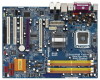
1394 USB 2.0 T: USB0 B: USB1 Top: RJ-45 FSB1333 Intel P965 Chipset IDE1 RAID RoHS SLI/XFIRE_PWR1 USB2.0 Gigabit LAN eSATAII ATXPWR1 Top: LINE IN Center: FRONT Bottom: MIC IN 7.1CH HD PCI PCIE1 EXPRESS 4Core1333-Viiv ATA133 LAN PHY PCIE2 1394a SATAII 1 AGI_EXPRESS1 PCIEX1_EN1 - ASRock 4Core1333-Viiv | User Manual - Page 12
1.6 ASRock 1394_eSATAII I/O Plus 1 PS/2 Mouse Port (Green) 2 Parallel Port 3 IEEE 1394 Port 4 RJ-45 Port 5 Side Speaker (Gray) 6 Rear Speaker (Black) 7 Central / Bass (Orange) 8 Line In ( - ASRock 4Core1333-Viiv | User Manual - Page 13
and one Express card slot to support all kinds of Express cards, such as eSATAII card, USB 2.0 card, LAN card and flash disc, offers you a device to expand the availability conveniently in addition to the PCI Express interface on this motherboard. Please refer to below table for ASRock DeskExpress - ASRock 4Core1333-Viiv | User Manual - Page 14
4Core1333-Viiv is an ATX form factor (12.0" x 9.0", 30.5 x 22.9 cm) motherboard. Before you install the motherboard, study the configuration of your chassis to ensure that the motherboard fits into it. Make sure to unplug the power cord before installing or removing the motherboard. Failure - ASRock 4Core1333-Viiv | User Manual - Page 15
Installation For the installation of Intel 775-LAND CPU, please follow the steps below. 775-Pin Socket Overview Before you insert the 775-LAND CPU into the socket, please check if the CPU surface is unclean or if there is any bent pin on the socket. Do not force to insert the CPU into the socket if - ASRock 4Core1333-Viiv | User Manual - Page 16
CPU is within the socket and properly mated to the orient keys. Step 3. Remove PnP Cap (Pick and Place Cap): Use your left hand index finger and thumb to support PnP cap. 2. This cap must be placed if returning the motherboard for after service. Step 4. Close the socket: Step 4-1. Rotate the load - ASRock 4Core1333-Viiv | User Manual - Page 17
Heatsink This motherboard is equipped with 775-Pin socket that supports Intel 775-LAND CPU. Please adopt the type of heatsink and cooling fan compliant with Intel 775-LAND CPU to dissipate heat. Before you installed the heatsink, you need to spray thermal interface material between the CPU and the - ASRock 4Core1333-Viiv | User Manual - Page 18
Memory Modules (DIMM) 4Core1333-Viiv motherboard provides four 240-pin DDRII (Double Data Rate II) DIMM slots, and supports Dual Channel Memory slot; otherwise, this motherboard and DIMM may be damaged. 5. If you plan to use ATITM PCI Express VGA card on this motherboard, the total system memory - ASRock 4Core1333-Viiv | User Manual - Page 19
matches the break on the slot. notch break notch break The DIMM only fits in one correct orientation. It will cause permanent damage to the motherboard and the DIMM if you force the DIMM into the slot at incorrect orientation. Step 3. Firmly insert the DIMM into the slot until the retaining - ASRock 4Core1333-Viiv | User Manual - Page 20
1 AGI Express slot (PCI Express x4) on this motherboard. PCI slots: PCI slots are used to install expansion cards that have the 32-bit PCI interface. PCIE slots: PCIE1 (PCIE x1 slot) is used for PCI Express cards with x1 lane width cards, such as Gigabit LAN card, SATA2 card and ASRock PCIE_DE card - ASRock 4Core1333-Viiv | User Manual - Page 21
Installing an expansion card Step 1. Before installing the expansion card, please make sure that the power supply is switched off or the power cord is unplugged. Please read the documentation of the expansion card and make necessary hardware settings for the card before you start the installation. - ASRock 4Core1333-Viiv | User Manual - Page 22
DeskExpress Installation Guide This motherboard supports ASRock DeskExpress, providing PCI Express slot for one front USB 2.0 port and all kinds of PCI Express interface cards, such as eSATAII card, USB 2.0 card, LAN card and flash disc. ASRock DeskExpress provides a device for you to expand the - ASRock 4Core1333-Viiv | User Manual - Page 23
to PCIE1 slot on this motherboard. For the proper installation of ASRock PCIE_DE card, please refer to the installation guide on page 20. ASRock PCIE_DE card PCIE1 slot Step 2. Connect either end of SATA data cable to PCIE1 (yellow) / PCIE2 (white) port on ASRock PCIE_DE card. PCIE2 port (white - ASRock 4Core1333-Viiv | User Manual - Page 24
Boot your system. Step 10. The function of ASRock DeskExpress is enabled. You can insert your USB flash drive or any PCI Express interface card to ASRock DeskExpress. (USB flash drive and PCI Express interface card are not bundled with this motherboard. Please refer to the product vendor for related - ASRock 4Core1333-Viiv | User Manual - Page 25
supported with Windows® XP with Service Pack 2. Please check ATITM website for driver updates. What graphics cards work with CrossFireTM? A complete CrossFireTM system requires a CrossFireTM Ready motherboard future, please refer to ATITM graphics card manuals for detailed installation guide. 25 - ASRock 4Core1333-Viiv | User Manual - Page 26
motherboard to enable AGI Express slot (PCI Express x4). Please refer to the pictures below for proper jumper setting. PCIEX1_EN1-5: Short Pin1, Pin2 Step 2. Connect to the system power supply. Please connect a hard disk power connector to SLI Express slot (PCI Express x4) to support CrossFireTM. Besides - ASRock 4Core1333-Viiv | User Manual - Page 27
other end to DVI of another CrossFireTM Edition graphics card to AGI Express slot (PCI Express x4). If you install one CrossFireTM Edition graphics card and one compatible standard Radeon (CrossFireTM Ready) graphics card to this motherboard, please connect one end of DVI-DMS cable to the monitor - ASRock 4Core1333-Viiv | User Manual - Page 28
: http://support.ati.com/ics/support/DLRedirect.asp? fileIDExt=050553d40196ef109fff37cbb40aaf28&accountID=737&deptID=894 Step 8. Install the required drivers to your system. Please visit the websites below for installing the drivers that ATITM recommends: A. ATITM recommends Windows® XP Service Pack - ASRock 4Core1333-Viiv | User Manual - Page 29
without intent to infringe. 2.9 Surround Display Feature This motherboard supports Surround Display upgrade. With the external add-on PCI Express VGA card, you can easily enjoy the benefits of Surround Display feature. For the detailed instruction, please refer to the document at the following path - ASRock 4Core1333-Viiv | User Manual - Page 30
when you just finish updating the BIOS, you must boot up the system first, and then shut it down before you do the clear-CMOS action. PCIEX1_EN1-5 (see p.11 No. 12) Default 2_3 1_2 Short pin2, pin3 to enable onboard IDE connector (IDE1) and disable AGI Express slot (PCI Express x4). Short pin1 - ASRock 4Core1333-Viiv | User Manual - Page 31
the black end to the motherboard to the IDE devices 80-conductor ATA 66/100 cable Note: Please refer to the instruction of your IDE device vendor for internal storage device or be connected to eSATAII connector to support eSATAII device. Please read "eSATAII Interface Introduction" on page 38 - ASRock 4Core1333-Viiv | User Manual - Page 32
ASRock DeskExpress on this motherboard, please connect PCIE1 / PCIE2 port on ASRock PCIE_DE card and PCIE1 / PCIE2 port on ASRock No. 34) CD1 CD-L GND GND CD-R This header supports the Hot Plug detection function for ASRock DeskExpress. This connector allows you to receive stereo audio input - ASRock 4Core1333-Viiv | User Manual - Page 33
allows convenient connection and control of audio devices. 1. High Definition Audio supports Jack Sensing, but the panel wire on the chassis must support HDA to function correctly. Please follow the instruction in our manual and chassis manual to install your system. 2. If you use AC'97 audio - ASRock 4Core1333-Viiv | User Manual - Page 34
For Windows® VistaTM / VistaTM 64-bit support, the 3-Pin CPU fan still can work successfully even without the fan speed control function. If you plan to connect the 3-Pin CPU fan to the CPU fan connector on this motherboard, please connect it to Pin 1-3. Pin 1-3 Connected 3-Pin Fan Installation ATX - ASRock 4Core1333-Viiv | User Manual - Page 35
SLI/XFIRE_POWER1) (see p.11 No. 4) SLI/XFIRE_POWER1 It is not necessary to use this connector, but please connect it with a hard disk power connecor when two graphics cards are plugged to this motherboard header (FRONT_1394) on this motherboard. This IEEE 1394 header can support one IEEE 1394 port. - ASRock 4Core1333-Viiv | User Manual - Page 36
SPDIFOUT GND blue black SPDIFOUT GND blue black SPDIFOUT GND blue black DeskExpress Hot Plug Detection Cable (Optional) If you use ASRock DeskExpress on this motherboard, please connect either end of DeskExpress Hot Plug detection cable to DeskExpress Hot Plug detection header (IR1) on this - ASRock 4Core1333-Viiv | User Manual - Page 37
, please carefully follow the below steps. Step 1. Install the HDMI VGA card to the• PCI Express Graphics slot on this motherboard. For the proper installation of HDMI VGA card, please refer to the installation guide on page 20. Step 2. Connect the black end (A) of HDMI_SPDIF cable to the HDMI_SPDIF - ASRock 4Core1333-Viiv | User Manual - Page 38
eSATAII Interface Introduction What is eSATAII? This motherboard supports eSATAII interface, the external SATAII specification. . 2. If you set "Configure SATAII as" option in BIOS setup to IDE mode, Hot Plug function is not supported with eSATAII devices. If you still want to use eSATAII function - ASRock 4Core1333-Viiv | User Manual - Page 39
1. In order to enable the eSATAII port of the I/O shield, you need to connect the orange SATAII connector (SATAII_6 (Port5); see p.11 No.22) and the eSATAII connector (eSATAII; see p.11 No.38) with a SATA data cable first. Connect the SATA data cable to the orange SATAII connector (SATAII_6 (Port5 - ASRock 4Core1333-Viiv | User Manual - Page 40
Comparison between eSATAII and other devices IEEE 1394 USB 2.0 SATA eSATAII/SATAII 400Mb/s 480Mb/s 1.5Gb/s (1500Mb/s) 3.0Gb/s (3000Mb/s) 40 - ASRock 4Core1333-Viiv | User Manual - Page 41
guide. Some default setting of SATAII hard disks may not be at SATAII mode, which operate with the best performance. In order to enable SATAII function, please follow the below instruction 's website for details: http://www.hitachigst.com/hdd/support/download.htm The above examples are just for your - ASRock 4Core1333-Viiv | User Manual - Page 42
south bridge chipset that supports Serial ATA (SATA) / Serial ATAII (SATAII) hard disks and RAID (RAID 0, RAID 1, RAID 10, RAID 5, and Intel Matrix Storage) functions. You may install SATA / SATAII hard disks on this motherboard for internal storage devices. This section will guide you to install - ASRock 4Core1333-Viiv | User Manual - Page 43
Functions for SATA / SATAII HDDs and eSATAII Devices This motherboard supports Hot Plug and Hot Swap functions for SATA / SATAII / eSATAII Devices in RAID mode. Intel® ICH8DH south bridge chipset provides hardware support for Advanced Host controller Interface (AHCI), a new programming interface - ASRock 4Core1333-Viiv | User Manual - Page 44
Guide This motherboard supports Hot Plug feature for SATA / SATAII HDD. Please read below operation guide of driver is available on our support website: www.asrock.com 4. Make sure to use the SATA power cable & data cable, which are from our motherboard package. 5. Please follow below instructions - ASRock 4Core1333-Viiv | User Manual - Page 45
cable to (White) to the power supply 1x4-pin cable. the motherboard's SATAII connector. SATA power cable 1x4-pin power connector (White) Step attention, before you process the Hot Unplug: Please do follow below instruction sequence to process the Hot Unplug, improper procedure will cause the SATA - ASRock 4Core1333-Viiv | User Manual - Page 46
to bottom side to install those required drivers. Therefore, the drivers you install can work properly. If you install Windows® XP 64-bit OS, there may be a "!" mark on the item "USB Root Hub" in "Device Manager" after you install "Intel Viiv Driver" from our support CD. Please follow below steps to - ASRock 4Core1333-Viiv | User Manual - Page 47
in the support CD, "Guide to Intel Matrix Storage Manager", which is located in the folder at the following path: .. \ Intel Matrix Storage Manager Information If you want to use "Intel Matrix Storage Manager" in Windows® environment, please install SATA / SATAII drivers from the Support CD again - ASRock 4Core1333-Viiv | User Manual - Page 48
/ DO/DH SATA RAID Controller (Desktop ICH8R-Windows XP64)" for Windows® XP 64-bit. 5. Finish the Windows® installation and install all necessary drivers. 6. Install the Intel(R) Matrix Storage Manager software via the CD-ROM included with your motherboard or after downloading it from the Internet - ASRock 4Core1333-Viiv | User Manual - Page 49
the instruction to install Windows® VistaTM / VistaTM 64-bit OS on your system. When you see "Where do you want to install Windows?" page, please insert the ASRock Support CD into your optical drive, and click the "Load Driver" button on the left on the bottom to load the Intel® RAID drivers. Intel - ASRock 4Core1333-Viiv | User Manual - Page 50
system. At the beginning of Windows® setup, press F6 to install a third-party AHCI driver. When prompted, insert the SATA / SATAII driver diskette containing the Intel® AHCI driver. After reading the floppy disk, the driver will be presented. Select the driver to install according to the mode - ASRock 4Core1333-Viiv | User Manual - Page 51
64-bit OS on your system. After setting up BIOS, you can start to install Windows® VistaTM / VistaTM 64-bit on your system. 2.21 Untied Overclocking Technology This motherboard supports Untied Overclocking Technology, which means during overclocking, FSB enjoys better margin due to fixed PCI - ASRock 4Core1333-Viiv | User Manual - Page 52
BIOS FWH chip on the motherboard stores the BIOS SETUP UTILITY. You may run the BIOS SETUP UTILITY when you start up the computer. Please press during the Power-On-Self-Test (POST) to enter the BIOS on. Because the BIOS software is constantly being updated, the following BIOS setup screens and - ASRock 4Core1333-Viiv | User Manual - Page 53
System Overview System Time System Date [14:00:09] [Tue 06/05/2007] BIOS Version : 4Core1333-Viiv BIOS P1.00 Processor Type : Intel (R) Core (TM) 2 CPU 6600 @ 2.40GHz (64bit) Processor Speed : 2400MHz Microcode Update : 6F6/C6 Cache Size : 4096KB Total Memory DDRII 1 DDRII 2 DDRII 3 DDRII - ASRock 4Core1333-Viiv | User Manual - Page 54
BIOS SETUP UTILITY Advanced CPU Configuration Overclock Mode CPU Frequency (MHz) PCIE Frequency (MHz) Boot Failure Guard Spread Spectrum Ratio Actual Value Enhanced Halt State Intel (R) Virtualization tech. CPU Thermal Throttling No-Excute Memory Protection Intel (R) SpeedStep (tm) tech - ASRock 4Core1333-Viiv | User Manual - Page 55
. Set to [Enabled] if using Microsoft® Windows® XP, or Linux kernel version 2.4.18 or higher. This option will be hidden if the installed CPU does not support Hyper-Threading technology. Intel (R) SpeedStep(tm) tech. Intel (R) SpeedStep(tm) tech. is Intel's new power saving technology. Processor can - ASRock 4Core1333-Viiv | User Manual - Page 56
3.3.2 Chipset Configuration BIOS SETUP UTILITY Advanced Chipset Configuration Memory Remap Feature [Disabled] DRAM default value is [Disabled]. DRAM Frequency If [Auto] is selected, the motherboard will detect the memory module(s) inserted and assigns appropriate frequency automatically. You - ASRock 4Core1333-Viiv | User Manual - Page 57
Adapter This allows you to select [PCI] or [PCI Express] as the boot graphic adapter priority. The default value disable CD-In of OnBoard HD Audio. If you plan to use this motherboard to submit Windows® VistaTM logo test, please disable this option. OnBoard Lan This allows you to enable or disable - ASRock 4Core1333-Viiv | User Manual - Page 58
BIOS Suspend-toRAM feature. Select [Auto] will enable this feature if the OS supports it. If you set this item to [Disabled], the function "Repost Video Lake Feature Use this item to enable or disable energy lake feature under Windows® XP Media Center OS. The default value is [Disabled]. Restore on - ASRock 4Core1333-Viiv | User Manual - Page 59
use this motherboard to submit Windows® VistaTM certification. 3.3.4 IDE Configuration BIOS SETUP UTILITY have these advantages. 2. Only AHCI and RAID modes support Hot Plug function. OnBoard SATAII Controller Use this item instruction, which can be applied to the configurations of "IDE Slave" as - ASRock 4Core1333-Viiv | User Manual - Page 60
BIOS SETUP UTILITY Advanced Primary IDE Master Device Vendor Size LBA Mode Block Mode PIO Mode Async DMA Ultra DMA S.M.A.R.T. Type LBA/Large Mode Block (Multi-Sector Transfer) PIO Mode DMA Mode S.M.A.R.T. 32Bit Data Transfer :Hard Disk :ST340014A :40.0 GB :Supported DOS and Windows; for Netware - ASRock 4Core1333-Viiv | User Manual - Page 61
the time you may wait. Configuration options: [0], [5], [10], [15], [20], [25], [30] and [35]. The default value is [20]. 3.3.5 PCIPnP Configuration BIOS SETUP UTILITY Advanced Advanced PCI / PnP Settings PCI Latency Timer PCI IDE BusMaster [32] [Enabled] Value in units of PCI clocks for PCI - ASRock 4Core1333-Viiv | User Manual - Page 62
Mode DMA Channel Parallel Port IRQ OnBoard Game Port OnBoard MIDI Port [Enabled] [3F8 / IRQ4] [378] [ECP + EPP] [1.9] [DMA3] [IRQ7] [Auto] [Disabled] Allow BIOS to Enable or Disable Floppy Controller. +F1 F9 F10 ESC Select Screen Select Item Change Option General Help Load Defaults Save and Exit - ASRock 4Core1333-Viiv | User Manual - Page 63
Parallel Port Mode Use this item to set the operation mode of the parallel port. The default value is [ECP+EPP]. If this option is set to [ECP+EPP], it will show the EPP version in the following item, "EPP Version". Configuration options: [Normal], [Bi-Directional], and [ECP+EPP]. EPP Version Use - ASRock 4Core1333-Viiv | User Manual - Page 64
3.3.8 USB Configuration BIOS SETUP UTILITY Advanced USB Configuration USB Controller USB 2.0 Support Legacy USB Support [Enabled] [Enabled] [Disabled] To enable or disable the onboard USB controllers. +F1 F9 F10 ESC Select Screen Select Item Change Option General Help Load Defaults - ASRock 4Core1333-Viiv | User Manual - Page 65
you to monitor the status of the hardware on your system, including the parameters of the CPU temperature, motherboard temperature, CPU fan speed, chassis fan speed, and the critical voltage. BIOS SETUP UTILITY Main Advanced H/W Monitor Boot Security Exit Hardware Health Event Monitoring - ASRock 4Core1333-Viiv | User Manual - Page 66
you may set or change the supervisor/user password for the system. For the user password, you may also clear it. BIOS SETUP UTILITY Main Advanced H/W Monitor Boot Security Exit Security Settings Supervisor Password : Not Installed User Password : Not Installed Change Supervisor Password - ASRock 4Core1333-Viiv | User Manual - Page 67
and exit setup?" Select [OK] to save the changes and exit the BIOS SETUP UTILITY. Discard Changes and Exit When you select this option, it message, "Discard changes and exit setup?" Select [OK] to exit the BIOS SETUP UTILITY without saving any changes. Discard Changes When you select this option - ASRock 4Core1333-Viiv | User Manual - Page 68
install the necessary drivers to activate the devices. 4.2.3 Utilities Menu The Utilities Menu shows the applications software that the motherboard supports. Click on a specific item then follow the installation wizard to install it. 4.2.4 Contact Information If you need to contact ASRock or want to
-
 1
1 -
 2
2 -
 3
3 -
 4
4 -
 5
5 -
 6
6 -
 7
7 -
8
-
9
-
10
-
11
-
12
-
13
-
14
-
15
-
16
-
17
-
18
-
19
-
20
-
21
-
22
-
23
-
24
-
25
-
26
-
27
-
28
-
29
-
30
-
31
-
32
-
33
-
34
-
35
-
36
-
37
-
38
-
39
-
40
-
41
-
42
-
43
-
44
-
45
-
46
-
47
-
48
-
49
-
50
-
51
-
52
-
53
-
54
-
55
-
56
-
57
-
58
-
59
-
60
-
61
-
62
-
63
-
64
-
65
-
66
-
67
-
68
 |
 |

1
4Core1333-Viiv
User Manual
Version 1.0
Published June 2007
Copyright©2007 ASRock INC. All rights reserved.