ASRock 4Core1333-eSATA2 User Manual
ASRock 4Core1333-eSATA2 Manual
 |
View all ASRock 4Core1333-eSATA2 manuals
Add to My Manuals
Save this manual to your list of manuals |
ASRock 4Core1333-eSATA2 manual content summary:
- ASRock 4Core1333-eSATA2 | User Manual - Page 1
4Core1333-eSATA2 User Manual Version 5.1 Published December 2007 Copyright©2007 ASRock INC. All rights reserved. 1 - ASRock 4Core1333-eSATA2 | User Manual - Page 2
purchaser for backup purpose, without written consent of ASRock Inc. Products and corporate names appearing in this manual may or may not be registered trademarks or copyrights USA ONLY The Lithium battery adopted on this motherboard contains Perchlorate, a toxic substance controlled in Perchlorate - ASRock 4Core1333-eSATA2 | User Manual - Page 3
6 1.3 Minimum Hardware Requirement Table for Windows® VistaTM Premium 2007 and Basic Logo 9 1.4 Motherboard Layout 10 1.5 ASRock 1394_eSATAII I/O Plus 11 2 Installation 12 2.1 Screw Holes 12 2.2 Pre-installation Precautions 12 2.3 CPU Installation 13 2.4 Installation of Heatsink and - ASRock 4Core1333-eSATA2 | User Manual - Page 4
40 3.1.1 BIOS Menu Bar 40 3.1.2 Navigation Keys 41 3.2 Main Screen 41 3.3 Advanced Screen 41 3.3.1 CPU Configuration 42 Screen 56 4 Software Support 57 4.1 Install Operating System 57 4.2 Support CD Information 57 4.2.1 Running Support CD 57 4.2.2 Drivers Menu 57 4.2.3 Utilities Menu - ASRock 4Core1333-eSATA2 | User Manual - Page 5
guide to BIOS setup and information of the Support CD. Because the motherboard specifications and the BIOS software might be updated, the content of this manual will be subject to change without notice. In case any modifications of this manual occur, the updated version will be available on ASRock - ASRock 4Core1333-eSATA2 | User Manual - Page 6
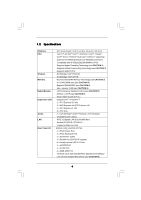
Wolfdale processors - Compatible with all FSB1333/1066/800MHz CPUs - Supports Hyper-Threading Technology (see CAUTION 1) - Supports Untied Overclocking Technology (see CAUTION 2) - Supports EM64T CPU - Northbridge: Intel® P31/G31 - Southbridge: Intel® ICH7R - Dual Channel DDRII Memory Technology - ASRock 4Core1333-eSATA2 | User Manual - Page 7
CAUTION 13) - 4Mb AMI BIOS - AMI Legal BIOS - Supports "Plug and Play" - ACPI 1.1 Compliance Wake Up Events - Supports jumperfree - AMBIOS 2.3.1 Support - Drivers, Utilities, AntiVirus Software (Trial Version) - CPU Temperature Sensing - Chassis Temperature Sensing - CPU Fan Tachometer - Chassis Fan - ASRock 4Core1333-eSATA2 | User Manual - Page 8
Technology. Please read "Untied Overclocking Technology" on page 39 for details. 3. This motherboard supports Dual Channel Memory Technology. Before you implement Dual Channel Memory Technology, make sure to read the installation guide of memory modules on page 16 for proper installation - ASRock 4Core1333-eSATA2 | User Manual - Page 9
and users who purchase this motherboard and plan to submit Windows® VistaTM Premium 2007 and Basic logo, please follow below table for minimum hardware requirements. CPU Memory VGA Celeron D 326 1GB system memory (Premium) 512MB Single Channel (Basic) DX9.0 with WDDM Driver with 128bit VGA memory - ASRock 4Core1333-eSATA2 | User Manual - Page 10
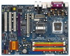
4Core1333-eSATA2 USB 2.0 Top: T: USB2 IEEE B: USB3 1394 FSB1333 USB 2.0 T: USB0 B: USB1 Top: RJ-45 1 1 Intel IDE1 FSB1 FSB2 Top: SIDE SPK Center: REAR SPK Bottom: CTR BASS P31/G31 Chipset eSATAII ATXPWR1 SLI 3 FSB1 / FSB2 Jumpers 4 775-Pin CPU Socket 5 CPU Fan Connector (CPU_FAN1) 6 2 - ASRock 4Core1333-eSATA2 | User Manual - Page 11
1.5 ASRock 1394_eSATAII I/O Plus 1 PS/2 Mouse Port (Green) 2 Parallel Port 3 IEEE 1394 Port 4 RJ-45 Port 5 Side Speaker (Gray) 6 Rear Speaker (Black) 7 Central / Bass (Orange) 8 Line In ( - ASRock 4Core1333-eSATA2 | User Manual - Page 12
4Core1333-eSATA2 is an ATX form factor (12.0" x 9.0", 30.5 x 22.9 cm) motherboard. Before you install the motherboard, study the configuration of your chassis to ensure that the motherboard fits into it. Make sure to unplug the power cord before installing or removing the motherboard. Failure - ASRock 4Core1333-eSATA2 | User Manual - Page 13
the installation of Intel 775-LAND CPU, please follow the steps below. 775-Pin Socket Overview Before you insert the 775-LAND CPU into the socket, please check if the CPU surface is unclean or if there is any bent pin on the socket. Do not force to insert the CPU into the socket if above situation - ASRock 4Core1333-eSATA2 | User Manual - Page 14
to use the cap tab to handle and avoid kicking off the PnP cap. 2. This cap must be placed if returning the motherboard for after service. Step 4. Close the socket: Step 4-1. Rotate the load plate onto the IHS. Step 4-2. While pressing down lightly on load plate, engage the load lever. Step - ASRock 4Core1333-eSATA2 | User Manual - Page 15
Heatsink This motherboard is equipped with 775-Pin socket that supports Intel 775-LAND CPU. Please adopt the type of heatsink and cooling fan compliant with Intel 775-LAND CPU to dissipate heat. Before you installed the heatsink, you need to spray thermal interface material between the CPU and the - ASRock 4Core1333-eSATA2 | User Manual - Page 16
2.5 Installation of Memory Modules (DIMM) 4Core1333-eSATA2 motherboard provides four 240-pin DDRII (Double Data Rate II) DIMM slots, and supports Dual Channel Memory Technology. For dual channel configuration, you always need to install identical (the same brand, speed, size and chip-type) DDRII - ASRock 4Core1333-eSATA2 | User Manual - Page 17
matches the break on the slot. notch break notch break The DIMM only fits in one correct orientation. It will cause permanent damage to the motherboard and the DIMM if you force the DIMM into the slot at incorrect orientation. Step 3. Firmly insert the DIMM into the slot until the retaining - ASRock 4Core1333-eSATA2 | User Manual - Page 18
2.6 Expansion Slots (PCI, PCI Express, and AGI Express Slots) There are 3 PCI slots, 2 PCI Express slots, and 1 AGI Express slot (PCI Express x4) on this motherboard. PCI slots: PCI slots are used to install expansion cards that have the 32-bit PCI interface. PCIE Slots: PCIE1 (PCIE x1 slot) is used - ASRock 4Core1333-eSATA2 | User Manual - Page 19
CrossFireTM feature is supported with Windows® XP with Service Pack 2 and VistaTM OS. Please check AMD website for ATITM CrossFireTM driver updates. What graphics cards work with CrossFireTM? A complete CrossFireTM system requires a CrossFireTM Ready motherboard, a CrossFireTM Edition graphics - ASRock 4Core1333-eSATA2 | User Manual - Page 20
Interconnects on the top of Radeon graphics cards. (CrossFireTM Bridge is provided with the graphics card you purchase, not bundled with this motherboard. Please refer to your graphics card vendor for details.) CrossFireTM Bridge Step 5. Connect the DVI monitor cable to the DVI connector on - ASRock 4Core1333-eSATA2 | User Manual - Page 21
website for ATITM driver updates. Step 8. Install the required drivers to your system. For Windows® XP OS: A. ATITM recommends Windows® XP Service Pack 2 or higher to be installed (If you have Windows® XP Service Pack 2 or higher installed in your system, there is no need to download it again): http - ASRock 4Core1333-eSATA2 | User Manual - Page 22
for identification or explanation and to the owners' benefit, without intent to infringe. * For further information of ATITM CrossFireTM technology, please check AMD website for updates and details. 22 - ASRock 4Core1333-eSATA2 | User Manual - Page 23
Display Feature This motherboard supports Surround Display upgrade. With the external add-on PCI Express VGA card, you can easily enjoy the benefits of Surround Display feature. For the detailed instruction, please refer to the document at the following path in the Support CD: ..\ Surround Display - ASRock 4Core1333-eSATA2 | User Manual - Page 24
blue end to the motherboard connect the black end to the IDE devices 80-conductor ATA 66/100 cable Note: Please refer to the instruction of your IDE device internal storage device or be connected to eSATAII connector to support eSATAII device. Please read "eSATAII Interface Introduction" on page - ASRock 4Core1333-eSATA2 | User Manual - Page 25
supply. Besides four default USB 2.0 ports on the I/O panel, there is one USB 2.0 header on this motherboard. This USB 2.0 header can support two USB 2.0 ports. This header supports WiFi+AP function with ASRock WiFi-802.11g or WiFi-802.11n module, an easy-to-use wireless local area network (WLAN - ASRock 4Core1333-eSATA2 | User Manual - Page 26
MIC2_L convenient connection and control of audio devices. 1. High Definition Audio supports Jack Sensing, but the panel wire on the chassis must support HDA to function correctly. Please follow the instruction in our manual and chassis manual to install your system. 2. If you use AC'97 audio - ASRock 4Core1333-eSATA2 | User Manual - Page 27
to the ground pin. Though this motherboard provides 4-Pin CPU fan (Quiet Fan) support, the 3-Pin CPU fan still can work successfully even without 12V power supply to this connector. SLI/XFIRE Power Connector (4-pin SLI/XFIRE_POWER1) (see p.10 No. 34) SLI/XFIRE_POWER1 It is not necessary to use - ASRock 4Core1333-eSATA2 | User Manual - Page 28
RXTPBP_0 GND RXTPAP_0 Besides one default IEEE 1394 port on the I/O panel, there is one IEEE 1394 header (FRONT_1394) on this motherboard. This IEEE 1394 header can support one IEEE 1394 port. HDMI_SPDIF Header (3-pin HDMI_SPDIF1) (see p.10 No. 27) 1 GND SPDIFOUT +5V HDMI_SPDIF Cable (Optional - ASRock 4Core1333-eSATA2 | User Manual - Page 29
motherboard with a HDMI_SPDIF header. This motherboard motherboard. For the proper installation of HDMI VGA card, please refer to the installation guide manual of HDMI VGA card vendor. Incorrect connection may cause permanent damage to this motherboard Otherwise, the motherboard and the user manual for - ASRock 4Core1333-eSATA2 | User Manual - Page 30
2.12 eSATAII Interface Introduction What is eSATAII? This motherboard supports eSATAII interface, the external SATAII specification. eSATAII allows you to enjoy the SATAII function provided by the I/O of your computer, offering the high speed data - ASRock 4Core1333-eSATA2 | User Manual - Page 31
2. Use the eSATAII device cable to connect eSATAII device and the eSATAII port of the I/O shield. Connect one end of the eSATAII device cable to eSATAII device Connect the other end of the eSATAII device cable to eSATAII port of the I/O shield Comparison between eSATAII and other devices IEEE - ASRock 4Core1333-eSATA2 | User Manual - Page 32
guide. Some default setting of SATAII hard disks may not be at SATAII mode, which operate with the best performance. In order to enable SATAII function, please follow the below instruction website for details: http://www.hitachigst.com/hdd/support/download.htm The above examples are just for your - ASRock 4Core1333-eSATA2 | User Manual - Page 33
south bridge chipset that supports Serial ATA (SATA) / Serial ATAII (SATAII) hard disks and RAID (RAID 0, RAID 1, RAID 10, RAID 5, and Intel Matrix Storage) functions. You may install SATA / SATAII hard disks on this motherboard for internal storage devices. This section will guide you to install - ASRock 4Core1333-eSATA2 | User Manual - Page 34
to your system can be auto-detected and listed on the support CD driver page. Please follow the order from up to bottom side to install those required drivers. Therefore, the drivers you install can work properly. 2.16 Installing Windows® 2000 / XP / XP 64-bit / VistaTM / VistaTM 64-bit With RAID - ASRock 4Core1333-eSATA2 | User Manual - Page 35
the document in the Support CD, "Guide to SATA Hard Disks Installation and RAID Configuration", which is located in the folder at the following path: .. \ RAID Installation Guide STEP 4: Install Windows® 2000 / XP / XP 64-bit OS on your system. After making a SATA / SATAII driver diskette and using - ASRock 4Core1333-eSATA2 | User Manual - Page 36
/GH SATA RAID Controller (Desktop ICH7R-Windows XP64)" for Windows® XP 64-bit. 5. Finish the Windows® installation and install all necessary drivers. 6. Install the Intel(R) Matrix Storage Manager software via the CD-ROM included with your motherboard or after downloading it from the Internet. This - ASRock 4Core1333-eSATA2 | User Manual - Page 37
drive to boot your system, and follow the instruction to install Windows® VistaTM / VistaTM 64-bit OS on your system. When you see "Where do you want to install Windows?" page, please insert the ASRock Support CD into your optical drive, and click the "Load Driver" button on the left on the bottom - ASRock 4Core1333-eSATA2 | User Manual - Page 38
SATA / SATAII driver diskette. Please make a SATA / SATAII driver diskette by following section 2.16.1 step 2 on page 34. STEP 3: Install Windows® 2000 / Windows XP64)" for Windows® XP 64-bit. Using SATA / SATAII HDDs and eSATAII devices without NCQ function STEP 1: Set up BIOS. A. Enter BIOS - ASRock 4Core1333-eSATA2 | User Manual - Page 39
64-bit OS on your system. After setting up BIOS, you can start to install Windows® VistaTM / VistaTM 64-bit on your system. 2.18 Untied Overclocking Technology This motherboard supports Untied Overclocking Technology, which means during overclocking, FSB enjoys better margin due to fixed PCI - ASRock 4Core1333-eSATA2 | User Manual - Page 40
the BIOS SETUP UTILITY to configure your system. The BIOS FWH chip on the motherboard stores the BIOS SETUP UTILITY. You may run the BIOS SETUP off and then back on. Because the BIOS software is constantly being updated, the following BIOS setup screens and descriptions are for reference purpose - ASRock 4Core1333-eSATA2 | User Manual - Page 41
System Overview System Time System Date [14:00:09] [Fri 07/20/2007] BIOS Version : 4Core1333-eSATA2 P1.00 Processor Type : Intel (R) CPU 2160 @ 1.80GHz (64bit) Processor Speed : 1800MHz Microcode Update : 6F2/56 Cache Size : 1024KB Total Memory DDRII 1 DDRII 2 DDRII 3 DDRII 4 : 1024MB - ASRock 4Core1333-eSATA2 | User Manual - Page 42
, American Megatrends, Inc. Setting wrong values in this section may cause the system to malfunction. 3.3.1 CPU Configuration BIOS SETUP UTILITY Advanced CPU Configuration Overclock Mode CPU Frequency (MHz) PCIE Frequency (MHz) Boot Failure Guard Spread Spectrum Ratio Actual Value Enhanced Halt - ASRock 4Core1333-eSATA2 | User Manual - Page 43
item, which displays the ratio actual value of this motherboard. Enhance Halt State All processors support the Halt State (C1). The C1 state is supported through the native processor instructions HLT and MWAIT and requires no hardware support from the chipset. In the C1 power state, the processor - ASRock 4Core1333-eSATA2 | User Manual - Page 44
CPU voltage and lead to system stability or compatibility issue with some power supplies. Please set this item to [Disable] if above issue occurs. 3.3.2 Chipset Configuration BIOS DRAM Frequency If [Auto] is selected, the motherboard will detect the memory module(s) inserted and assigns - ASRock 4Core1333-eSATA2 | User Manual - Page 45
Audio Front Panel. CD-In Use this item to enable or disable CD-In of OnBoard HD Audio. If you plan to use this motherboard to submit Windows® VistaTM logo test, please disable this option. OnBoard Lan This allows you to enable or disable the "OnBoard LAN" feature. OnBoard 1394 This allows - ASRock 4Core1333-eSATA2 | User Manual - Page 46
3.3.3 ACPI Configuration BIOS SETUP UTILITY Advanced ACPI Configuration Suspend To RAM Repost Video on STR Resume Restore on or disable the Suspend-toRAM feature. Select [Auto] will enable this feature if the OS supports it. If you set this item to [Disabled], the function "Repost Video on STR - ASRock 4Core1333-eSATA2 | User Manual - Page 47
you plan to use this motherboard to submit Windows® VistaTM certification. 3.3.4 IDE Configuration BIOS SETUP UTILITY Advanced IDE Configuration The default value is [AHCI]. AHCI (Advanced Host Controller Interface) supports NCQ and other new features that will improve SATA disk performance but - ASRock 4Core1333-eSATA2 | User Manual - Page 48
Because Intel® ICH7R south bridge only supports four IDE devices under legacy OS (Windows NT), you have to choose [SATA0, 1, 2, 3], [ to automatically detect the hard disk drive. After selecting the hard disk information into BIOS, use a disk utility, such as FDISK, to partition and format the new - ASRock 4Core1333-eSATA2 | User Manual - Page 49
ARMD (ATAPI Removable Media Device), such as MO. LBA/Large Mode Use this item to select the LBA/Large mode for a hard disk > 512 MB under DOS and Windows; for Netware and UNIX user, select [Disabled] to disable the LBA/Large mode. Block (Multi-Sector Transfer) The default value of this item - ASRock 4Core1333-eSATA2 | User Manual - Page 50
3.3.5 PCIPnP Configuration BIOS SETUP UTILITY Advanced Advanced PCI / PnP Settings PCI Latency Timer PCI IDE BusMaster [32] [Enabled] Value in units of PCI clocks for PCI device latency - ASRock 4Core1333-eSATA2 | User Manual - Page 51
3.3.6 Floppy Configuration In this section, you may configure the type of your floppy drive. BIOS SETUP UTILITY Advanced Floppy Configuration Floppy A [1.44 MB 312"] Select the type of floppy drive connected to the system. +F1 F9 F10 ESC Select Screen Select Item Change Option General Help - ASRock 4Core1333-eSATA2 | User Manual - Page 52
Parallel Port Address Use this item to set the address for the onboard parallel port or disable it. Configuration options: [Disabled], [378], and [278]. Parallel Port Mode Use this item to set the operation mode of the parallel port. The default value is [ECP+EPP]. If this option is set to [ECP+EPP - ASRock 4Core1333-eSATA2 | User Manual - Page 53
controller. USB 2.0 Support Use this item to enable or disable the USB 2.0 support. Legacy USB Support Use this item to enable or disable the support to emulate legacy of the CPU temperature, motherboard temperature, CPU fan speed, chassis fan speed, and the critical voltage. BIOS SETUP UTILITY - ASRock 4Core1333-eSATA2 | User Manual - Page 54
( C) The default value of tolerance is [2], which means the error of the target CPU temperature will be within 2 C. Target Fan Speed Use this option to set the target the boot settings and the boot priority. Main Advanced BIOS SETUP UTILITY H/W Monitor Boot Security Exit Boot Settings Boot - ASRock 4Core1333-eSATA2 | User Manual - Page 55
you may set or change the supervisor/user password for the system. For the user password, you may also clear it. BIOS SETUP UTILITY Main Advanced H/W Monitor Boot Security Exit Security Settings Supervisor Password : Not Installed User Password : Not Installed Change Supervisor Password - ASRock 4Core1333-eSATA2 | User Manual - Page 56
and exit setup?" Select [OK] to save the changes and exit the BIOS SETUP UTILITY. Discard Changes and Exit When you select this option, it message, "Discard changes and exit setup?" Select [OK] to exit the BIOS SETUP UTILITY without saving any changes. Discard Changes When you select this option - ASRock 4Core1333-eSATA2 | User Manual - Page 57
install the necessary drivers to activate the devices. 4.2.3 Utilities Menu The Utilities Menu shows the applications software that the motherboard supports. Click on a specific item then follow the installation wizard to install it. 4.2.4 Contact Information If you need to contact ASRock or want to
-
 1
1 -
 2
2 -
 3
3 -
 4
4 -
 5
5 -
 6
6 -
 7
7 -
8
-
9
-
10
-
11
-
12
-
13
-
14
-
15
-
16
-
17
-
18
-
19
-
20
-
21
-
22
-
23
-
24
-
25
-
26
-
27
-
28
-
29
-
30
-
31
-
32
-
33
-
34
-
35
-
36
-
37
-
38
-
39
-
40
-
41
-
42
-
43
-
44
-
45
-
46
-
47
-
48
-
49
-
50
-
51
-
52
-
53
-
54
-
55
-
56
-
57
 |
 |
1
4Core1333-eSATA2
User Manual
Version 5.1
Published December 2007
Copyright©2007 ASRock INC. All rights reserved.