ASRock 4Core1600Twins-P35 User Manual
ASRock 4Core1600Twins-P35 Manual
 |
View all ASRock 4Core1600Twins-P35 manuals
Add to My Manuals
Save this manual to your list of manuals |
ASRock 4Core1600Twins-P35 manual content summary:
- ASRock 4Core1600Twins-P35 | User Manual - Page 1
4Core1600Twins-P35 User Manual Version 1.0 Published December 2007 Copyright©2007 ASRock INC. All rights reserved. 1 - ASRock 4Core1600Twins-P35 | User Manual - Page 2
purchaser for backup purpose, without written consent of ASRock Inc. Products and corporate names appearing in this manual may or may not be registered trademarks or copyrights USA ONLY The Lithium battery adopted on this motherboard contains Perchlorate, a toxic substance controlled in Perchlorate - ASRock 4Core1600Twins-P35 | User Manual - Page 3
Plug Feature and Operation Guide 38 2.17 Driver Installation Guide 40 2.18 Installing Windows® 2000 / XP / XP 64-bit / VistaTM / VistaTM 64-bit Without RAID Functions 40 2.18.1 Installing Windows® 2000 / XP / XP 64-bit Without RAID Functions 40 2.18.2 Installing Windows® VistaTM / VistaTM 64-bit - ASRock 4Core1600Twins-P35 | User Manual - Page 4
BIOS Menu Bar 44 3.1.2 Navigation Keys 44 3.2 Main Screen 44 3.3 Advanced Screen 45 3.3.1 CPU Settings Configuration 58 3.6 Security Screen 58 3.7 Exit Screen 59 4 Software Support 60 4.1 Install Operating System 60 4.2 Support CD Information 60 4.2.1 Running Support CD 60 4.2.2 Drivers - ASRock 4Core1600Twins-P35 | User Manual - Page 5
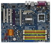
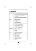
about the model you are using. www.asrock.com/support/index.asp 1.1 Package Contents ASRock 4Core1600Twins-P35 Motherboard (ATX Form Factor: 12.0-in x 9.6-in, 30.5 cm x 24.4 cm) ASRock 4Core1600Twins-P35 Quick Installation Guide ASRock 4Core1600Twins-P35 Support CD One 80-conductor Ultra ATA 66/100 - ASRock 4Core1600Twins-P35 | User Manual - Page 6
-Threading Technology (see CAUTION 2) - Supports Untied Overclocking Technology (see CAUTION 3) - Supports EM64T CPU - Northbridge: Intel® P35/G33 - Southbridge: Intel® ICH9 - Dual Channel DDR3/DDR2 Memory Technology (see CAUTION 4) - 2 x DDR3 DIMM slots (green) - Support DDR3 1333/1066/800 non-ECC - ASRock 4Core1600Twins-P35 | User Manual - Page 7
- 4Mb AMI BIOS - AMI Legal BIOS - Supports "Plug and Play" - ACPI 1.1 Compliance Wake Up Events - Supports jumperfree - AMBIOS 2.3.1 Support - CPU, DRAM, NB, SB, VTT Voltage Multi-adjustment - Supports I. O. T. (Intelligent Overclocking Technology) Support CD - Drivers, Utilities, AntiVirus - ASRock 4Core1600Twins-P35 | User Manual - Page 8
guide of memory modules on page 17 for proper installation. 5. Please check the table below for the CPU FSB frequency and its corresponding memory support frequency. CPU FSB Frequency Memory Support Frequency 1600 DDR2 800, DDR2 1066, DDR3 1066, DDR3 1333 1333 DDR2 667, DDR2 800, DDR2 - ASRock 4Core1600Twins-P35 | User Manual - Page 9
may be less than 4GB for the reservation for system usage under Windows® XP and Windows® VistaTM. For Windows® XP 64-bit and Windows® VistaTM 64-bit with 64-bit CPU, there is no such limitation. 7. For microphone input, this motherboard supports both stereo and mono modes. For audio output, this - ASRock 4Core1600Twins-P35 | User Manual - Page 10
and users who purchase this motherboard and plan to submit Windows® VistaTM Premium 2008 and Basic logo, please follow below table for minimum hardware requirements. CPU Memory VGA Celeron 420 1GB system memory (Premium) 512MB Single Channel (Basic) DX10 with WDDM Driver with 128bit VGA memory - ASRock 4Core1600Twins-P35 | User Manual - Page 11
: MIC IN LAN PHY Super I/O AUDIO CODEC PCIE1 RAID FSB2 1 1 FSB3 FSB1 1 AGI_EXPRESS1 PCI1 PCI EXPRESS 4Mb BIOS PCI2 1 WIFI PCI3 CD1 HD_AUDIO1 HDMI_SPDIF1 1 1 FLOPPY1 IR1 1 4Core1600Twins-P35 FSB1600 Dual Channel Quad Core CPU IDE1 1 CLRCMOS1 CMOS Battery Intel ICH9 SATAII CHA_FAN1 - ASRock 4Core1600Twins-P35 | User Manual - Page 12
1 . 5 ASRock 8CH_eSATAII I/O Plus 1 2 3 4 7 5 8 6 9 14 13 12 11 10 1 PS/2 Mouse Port (Green) 2 Parallel Port 3 RJ-45 Port 4 Side Speaker (Gray) 5 Rear Speaker (Black) 6 Central / Bass (Orange) 7 - ASRock 4Core1600Twins-P35 | User Manual - Page 13
Precautions Take note of the following precautions before you install motherboard components or change any motherboard settings. 1. Unplug the power cord from the wall socket before touching any component. 2. To avoid damaging the motherboard components due to static electricity, NEVER place your - ASRock 4Core1600Twins-P35 | User Manual - Page 14
the installation of Intel 775-LAND CPU, please follow the steps below. 775-Pin Socket Overview Before you insert the 775-LAND CPU into the socket, please check if the CPU surface is unclean or if there is any bent pin on the socket. Do not force to insert the CPU into the socket if above situation - ASRock 4Core1600Twins-P35 | User Manual - Page 15
to use the cap tab to handle and avoid kicking off the PnP cap. 2. This cap must be placed if returning the motherboard for after service. Step 4. Close the socket: Step 4-1. Rotate the load plate onto the IHS. Step 4-2. While pressing down lightly on load plate, engage the load lever. Step - ASRock 4Core1600Twins-P35 | User Manual - Page 16
Heatsink This motherboard is equipped with 775-Pin socket that supports Intel 775-LAND CPU. Please adopt the type of heatsink and cooling fan compliant with Intel 775-LAND CPU to dissipate heat. Before you installed the heatsink, you need to spray thermal interface material between the CPU and the - ASRock 4Core1600Twins-P35 | User Manual - Page 17
2.5 Installation of Memory Modules (DIMM) This motherboard provides four 240-pin DDR2 (Double Data Rate 2) DIMM slots and two 240-pin DDR3 (Double Data Rate 3) DIMM slots, and supports Dual Channel Memory Technology. For dual channel configuration, you always need to install identical (the same - ASRock 4Core1600Twins-P35 | User Manual - Page 18
), or in the set of orange slots (DDRII_2 and DDRII_4). 2. If only one memory module or three memory modules are installed in the DDR2 DIMM slots on this motherboard, it is unable to activate the Dual Channel Memory Technology. If only one memory module is installed in the DDR3 DIMM slots on this - ASRock 4Core1600Twins-P35 | User Manual - Page 19
matches the break on the slot. notch break notch break The DIMM only fits in one correct orientation. It will cause permanent damage to the motherboard and the DIMM if you force the DIMM into the slot at incorrect orientation. Step 3. Firmly insert the DIMM into the slot until the retaining - ASRock 4Core1600Twins-P35 | User Manual - Page 20
of the expansion card and make necessary hardware settings for the card before you start the installation. Operation Guide This motherboard supports CrossFireTM feature supported with Windows® XP with Service Pack 2 and VistaTM OS. Please check AMD website for ATITM CrossFireTM driver updates - ASRock 4Core1600Twins-P35 | User Manual - Page 21
will release in the future, please refer to ATITM graphics card manuals for detailed installation guide. Step 1. Connect to the system power supply. Please connect a hard disk power connector to SLI/XFIRE Power connector on this motherboard. It is recommended to use 500-Watt power supply or greater - ASRock 4Core1600Twins-P35 | User Manual - Page 22
Interconnects on the top of Radeon graphics cards. (CrossFireTM Bridge is provided with the graphics card you purchase, not bundled with this motherboard. Please refer to your graphics card vendor for details.) CrossFireTM Bridge Step 5. Connect the DVI monitor cable to the DVI connector on - ASRock 4Core1600Twins-P35 | User Manual - Page 23
to installation. Please check AMD website for ATITM driver updates. Step 8. Install the required drivers to your system. For Windows® XP OS: A. ATITM recommends Windows® XP Service Pack 2 or higher to be installed (If you have Windows® XP Service Pack 2 or higher installed in your system, there - ASRock 4Core1600Twins-P35 | User Manual - Page 24
please check AMD website for updates and details. 2.8 Surround Display Feature This motherboard supports Surround Display upgrade. With the external add-on PCI Express VGA card, you can easily enjoy the benefits of Surround Display feature. For the detailed instruction, please refer to the document - ASRock 4Core1600Twins-P35 | User Manual - Page 25
and pin2 are "Short" when jumper cap is placed on these 2 pins. Jumper Setting Description PS2_USB_PWR1 (see p.11 No. 1) 1_2 +5V 2_3 +5VSB Short pin2, clear the CMOS right after you update the BIOS. If you need to clear the CMOS when you just finish updating the BIOS, you must boot up the - ASRock 4Core1600Twins-P35 | User Manual - Page 26
and memory module may not work properly on this motherboard. Please refer to below jumper settings. 4_5 FSB2 FSB3 1_2 1_2 FSB1 FSB1333 / DDR2 1066 Note3: If you use a FSB1066-CPU and adopt a DDR2 1066 memory module on this motherboard, you need to adjust the jumpers. Please short pin2, pin3 for - ASRock 4Core1600Twins-P35 | User Manual - Page 27
to the motherboard connect the black end to the IDE devices 80-conductor ATA 66/100/133 cable Note: Please refer to the instruction of your (Port5) SATAII_2 (Port1) These four Serial ATAII (SATAII) connectors support SATA data cables for internal storage devices. The current SATAII interface - ASRock 4Core1600Twins-P35 | User Manual - Page 28
cable can be connected to the SATA / SATAII hard disk or the SATAII connector on this motherboard. You can also use the SATA data cable to connect SATAII_6 (Port5) connector and eSATAII panel, there are three USB 2.0 headers on this motherboard. Each USB 2.0 header can support two USB 2.0 ports. 28 - ASRock 4Core1600Twins-P35 | User Manual - Page 29
header supports WiFi+AP function with ASRock WiFi supports Jack Sensing, but the panel wire on the chassis must support HDA to function correctly. Please follow the instruction in our manual and chassis manual BIOS Setup Utility. Enter Advanced Settings, and then select Chipset Configuration. Set the - ASRock 4Core1600Twins-P35 | User Manual - Page 30
fan (Quiet Fan) support, the 3-Pin CPU fan still can work successfully even without the fan speed control function. If you plan to connect the 3-Pin CPU fan to the CPU fan connector on this motherboard, please connect it to Pin 1-3. Pin 1-3 Connected 3-Pin Fan Installation ATX Power Connector (24 - ASRock 4Core1600Twins-P35 | User Manual - Page 31
Though this motherboard provides 24-pin ATX power connector, 12 24 it can still work if you adopt a traditional 20-pin ATX power supply. To use the 20-pin ATX power supply, please plug your power supply along with Pin 1 and Pin 13. 20-Pin ATX Power Supply Installation 1 13 ATX 12V Power - ASRock 4Core1600Twins-P35 | User Manual - Page 32
Guide HDMI (High-Definition Multi-media Interface) is an all-digital audio/video specification, which provides an interface between any compatible digital audio/ video source, such as a set manual of HDMI VGA card vendor. Incorrect connection may cause permanent damage to this motherboard motherboard - ASRock 4Core1600Twins-P35 | User Manual - Page 33
Interface Introduction What is eSATAII? This motherboard supports eSATAII interface, the external SATAII specification. and in working condition. 2. If you set "Configure SATAII as" option in BIOS setup to IDE mode, Hot Plug function is not supported with eSATAII devices. If you still want to - ASRock 4Core1600Twins-P35 | User Manual - Page 34
1. In order to enable the eSATAII port of the I/O shield, you need to connect the orange SATAII connector (SATAII_6 (Port5); see p.11 No.17) and the eSATAII connector (eSATAII; see p.11 No.36) with a SATA data cable first. Connect the SATA data cable to the orange SATAII connector (SATAII_6 (Port5 - ASRock 4Core1600Twins-P35 | User Manual - Page 35
Comparison between eSATAII and other devices IEEE 1394 USB 2.0 SATA eSATAII/SATAII 400Mb/s 480Mb/s 1.5Gb/s (1500Mb/s) 3.0Gb/s (3000Mb/s) 35 - ASRock 4Core1600Twins-P35 | User Manual - Page 36
guide. Some default setting of SATAII hard disks may not be at SATAII mode, which operate with the best performance. In order to enable SATAII function, please follow the below instruction 's website for details: http://www.hitachigst.com/hdd/support/download.htm The above examples are just for your - ASRock 4Core1600Twins-P35 | User Manual - Page 37
motherboard adopts Intel® ICH9 south bridge chipset that supports Serial ATA (SATA) / Serial ATAII (SATAII) hard disks. You may install SATA / SATAII hard disks on this motherboard for internal storage devices. This section will guide / SATAII HDDs are NOT set for RAID configuration, it is called " - ASRock 4Core1600Twins-P35 | User Manual - Page 38
is installed into system properly. The latest SATA / SATAII driver is available on our support website: www.asrock.com 4. Make sure to use the SATA power cable & data cable, which are from our motherboard package. 5. Please follow below instructions step by step to reduce the risk of HDD crash or - ASRock 4Core1600Twins-P35 | User Manual - Page 39
cable to (White) to the power supply 1x4-pin cable. the motherboard's SATAII connector. SATA power cable 1x4-pin power connector (White) Step attention, before you process the Hot Unplug: Please do follow below instruction sequence to process the Hot Unplug, improper procedure will cause the SATA - ASRock 4Core1600Twins-P35 | User Manual - Page 40
is not provided by the chipset vendor, AHCI function is not supported under Windows® 2000. 2. The AHCI driver in our support CD is non-logo. 2.18.1 Installing Windows® 2000 / XP / XP 64-bit Without RAID Functions If you want to install Windows® 2000 / XP / XP 64-bit OS on your SATA / SATAII HDDs - ASRock 4Core1600Twins-P35 | User Manual - Page 41
drive to boot your system, and follow the instruction to install Windows® VistaTM / VistaTM 64-bit OS on your system. When you see "Where do you want to install Windows?" page, please insert the ASRock Support CD into your optical drive, and click the "Load Driver" button on the left on the bottom - ASRock 4Core1600Twins-P35 | User Manual - Page 42
64-bit OS on your system. After setting up BIOS, you can start to install Windows® VistaTM / VistaTM 64-bit on your system. 2 . 1 9 Untied Overclocking Technology This motherboard supports Untied Overclocking Technology, which means during overclocking, FSB enjoys better margin due to fixed PCI - ASRock 4Core1600Twins-P35 | User Manual - Page 43
SETUP UTILITY to configure your system. The BIOS FWH chip on the motherboard stores the BIOS SETUP UTILITY. You may run the BIOS SETUP UTILITY when you start up the computer. Please press during the Power-On-Self-Test (POST) to enter the BIOS SETUP UTILITY, otherwise, POST will continue with - ASRock 4Core1600Twins-P35 | User Manual - Page 44
Screen To load optimal default values for all the settings To save changes and exit the BIOS SETUP UTILITY To jump to the Exit Screen ] BIOS Version : 4Core1600Twins-P35 P1.00 Processor Type : Intel (R) Core(TM)2 Extreme CPU X9770 @ 3.20GHz (64bit) Processor Speed : 3200MHz Microcode Update : - ASRock 4Core1600Twins-P35 | User Manual - Page 45
Configuration, SuperIO Configuration, and USB Configuration. BIOS SETUP UTILITY Main Advanced H/W Monitor Boot Security Exit Advanced Settings WARNING : Setting wrong values in below sections may cause system to malfunction. CPU Configuration Chipset Configuration ACPI Configuration IDE - ASRock 4Core1600Twins-P35 | User Manual - Page 46
BIOS SETUP UTILITY Advanced CPU Configuration Overclock Mode CPU Frequency (MHz) PCIE Frequency (MHz) Boot Failure Guard Spread Spectrum [Auto] [400] [100] [Enabled] [Auto] Ratio Status Unlocked (Min:06, Max:Unlimited) Ratio Actual Value 8 Enhanced Halt State Intel Virtualization tech. CPU - ASRock 4Core1600Twins-P35 | User Manual - Page 47
Schemes" as "Portable/Laptop" to enable this function. If you install Windows® VistaTM and want to enable this function, please set this item to [Enabled]. This item will be hidden if the current CPU does not support Intel (R) SpeedStep(tm) tech.. Please note that enabling this function may reduce - ASRock 4Core1600Twins-P35 | User Manual - Page 48
DDR2 memory modules, or select [400MHz (DDR3 800)], [533MHz (DDR3 1066)] or [667MHz (DDR3 1333)] for DDR3 memory modules. The configuration options depend on the CPU and memory module you adopt on this motherboard. Please refer to page 8 for the CPU FSB frequency and its corresponding memory support - ASRock 4Core1600Twins-P35 | User Manual - Page 49
CPU Voltage. Configuration options: [Auto] and [Manual]. The default value of this feature is [Auto]. DRAM Voltage Use this to select DRAM Voltage. Configuration options for DDR2 DRAM RCOMP Setting Use this to adjust DRAM RCOMP Setting feature. Configuration options: [Auto] and [Manual]. The default - ASRock 4Core1600Twins-P35 | User Manual - Page 50
3.3.3 ACPI Configuration BIOS SETUP UTILITY Advanced ACPI Configuration Suspend To RAM Repost Video on STR Resume Suspend to RAM Use this item to select whether to auto-detect or disable the Suspend-toRAM feature. Select [Auto] will enable this feature if the OS supports it. If you set this item - ASRock 4Core1600Twins-P35 | User Manual - Page 51
set this option to [Enabled] if you plan to use this motherboard to submit Windows® VistaTM certification. 3.3.4IDE Configuration BIOS under Windows environment if this option is enabled. Configuration options: [Enabled] and [Disabled]. AHCI (Advanced Host Controller Interface) supports NCQ - ASRock 4Core1600Twins-P35 | User Manual - Page 52
set the IDE configuration for the device that you specify. We will use the "Primary IDE Master" as the example in the following instruction. BIOS .0 GB :Supported :16Sectors :4 :MultiWord DMA-2 :Ultra DMA-5 :Supported [Auto] hard disk > 512 MB under DOS and Windows; for Netware and UNIX user, select - ASRock 4Core1600Twins-P35 | User Manual - Page 53
Data Transfer Use this item to enable 32-bit access to maximize the IDE hard disk data transfer rate. 3.3.5PCIPnP Configuration BIOS SETUP UTILITY Advanced Advanced PCI / PnP Settings PCI Latency Timer PCI IDE BusMaster [32] [Enabled] Value in units of PCI clocks for PCI device latency timer - ASRock 4Core1600Twins-P35 | User Manual - Page 54
[378] [ECP + EPP] [1.9] [DMA3] [IRQ7] Allow BIOS to Enable or Disable Floppy Controller. +F1 F9 F10 ESC Select set the address for the onboard infrared port or disable it. Configuration options: [Disabled], [2F8 / IRQ3], and [2E8 / IRQ3]. If you plan to use ASRock DeskExpress on this motherboard - ASRock 4Core1600Twins-P35 | User Manual - Page 55
or disable it. Configuration options: [Disabled], [378], and [278]. Parallel Port Mode Use this item to set the operation mode of the parallel port. The default value is [ECP+EPP]. If this option is set to [ECP+EPP], it will show the EPP version in the following item, "EPP Version". Configuration - ASRock 4Core1600Twins-P35 | User Manual - Page 56
controller. USB 2.0 Support Use this item to enable or disable the USB 2.0 support. Legacy USB Support Use this item to enable or disable the support to emulate legacy of the CPU temperature, motherboard temperature, CPU fan speed, chassis fan speed, and the critical voltage. BIOS SETUP UTILITY - ASRock 4Core1600Twins-P35 | User Manual - Page 57
the available devices on your system for you to configure the boot settings and the boot priority. Main Advanced BIOS SETUP UTILITY H/W Monitor Boot Security Exit Boot Settings Boot Settings Configuration Configure Settings during System Boot. 1st Boot Device 2nd Boot Device 3rd Boot Device - ASRock 4Core1600Twins-P35 | User Manual - Page 58
the supervisor/user password for the system. For the user password, you may also clear it. BIOS SETUP UTILITY Main Advanced H/W Monitor Boot Security Exit Security Settings Supervisor Password : Not Installed User Password : Not Installed Change Supervisor Password Change User Password - ASRock 4Core1600Twins-P35 | User Manual - Page 59
and exit setup?" Select [OK] to save the changes and exit the BIOS SETUP UTILITY. Discard Changes and Exit When you select this option, it message, "Discard changes and exit setup?" Select [OK] to exit the BIOS SETUP UTILITY without saving any changes. Discard Changes When you select this option - ASRock 4Core1600Twins-P35 | User Manual - Page 60
install the necessary drivers to activate the devices. 4.2.3 Utilities Menu The Utilities Menu shows the applications software that the motherboard supports. Click on a specific item then follow the installation wizard to install it. 4.2.4 Contact Information If you need to contact ASRock or want to
-
 1
1 -
 2
2 -
 3
3 -
 4
4 -
 5
5 -
 6
6 -
 7
7 -
8
-
9
-
10
-
11
-
12
-
13
-
14
-
15
-
16
-
17
-
18
-
19
-
20
-
21
-
22
-
23
-
24
-
25
-
26
-
27
-
28
-
29
-
30
-
31
-
32
-
33
-
34
-
35
-
36
-
37
-
38
-
39
-
40
-
41
-
42
-
43
-
44
-
45
-
46
-
47
-
48
-
49
-
50
-
51
-
52
-
53
-
54
-
55
-
56
-
57
-
58
-
59
-
60
 |
 |

1
4Core1600Twins-P35
User Manual
Version 1.0
Published December 2007
Copyright©2007 ASRock INC. All rights reserved.