ASRock 4CoreDX90-VSTA R2.0 User Manual
ASRock 4CoreDX90-VSTA R2.0 Manual
 |
View all ASRock 4CoreDX90-VSTA R2.0 manuals
Add to My Manuals
Save this manual to your list of manuals |
ASRock 4CoreDX90-VSTA R2.0 manual content summary:
- ASRock 4CoreDX90-VSTA R2.0 | User Manual - Page 1
4CoreDX90-VSTA User Manual Version 2.0 Published April 2007 Copyright©2007 ASRock INC. All rights reserved. 1 - ASRock 4CoreDX90-VSTA R2.0 | User Manual - Page 2
any form or by any means, except duplication of documentation by the purchaser for backup purpose, without written consent of ASRock Inc. Products and corporate names appearing in this manual may or may not be registered trademarks or copyrights of their respective companies, and are used only for - ASRock 4CoreDX90-VSTA R2.0 | User Manual - Page 3
Windows® VistaTM Basic Logo 9 1.4 Motherboard Layout 10 1.5 ASRock 8CH I/O Plus Panel 11 2. Installation 12 2.1 Screw HDDs ..... 23 2.11 SATA HDD Hot Plug Feature and Operation Guide ....... 24 2.12 Driver Installation Guide 26 2.13 HDMR Card and Driver Installation 26 2.14 Installing Windows - ASRock 4CoreDX90-VSTA R2.0 | User Manual - Page 4
3.5 Boot Screen 45 3.5.1 Boot Settings Configuration 46 3.6 Security Screen 46 3.7 Exit Screen 47 4. Software Support 48 4.1 Install Operating System 48 4.2 Support CD Information 48 4.2.1 Running Support CD 48 4.2.2 Drivers Menu 48 4.2.3 Utilities Menu 48 4.2.4 Contact Information 48 4 - ASRock 4CoreDX90-VSTA R2.0 | User Manual - Page 5
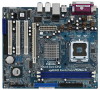
VGA cards and CPU support lists on ASRock website as well. ASRock website http://www.asrock.com 1.1 Package Contents ASRock 4CoreDX90-VSTA Motherboard (Micro ATX Form Factor: 9.6-in x 8.2-in, 24.4 cm x 20.8 cm) ASRock 4CoreDX90-VSTA Quick Installation Guide ASRock 4CoreDX90-VSTA Support CD One 80 - ASRock 4CoreDX90-VSTA R2.0 | User Manual - Page 6
LGA 775 for Intel® CoreTM 2 Extreme / CoreTM 2 Duo / Pentium® XE / Pentium® D / Pentium® Dual Core / Pentium® 4 / Celeron® / Celeron® D, supporting (ALC883 Audio Codec) - VIA® PHY VT6103 - Speed: 10/100 Ethernet - Supports Wake-On-LAN ASRock 8CH I/O Plus - 1 x PS/2 Mouse Port - 1 x PS/2 Keyboard - ASRock 4CoreDX90-VSTA R2.0 | User Manual - Page 7
4 USB 2.0 ports) (see CAUTION 6) - 4Mb AMI BIOS - AMI Legal BIOS - Supports "Plug and Play" - ACPI 1.1 Compliance Wake Up Events - Supports jumperfree - SMBIOS 2.3.1 Support - Drivers, Utilities, AntiVirus Software (Trial Version) - CPU Temperature Sensing - Chassis Temperature Sensing - CPU Fan - ASRock 4CoreDX90-VSTA R2.0 | User Manual - Page 8
install the PC system. 5. For microphone input, this motherboard supports both stereo and mono modes. For audio output, this motherboard supports 2-channel, 4-channel, 6-channel, and 8-channel modes. Please ® Windows® VistaTM / VistaTM 64-bit driver and related information. ASRock website http://www - ASRock 4CoreDX90-VSTA R2.0 | User Manual - Page 9
1.3 Minimum Hardware Requirement Table for Windows® VistaTM Basic Logo For system integrators and users who purchase our motherboard and plan to submit Windows® VistaTM Basic logo, please follow below table for minimum hardware requirement. CPU Memory VGA Celeron D 326 512MB Single Channel* DX9.0 - ASRock 4CoreDX90-VSTA R2.0 | User Manual - Page 10
PHY 4Mb BIOS Audio CODEC CD1 1 HD_AUDIO1 7.1 CH HD PCIE1 PCI1 4CoreDX90-VSTA PCI2 USB2.0 PCI3 HDMR1 USB4_5 1 USB6_7 1 VIA VT8237A FLOPPY1 CMOS CMOS Jumper (CLRCMOS1) 5 North Bridge Controller 18 Floppy Connector (FLOPPY1) 6 775-Pin CPU Socket 19 HDMR Slot (HDMR1) 7 2 x 184-pin DDR - ASRock 4CoreDX90-VSTA R2.0 | User Manual - Page 11
1.5 ASRock 8CH I/O Plus 1 2 3 4 5 8 6 9 7 10 14 13 12 11 1 PS/2 Mouse Port (Green) 2 Parallel Port 3 USB 2.0 Ports (USB23) 4 RJ-45 Port 5 Side Speaker (Gray) 6 Rear Speaker (Black) 7 - ASRock 4CoreDX90-VSTA R2.0 | User Manual - Page 12
Chapter 2 Installation 4CoreDX90-VSTA is a Micro ATX form factor (9.6" x 8.2", 24.4 x 20.8 cm) motherboard. Before you install the motherboard, study the configuration of your chassis to ensure that the motherboard - ASRock 4CoreDX90-VSTA R2.0 | User Manual - Page 13
to fully open position at approximately 135 degrees. Step 1-3. Rotate the load plate to fully open position at approximately 100 degrees. Step 2. Insert the 775-LAND CPU: Step 2-1. Hold the CPU by the edges where are marked with black lines. Step 2-2. Orient the CPU with IHS (Integrated Heat Sink - ASRock 4CoreDX90-VSTA R2.0 | User Manual - Page 14
Pick and Place Cap): Use your left hand index finger and thumb to support the load plate edge, engage PnP cap with right hand thumb and peel the PnP cap. 2. This cap must be placed if returning the motherboard for after service. Step 4. Close the socket: Step 4-1. Rotate the load plate onto the IHS. - ASRock 4CoreDX90-VSTA R2.0 | User Manual - Page 15
equipped with 775-Pin socket that supports Intel 775-LAND CPU. Please adopt the type of heatsink and cooling fan compliant with Intel 775-LAND refer to the instruction manuals of your CPU fan and heatsink. Below is an example to illustrate the installation of the heatsink for 775-LAND CPU. Step - ASRock 4CoreDX90-VSTA R2.0 | User Manual - Page 16
2.5 Installation of Memory Modules (DIMM) This motherboard is equipped with two 184-pin DDR (Double Data Rate) DIMM slots. Please make sure to disconnect power supply before adding or removing DIMMs or the system components. Step 1. Step 2. Unlock a DIMM slot by pressing the retaining clips - ASRock 4CoreDX90-VSTA R2.0 | User Manual - Page 17
2.6 Expansion Slots (PCI, HDMR and PCI Express Slots) There are 3 PCI slots, 1 HDMR slot and 1 PCI Express slot on this motherboard. PCI slots: PCI slots are used to install expansion cards that have the 32-bit PCI interface. HDMR slot: HDMR slot is used to insert a HDMR card with v.92 Modem - ASRock 4CoreDX90-VSTA R2.0 | User Manual - Page 18
2.7 Jumpers Setup The illustration shows how jumpers are setup. When the jumper cap is placed on pins, the jumper is "Short". If no jumper cap is placed on pins, the jumper is "Open". The illustration shows a 3-pin jumper whose pin1 and pin2 are "Short" when jumper cap is placed on these 2 pins. - ASRock 4CoreDX90-VSTA R2.0 | User Manual - Page 19
please set the IDE device as "Master". Please refer to the instruction of your IDE device vendor for the details. Besides, to optimize see p.10, No. 12) SATA2 SATA1 These two Serial ATA (SATA) connectors support SATA data cables for internal storage devices. The current SATA interface allows up to - ASRock 4CoreDX90-VSTA R2.0 | User Manual - Page 20
panel audio cable that allows convenient connection and control of audio devices. 1. High Definition Audio supports Jack Sensing, but the panel wire on the chassis must support HDA to function correctly. Please follow the instruction in our manual and chassis manual to install your system. 20 - ASRock 4CoreDX90-VSTA R2.0 | User Manual - Page 21
the CPU fan cable to this connector and match the black wire to the ground pin. Though this motherboard provides 4-Pin CPU fan (Quiet Fan) support, the 3-Pin CPU fan still can work successfully even without the fan speed control function. If you plan to connect the 3-Pin CPU fan to - ASRock 4CoreDX90-VSTA R2.0 | User Manual - Page 22
ATX Power Connector (20-pin ATXPWR1) (see p.10, No. 3) ATX 12V Connector (4-pin ATX12V1) (see p.10, No. 2) Please connect an ATX power supply to this connector. Please note that it is necessary to connect a power supply with ATX 12V plug to this connector so that it can provides sufficient power. - ASRock 4CoreDX90-VSTA R2.0 | User Manual - Page 23
supports Serial ATA (SATA) hard disks and RAID (RAID 0, RAID 1 and JBOD) functions. You may install SATA hard disks on this motherboard for internal storage devices. This section will guide and Hot Swap Functions for SATA HDDs 4CoreDX90-VSTA motherboard supports Hot Plug and Hot Swap functions for - ASRock 4CoreDX90-VSTA R2.0 | User Manual - Page 24
is installed into system properly. The latest SATA driver is available on our support website: www.asrock.com 4. Make sure to use the SATA power cable & data cable, which are from our motherboard package. 5. Please follow below instructions step by step to reduce the risk of HDD crash or data loss - ASRock 4CoreDX90-VSTA R2.0 | User Manual - Page 25
data cable to the SATA HDD. How to Hot Unplug a SATA HDD: Points of attention, before you process the Hot Unplug: Please do follow below instruction sequence to process the Hot Unplug, improper procedure will cause the SATA HDD damage and data loss. Step 1 Unplug SATA data cable from SATA HDD - ASRock 4CoreDX90-VSTA R2.0 | User Manual - Page 26
2.12 Driver Installation Guide To install the drivers to your system, please insert the support CD to your optical drive first. Then, the drivers compatible to your system can be auto-detected and listed on the support CD driver page. Please follow the order from up to bottom side to install those - ASRock 4CoreDX90-VSTA R2.0 | User Manual - Page 27
STEP 2: Make a SATA Driver Diskette. A. Insert the ASRock Support CD into your optical drive to boot your system. B. guide in the Support CD for proper configuration. Please refer to the BIOS RAID installation guide of the document in the following path in the Support CD: .. \ RAID Installation Guide - ASRock 4CoreDX90-VSTA R2.0 | User Manual - Page 28
RAID installation guide part of the document in the following path in the Support CD: .. \ RAID Installation Guide 2. If instruction to install Windows® VistaTM / Windows® VistaTM 64-bit OS on your system. When you see "Where do you want to install Windows?" page, please insert the ASRock Support - ASRock 4CoreDX90-VSTA R2.0 | User Manual - Page 29
Windows® XP / Windows® XP 64-bit / Windows® VistaTM / Windows® VistaTM 64-bit OS on your system. 2.16 Untied Overclocking Technology This motherboard supports Untied Overclocking Technology, which means during overclocking, FSB enjoys better margin due to fixed PCI / PCIE bus. You may set "CPU Host - ASRock 4CoreDX90-VSTA R2.0 | User Manual - Page 30
3. BIOS SETUP UTILITY 3.1 Introduction This section explains how to use the BIOS SETUP UTILITY to configure your system. The Flash Memory on the motherboard stores the BIOS SETUP UTILITY. You may run the BIOS SETUP UTILITY when you start up the computer. Please press during the Power-On-Self- - ASRock 4CoreDX90-VSTA R2.0 | User Manual - Page 31
Exit System Overview System Time System Date [17:00:09] [Mon 04/30/2007] BIOS Version : 4CoreDX90-VSTA BIOS P1.20 Processor Type : Intel (R) CPU 3.40 GHz (64bit supported) Processor Speed : 3400MHz Microcode Update : F65/7 Cache Size : 4096KB Total Memory DRD 1 DDR 2 : 512MB with 64MB - ASRock 4CoreDX90-VSTA R2.0 | User Manual - Page 32
BIOS SETUP UTILITY Main Advanced H/W Monitor Boot Security Exit Advanced Settings WARNING : Setting wrong values in below sections may cause system to malfunction. CPU Configuration Chipset Configuration ACPI Configuration IDE Configuration PCIPnP Configuration Floppy Configuration SuperIO - ASRock 4CoreDX90-VSTA R2.0 | User Manual - Page 33
option " Intel (R) SpeedStep(tm) tech." in advance. Enhance Halt State All processors support the Halt State (C1). The C1 state is supported through the native processor instructions HLT and MWAIT and requires no hardware support from the chipset. In the C1 power state, the processor maintains the - ASRock 4CoreDX90-VSTA R2.0 | User Manual - Page 34
® VistaTM and want to enable this function, please set this item to [Enabled]. This item will be hidden if the current CPU does not support Intel (R) SpeedStep(tm) tech.. Please note that enabling this function may reduce CPU voltage and lead to system stability or compatibility issue with some - ASRock 4CoreDX90-VSTA R2.0 | User Manual - Page 35
3.3.2 Chipset Configuration BIOS SETUP UTILITY Advanced Chipset Settings DRAM Frequency Flexibility Option DRAM CAS# Latency DRAM Bank Interleave Precharge to Active (Trp) Active to Precharge (Tras) Active to CMD (Trcd) REF to ACT/REF to REF (Trfc) ACT (0) to ACT (1) (Trrd) Read to Precharge (Trtp - ASRock 4CoreDX90-VSTA R2.0 | User Manual - Page 36
REF to ACT / REF to REF (Trfc) Use this option to select REF to ACT / REF to REF (Trfc). Configuration options: [Auto], [8T] to [71T]. The default value is set to [Auto] to set the timing by dram SPD. ACT(0) to ACT (1) (Trrd) Use this option to select ACT(0) to ACT (1) (Trrd). Configuration options: - ASRock 4CoreDX90-VSTA R2.0 | User Manual - Page 37
V-Link Speed This allows you to set the North Bridge and South Bridge V-Link Speed of VIA chipset. configuration options: [Normal], [Fast]. The default value is [Normal]. PCI Delay Transaction Enable PCI Delay Transaction to allow other PCI masters to use the PCI BUS while the transaction is being - ASRock 4CoreDX90-VSTA R2.0 | User Manual - Page 38
field allows you to select whether to auto-detect or disable the Suspend-to-RAM feature. Select [Auto] will enable this feature if the system supports it. Restore on AC/Power Loss This allows you to set the power state after an unexpected AC/Power loss. If [Power Off] is selected - ASRock 4CoreDX90-VSTA R2.0 | User Manual - Page 39
will use the "Primary IDE Master" as the example in the following instruction, which can be applied to the configurations of "Primary IDE Slave", " Data Transfer :Hard Disk :ST340014A :40.0 GB :Supported :16Sectors :4 :MultiWord DMA-2 :Ultra DMA-5 :Supported [Auto] [Auto] [Auto] [Auto] [Auto] - ASRock 4CoreDX90-VSTA R2.0 | User Manual - Page 40
TYPE Use this item to configure the type of the IDE device that you specify. Configuration options: [Not Installed], [Auto], [CD/DVD], and [ARMD]. [Not Installed]: Select [Not Installed] to disable the use of IDE device. [Auto]: Select [Auto] to automatically detect the hard disk drive. After - ASRock 4CoreDX90-VSTA R2.0 | User Manual - Page 41
3.3.5 PCIPnP Configuration BIOS SETUP UTILITY Advanced Advanced PCI / PnP Settings PCI Latency Timer PCI IDE BusMaster [32] [Enabled] Value in units of PCI clocks for PCI device latency timer register. +F1 F9 F10 ESC Select Screen Select Item Change Option General Help Load Defaults Save and - ASRock 4CoreDX90-VSTA R2.0 | User Manual - Page 42
3.3.7 Super IO Configuration BIOS SETUP UTILITY Advanced Configure Super IO Chipset OnBoard Floppy Controller Serial Port Address Infrared Port Address Parallel Port Address Parallel Port Mode EPP Version ECP Mode DMA Channel Parallel Port IRQ [Enabled] [3F8 / IRQ4] [Disabled] [378] [ECP + EPP] - ASRock 4CoreDX90-VSTA R2.0 | User Manual - Page 43
Controller Use this item to enable or disable the use of USB controller. USB 2.0 Support Use this item to enable or disable the USB 2.0 support. Legacy USB Support Use this item to enable or disable the support to emulate legacy I/O devices such as mouse, keyboard,... etc. Or you may select [Auto - ASRock 4CoreDX90-VSTA R2.0 | User Manual - Page 44
3.4 Hardware Health Event Monitoring Screen In this section, it allows you to monitor the status of the hardware on your system, including the parameters of the CPU temperature, motherboard temperature, CPU fan speed, chassis fan speed, and the critical voltage. BIOS SETUP UTILITY Main Advanced - ASRock 4CoreDX90-VSTA R2.0 | User Manual - Page 45
3.5 Boot Screen In this section, it will display the available devices on your system for you to configure the boot settings and the boot priority. Main Advanced BIOS SETUP UTILITY H/W Monitor Boot Security Exit Boot Settings Boot Settings Configuration 1st Boot Device 2nd Boot Device 3rd - ASRock 4CoreDX90-VSTA R2.0 | User Manual - Page 46
3.5.1 Boot Settings Configuration BIOS SETUP UTILITY Boot Boot Settings Configuration Boot From Onboard LAN VIA SATA Raid Utility Bootup Num-Lock [Disabled] [Enabled] [On] To enable or disable the boot from onboard LAN feature. +F1 F9 F10 ESC Select Screen Select Item Change Option General - ASRock 4CoreDX90-VSTA R2.0 | User Manual - Page 47
3.7 Exit Screen Main BIOS SETUP UTILITY Advanced H/W Monitro Boot Security Exit Exit Options Save Changes and Exit Discard Changes and Exit Discard Changes Load Optimal Defaults Exit system setup after saving the changes. F10 key can be used for this operation. Select Screen Select Item - ASRock 4CoreDX90-VSTA R2.0 | User Manual - Page 48
applications software that the motherboard supports. Click on a specific item then follow the installation wizard to install it. 4.2.4 Contact Information If you need to contact ASRock or want to know more about ASRock, welcome to visit ASRock's website at http://www.asrock.com; or you may contact
-
 1
1 -
 2
2 -
 3
3 -
 4
4 -
 5
5 -
 6
6 -
 7
7 -
8
-
9
-
10
-
11
-
12
-
13
-
14
-
15
-
16
-
17
-
18
-
19
-
20
-
21
-
22
-
23
-
24
-
25
-
26
-
27
-
28
-
29
-
30
-
31
-
32
-
33
-
34
-
35
-
36
-
37
-
38
-
39
-
40
-
41
-
42
-
43
-
44
-
45
-
46
-
47
-
48
 |
 |
1
4CoreDX90-VSTA
User Manual
Version 2.0
Published April 2007
Copyright©2007 ASRock INC. All rights reserved.