ASRock 4CoreDual-SATA2 User Manual
ASRock 4CoreDual-SATA2 Manual
 |
View all ASRock 4CoreDual-SATA2 manuals
Add to My Manuals
Save this manual to your list of manuals |
ASRock 4CoreDual-SATA2 manual content summary:
- ASRock 4CoreDual-SATA2 | User Manual - Page 1
4CoreDual-SATA2 User Manual Version 1.1 Published September 2007 Copyright©2007 ASRock INC. All rights reserved. 1 - ASRock 4CoreDual-SATA2 | User Manual - Page 2
purchaser for backup purpose, without written consent of ASRock Inc. Products and corporate names appearing in this manual may or may not be registered trademarks or copyrights USA ONLY The Lithium battery adopted on this motherboard contains Perchlorate, a toxic substance controlled in Perchlorate - ASRock 4CoreDual-SATA2 | User Manual - Page 3
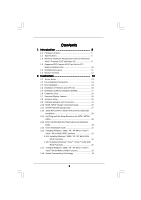
1.4 Supported PCI Express VGA Card List for PCI Express Graphics Slot 10 1.5 Motherboard Layout 11 1.6 HD 8CH I/O Panel 12 2. Installation 13 2.1 Screw Holes 13 2.2 Pre-installation Precautions 13 2.3 CPU Installation 14 2.4 Installation of Heatsink and CPU fan 16 2.5 Installation of Memory - ASRock 4CoreDual-SATA2 | User Manual - Page 4
34 3.1.1 BIOS Menu Bar 34 3.1.2 Navigation Keys 35 3.2 Main Screen 35 3.3 Advanced Screen 36 3.3.1 CPU Configuration 36 Exit Screen 50 4. Software Support 51 4.1 Install Operating System 51 4.2 Support CD Information 51 4.2.1 Running Support CD 51 4.2.2 Drivers Menu 51 4.2.3 Utilities - ASRock 4CoreDual-SATA2 | User Manual - Page 5
CPU support lists on ASRock website as well. ASRock website http://www.asrock.com 1.1 Package Contents ASRock 4CoreDual-SATA2 Motherboard (ATX Form Factor: 12.0-in x 9.6-in, 30.5 cm x 24.4 cm) ASRock 4CoreDual-SATA2 Quick Installation Guide ASRock 4CoreDual-SATA2 Support CD One 80-conductor Ultra - ASRock 4CoreDual-SATA2 | User Manual - Page 6
® / Celeron® D, supporting Quad Core Kentsfield processors (see CAUTION 1) - FSB 1066/800/533 MHz - Supports Hyper-Threading Technology (see CAUTION 2) - Supports Untied Overclocking Technology (see CAUTION 3) - Supports EM64T CPU - Northbridge: VIA® PT880 Pro/PT880 Ultra - Southbridge: VIA® VT8237S - ASRock 4CoreDual-SATA2 | User Manual - Page 7
- Front panel audio connector - 2 x USB 2.0 headers (support 4 USB 2.0 ports) (see CAUTION 11) - 4Mb AMI BIOS - AMI Legal BIOS - Supports "Plug and Play" - ACPI 1.1 Compliance Wake Up Events - Supports jumperfree - SMBIOS 2.3.1 Support - Drivers, Utilities, AntiVirus Software (Trial Version) - CPU - ASRock 4CoreDual-SATA2 | User Manual - Page 8
CAUTION! 1. When you adopt Quad Core CPU on this motherboard, FSB frequency may be reduced 5%. 2. About the setting of "Hyper Threading Technology", please check page 37. 3. This motherboard supports Untied Overclocking Technology. Please read "Untied Overclocking Technology" on page 33 for details. - ASRock 4CoreDual-SATA2 | User Manual - Page 9
Table for Windows® VistaTM Premium 2007 and Basic OS This motherboard can support all features in Windows® VistaTM Premium 2007. Please follow below table for minimum hardware requirement. CPU Memory VGA Celeron D 326 1GB system memory DX9.0 with WDDM Driver with 128bit VGA memory (Premium) with - ASRock 4CoreDual-SATA2 | User Manual - Page 10
8600 GTS GeForce 8800 GTS Radeon X1900XT RADEON X850XT RADEON X1300Pro RADEON X1600Pro RADEON X1600XT For the latest updates of the supported PCI Express VGA card list for PCI Express Graphics slot, please visit ASRock website for details. ASRock website: http://www.asrock.com/support/index.htm 10 - ASRock 4CoreDual-SATA2 | User Manual - Page 11
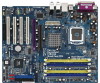
: LINE IN Center: FRONT Bottom: MIC IN CD1 IR1 1 Kentsfield FSB1066 Conroe VIA PT880 Pro / PT880 Ultra Chipset AGP 8X 1.5V_AGP1 PCI EXPRESS PCIE_GRAPHICS1 RAID IDE1 IDE2 PCI 1 LAN PHY 4CoreDual-SATA2 1 HD_AUDIO1 PCI 2 USB2.0 PCI 3 CMOS Battery CLRCMOS1 Audio CODEC HDMI_SPDIF1 GAME1 - ASRock 4CoreDual-SATA2 | User Manual - Page 12
7) (No. 4) (No. 5) 2 V -- -- 4 V V -- 6 V V V 8 V V V Side Speaker (No. 3) ---V * To enable Multi-Streaming function, you need to connect a front panel audio cable to the front panel audio header. After restarting your computer, you will find "Mixer" tool on your system. Please - ASRock 4CoreDual-SATA2 | User Manual - Page 13
4CoreDual-SATA2 is an ATX form factor (12.0" x 9.6", 30.5 x 24.4 cm) motherboard. Before you install the motherboard, study the configuration of your chassis to ensure that the motherboard fits into it. Make sure to unplug the power cord before installing or removing the motherboard. Failure - ASRock 4CoreDual-SATA2 | User Manual - Page 14
the installation of Intel 775-LAND CPU, please follow the steps below. 775-Pin Socket Overview Before you insert the 775-LAND CPU into the socket, please check if the CPU surface is unclean or if there is any bent pin on the socket. Do not force to insert the CPU into the socket if above situation - ASRock 4CoreDual-SATA2 | User Manual - Page 15
to use the cap tab to handle and avoid kicking off the PnP cap. 2. This cap must be placed if returning the motherboard for after service. Step 4. Close the socket: Step 4-1. Rotate the load plate onto the IHS. Step 4-2. While pressing down lightly on load plate, engage the load lever. Step - ASRock 4CoreDual-SATA2 | User Manual - Page 16
Heatsink This motherboard is equipped with 775-Pin socket that supports Intel 775-LAND CPU. Please adopt the type of heatsink and cooling fan compliant with Intel 775-LAND CPU to dissipate heat. Before you installed the heatsink, you need to spray thermal interface material between the CPU and the - ASRock 4CoreDual-SATA2 | User Manual - Page 17
2.5 Installation of Memory Modules (DIMM) 4CoreDual-SATA2 motherboard provides two 184-pin DDR (Double Data Rate) DIMM slots and two 240-pin DDRII DIMM slots, and supports Dual Channel Memory Technology. For dual channel configuration, you always need to install identical (the same brand, speed, - ASRock 4CoreDual-SATA2 | User Manual - Page 18
matches the break on the slot. notch break notch break The DIMM only fits in one correct orientation. It will cause permanent damage to the motherboard and the DIMM if you force the DIMM into the slot at incorrect orientation. Step 3. Firmly insert the DIMM into the slot until the retaining - ASRock 4CoreDual-SATA2 | User Manual - Page 19
is used to install a graphics card. The ASRock AGP slot has a special design of clasp that can securely fasten the inserted graphics card. AGP slot is used to install AGP expansion cards. Please do NOT use a 3.3V AGP card on the AGP slot of this motherboard! It may cause permanent damage! For the - ASRock 4CoreDual-SATA2 | User Manual - Page 20
Display Feature Thanks to ASRock patented PCI Express Graphics Technology, this motherboard supports Surround Display upgrade. With the external add-on AGP VGA card and PCI Express VGA card, you can easily enjoy the benefits of Surround Display feature. For the detailed instruction, please refer to - ASRock 4CoreDual-SATA2 | User Manual - Page 21
motherboard, please set the IDE device as "Master". Please refer to the instruction of your IDE device vendor for the details. Besides, to optimize compatibility and performance, please connect 12) (SATA2: see p.11, No. 11) SATA1 SATA2 These two Serial ATAII (SATAII) connectors support SATAII or - ASRock 4CoreDual-SATA2 | User Manual - Page 22
motherboard. Each USB 2.0 header can support two USB 2.0 ports. This header supports an optional wireless transmitting and receiving infrared module. This connector allows you to receive stereo audio input from sound sources such as a CD-ROM, DVD-ROM, TV tuner card, or MPEG card. Front Panel Audio - ASRock 4CoreDual-SATA2 | User Manual - Page 23
and OUT_RET are for HD audio panel only. You don't need to connect them for AC'97 audio panel. E. Enter BIOS Setup Utility. Enter Advanced Settings, and then select Chipset Configuration. Set the Front Panel Control option from [Auto] to [Enabled]. F. Enter Windows system. Click the icon on - ASRock 4CoreDual-SATA2 | User Manual - Page 24
Though this motherboard provides 4-Pin CPU fan (Quiet Fan) support, the 3-Pin CPU fan still can work successfully even without the fan speed control function. If you plan to connect the 3-Pin CPU fan to the CPU fan connector on this motherboard, please connect it to Pin 1-3. Pin 1-3 Connected 3-Pin - ASRock 4CoreDual-SATA2 | User Manual - Page 25
the black end (A) (Optional) C B A of HDMI_SPDIF cable to the HDMI_SPDIF header on the motherboard. Then connect the white end (B or C) of HDMI_SPDIF cable to the a HDMI_SPDIF connector of HDMI VGA card. A. black end +5V SPDIFOUT GND blue black B. white end (2-pin) - ASRock 4CoreDual-SATA2 | User Manual - Page 26
on this motherboard. For the proper installation of HDMI VGA card, please refer to the installation guide on page 19. Step 2. Connect the black end user manual of HDMI VGA card vendor. Incorrect connection may cause permanent damage to this motherboard and the HDMI VGA card. Step 3. Connect the - ASRock 4CoreDual-SATA2 | User Manual - Page 27
guide. Some default setting of SATAII hard disks may not be at SATAII mode, which operate with the best performance. In order to enable SATAII function, please follow the below instruction website for details: http://www.hitachigst.com/hdd/support/download.htm The above examples are just for your - ASRock 4CoreDual-SATA2 | User Manual - Page 28
VIA® VT8237S southbridge chipset that supports Serial ATA (SATA) / Serial ATAII (SATAII) hard disks and RAID (RAID 0, RAID 1, and JBOD) functions. You may install SATA / SATAII hard disks on this motherboard for internal storage devices. This section will guide 4CoreDual-SATA2 motherboard supports - ASRock 4CoreDual-SATA2 | User Manual - Page 29
(Black) connect to SATA / SATAII HDD 1x4-pin conventional power connector (White) connect to power supply driver is available on our support website: www.asrock.com 4. Make sure to use the SATA power cable & data cable, which are from our motherboard package. 5. Please follow below instructions - ASRock 4CoreDual-SATA2 | User Manual - Page 30
follow below instruction sequence to process the Hot Plug, improper procedure will cause the SATA / SATAII HDD damage and data loss. Step 1 Please connect SATA power cable 1x4-pin end Step 2 Connect SATA data cable to (White) to the power supply 1x4-pin cable. the motherboard's SATAII connector - ASRock 4CoreDual-SATA2 | User Manual - Page 31
it to our website. Please visit our website for RAID driver update in the near future. ASRock website: http://www.asrock.com 2.16.1 Installing Windows® 2000 / XP / XP 64-bit With RAID Functions If you want to install Windows® 2000, Windows® XP or Windows® XP 64-bit on your SATA / SATAII HDDs with - ASRock 4CoreDual-SATA2 | User Manual - Page 32
part of the document in the following path in the Support CD: .. \ RAID Installation Guide 2. If you want to use "VIA RAID Tool" in Windows® environment, please install SATA / SATAII drivers from the Support CD again so that "VIA RAID Tool" will be installed to your system as well. 2.16.2 Installing - ASRock 4CoreDual-SATA2 | User Manual - Page 33
64-bit OS on your system. 2.18 Untied Overclocking Technology This motherboard supports Untied Overclocking Technology, which means during overclocking, FSB enjoys better margin due to fixed AGP / PCI / PCIE bus. You may set "CPU Host Frequency" option of BIOS setup to [Auto], which will show you - ASRock 4CoreDual-SATA2 | User Manual - Page 34
the BIOS SETUP UTILITY to configure your system. The Flash Memory on the motherboard stores the BIOS SETUP UTILITY. You may run the BIOS SETUP off and then back on. Because the BIOS software is constantly being updated, the following BIOS setup screens and descriptions are for reference purpose - ASRock 4CoreDual-SATA2 | User Manual - Page 35
:00:09] [Thu 05/10/2007] BIOS Version : 4CoreDual-SATA2 BIOS P1.00 Processor Type : Intel (R) CPU 3.60 GHz (64bit) Processor Speed : 3600 MHz Microcode Update : F43/4 Cache Size : 1024KB Total Memory DDRII 1 DRD 1 DDRII 2 DDR 2 : 512MB Dual-Channel Memory Mode : None : 256MB/166MHz (DDR333 - ASRock 4CoreDual-SATA2 | User Manual - Page 36
CPU Configuration BIOS SETUP UTILITY Advanced CPU Configuration Overclock Mode CPU Frequency (MHz) PCIE Frequency (MHz) Spread Spectrum Boot Failure Guard Ratio Status Ratio Actual Value Max CPUID Value Limit Intel (R) Virtualization tech. No-Excute Memory Protection Hyper Threading Technology - ASRock 4CoreDual-SATA2 | User Manual - Page 37
malicious software to execute code. This option will be hidden if the current CPU does not support No-Excute Memory Protection. Hyper Threading Technology To enable this feature, it requires a computer system with an Intel Pentium®4 processor that supports Hyper-Threading technology and an operating - ASRock 4CoreDual-SATA2 | User Manual - Page 38
BIOS ] [Auto] [Auto] [Auto] [Auto] [Auto] [2T Command] DRAM Voltage AGP Voltage [Auto] [Auto] Options 133MHz 166MHz 200MHz Auto (DDR266) (DDR333) (DDR400) Frequency If [Auto] is selected, the motherboard will detect the memory module(s) inserted and assigns appropriate frequency automatically. - ASRock 4CoreDual-SATA2 | User Manual - Page 39
Channel] and [Dual Channel] if you have properly set the dual channel memory configuration. DRAM Command Rate Use this to select among [2T Command] Voltage. The default value is [Auto]. AGP Voltage Use this to select among [Auto], [Normal] and [High] for AGP Voltage. The default value is [Auto]. - ASRock 4CoreDual-SATA2 | User Manual - Page 40
on this motherboard, you may select [Auto], [8X] or [4X] as the AGP mode. If the installed AGP card is a 4X-AGP card, then you may set the AGP mode as [Auto], [4X], [2X], or [1X]. AGP Fast Write This allows you to enable or disable the feature of AGP fast write protocol support. AGP Aperture Size - ASRock 4CoreDual-SATA2 | User Manual - Page 41
onboard HD Audio Front Panel. CD-In Use this item to enable or disable CD-In of OnBoard HD Audio. If you plan to use this motherboard to submit Windows® VistaTM logo test, please disable this option. 3.3.3 ACPI Configuration BIOS SETUP UTILITY Advanced ACPI Configuration Suspend To RAM Restore on - ASRock 4CoreDual-SATA2 | User Manual - Page 42
the system. 3.3.4 IDE Configuration BIOS SETUP UTILITY Advanced IDE Configuration in the following instruction, which can be applied to the Supported :16Sectors :4 :MultiWord DMA-2 :Ultra DMA-5 :Supported [Auto] [Auto] [Auto] [Auto] [Auto] [Disabled] [Disabled] Select the type of device connected - ASRock 4CoreDual-SATA2 | User Manual - Page 43
automatically detect the hard disk drive. After selecting the hard disk information into BIOS, use a disk utility, such as FDISK, to partition and format the new the LBA/Large mode for a hard disk > 512 MB under DOS and Windows; for Netware and UNIX user, select [Disabled] to disable the LBA/Large - ASRock 4CoreDual-SATA2 | User Manual - Page 44
. 3.3.6 Floppy Configuration In this section, you may configure the type of your floppy drive. BIOS SETUP UTILITY Advanced Floppy Configuration Floppy A [1.44 MB 312"] Select the type of floppy drive connected to the system. +F1 F9 F10 ESC Select Screen Select Item Change Option General Help - ASRock 4CoreDual-SATA2 | User Manual - Page 45
Super IO Configuration BIOS SETUP UTILITY Advanced Configure Super IO Chipset OnBoard Floppy Controller Serial Port Address Infrared Port Address Parallel Port Address Parallel Port Mode EPP Version ECP Mode DMA Channel Parallel Port IRQ OnBoard Game Port OnBoard MIDI Port [Enabled] [3F8 / IRQ4 - ASRock 4CoreDual-SATA2 | User Manual - Page 46
this itme to select the address for the MIDI Port or disable it. Configuration options: [Disabled], [300], and [330]. 3.3.8 USB Configuration BIOS SETUP UTILITY Advanced USB Configuration USB Controller USB 2.0 Support Legacy USB Support [Enabled] [Enabled] [Disabled] To enable or disable the - ASRock 4CoreDual-SATA2 | User Manual - Page 47
you to monitor the status of the hardware on your system, including the parameters of the CPU temperature, motherboard temperature, CPU fan speed, chassis fan speed, and the critical voltage. BIOS SETUP UTILITY Main Advanced H/W Monitor Boot Security Exit Hardware Health Event Monitoring - ASRock 4CoreDual-SATA2 | User Manual - Page 48
, it will display the available devices on your system for you to configure the boot settings and the boot priority. Main Advanced BIOS SETUP UTILITY H/W Monitor Boot Security Exit Boot Settings Boot Settings Configuration 1st Boot Device 2nd Boot Device 3rd Boot Device 4th Boot Device - ASRock 4CoreDual-SATA2 | User Manual - Page 49
Megatrends, Inc. Boot From Onboard LAN Use this item to enable or disable the Boot From Onboard LAN feature. VIA SATA Raid Utility Use this to enable or disable VIA® VT8237S SATA Raid BIOS Utility during POST. This item will be hidden if "SATA Operation Mode" is set to [non-RAID] in IDE - ASRock 4CoreDual-SATA2 | User Manual - Page 50
and exit setup?" Select [OK] to save the changes and exit the BIOS SETUP UTILITY. Discard Changes and Exit When you select this option, it message, "Discard changes and exit setup?" Select [OK] to exit the BIOS SETUP UTILITY without saving any changes. Discard Changes When you select this option - ASRock 4CoreDual-SATA2 | User Manual - Page 51
install the necessary drivers to activate the devices. 4.2.3 Utilities Menu The Utilities Menu shows the applications software that the motherboard supports. Click on a specific item then follow the installation wizard to install it. 4.2.4 Contact Information If you need to contact ASRock or want to
-
 1
1 -
 2
2 -
 3
3 -
 4
4 -
 5
5 -
 6
6 -
 7
7 -
8
-
9
-
10
-
11
-
12
-
13
-
14
-
15
-
16
-
17
-
18
-
19
-
20
-
21
-
22
-
23
-
24
-
25
-
26
-
27
-
28
-
29
-
30
-
31
-
32
-
33
-
34
-
35
-
36
-
37
-
38
-
39
-
40
-
41
-
42
-
43
-
44
-
45
-
46
-
47
-
48
-
49
-
50
-
51
 |
 |
1
4CoreDual-SATA2
User Manual
Version 1.1
Published September 2007
Copyright©2007 ASRock INC. All rights reserved.