ASRock 775Dual-915GL User Manual
ASRock 775Dual-915GL Manual
 |
View all ASRock 775Dual-915GL manuals
Add to My Manuals
Save this manual to your list of manuals |
ASRock 775Dual-915GL manual content summary:
- ASRock 775Dual-915GL | User Manual - Page 1
775Dual-915GL User Manual Version 1.1 Published June 2005 Copyright©2005 ASRock INC. All rights reserved. 1 - ASRock 775Dual-915GL | User Manual - Page 2
any form or by any means, except duplication of documentation by the purchaser for backup purpose, without written consent of ASRock Inc. Products and corporate names appearing in this manual may or may not be registered trademarks or copyrights of their respective companies, and are used only for - ASRock 775Dual-915GL | User Manual - Page 3
VGA Cards Lists for AGI Slot 8 1.4 Supported PCI Express VGA Cards Lists for AGI Express Slot (PCI Express x 4 10 1.5 Motherboard Layout 11 1.6 ASRock 8CH I/O 12 2 Installation 13 2.1 Screw Holes 13 2.2 Pre-installation Precautions 13 2.3 CPU Installation 14 2.4 Installation of Heatsink and - ASRock 775Dual-915GL | User Manual - Page 4
4 Software Support 39 4.1 Install Operating System 39 4.2 Support CD Information 39 4.2.1 Running Support CD 39 4.2.2 Drivers Menu 39 4.2.3 Utilities Menu 39 4.2.4 "LGA 775 CPU Installation Live Demo" Program .. 39 4.2.5 Contact Information 39 4 - ASRock 775Dual-915GL | User Manual - Page 5
and CPU support lists on ASRock website as well. ASRock website http://www.asrock.com 1.1 Package Contents ASRock 775Dual-915GL Motherboard (Micro ATX Form Factor: 9.6-in x 8.6-in, 24.4 cm x 21.8 cm) ASRock 775Dual-915GL Quick Installation Guide ASRock 775Dual-915GL Support CD (including LGA 775 CPU - ASRock 775Dual-915GL | User Manual - Page 6
Form Factor: 9.6-in x 8.6-in, 24.4 cm x 21.8 cm CPU: 775-Pin Socket supporting Intel® Pentium® 4 / Celeron® processor (in 775-land LGA package) Chipsets: North Bridge: Intel® 915GL chipset, FSB @ 800 / 533MHz, supports Hyper-Threading Technology (see CAUTION 1) South Bridge: Intel® ICH6 - ASRock 775Dual-915GL | User Manual - Page 7
refer to the installation guide on page 18. 7. Power Management for USB 2.0 works fine under Microsoft® Windows® XP SP1 / 2000 SP4. 8. For microphone input, this motherboard supports both stereo and mono modes. For audio output, this motherboard supports 2-channel, 4-channel, 6-channel, and - ASRock 775Dual-915GL | User Manual - Page 8
INNO3D GeForce4 MX440SE Insignia GeForce MX440SE LEADTEK A170TH GIGABYTE GV-AP64S-H POWERCOLOR RADEON 9100 Transcend TS64MVDR7 For the latest updates of the supported AGP VGA card list for AGI slot, please visit ASRock website for details. ASRock website: http://www.asrock.com/support/index.htm 8 - ASRock 775Dual-915GL | User Manual - Page 9
SE-T128 POWERCOLOR RADEON 9200SE POWERCOLOR RADEON 9250/128M For the latest updates of the supported AGP VGA card list for AGI slot, please visit ASRock website for details. ASRock website: http://www.asrock.com/support/index.htm Note. ATi 9600, 9550 series, and all Matrox series VGA cards are NOT - ASRock 775Dual-915GL | User Manual - Page 10
: http://www.asrock.com/support/index.htm Note1. Turbo cache PCI Express x 16 VGA cards are not recommanded to use. Note2. If you encounter any compatibility issue when installing above ATi X300 series and X700 series graphics cards, please make sure to update the VGA BIOS version according to - ASRock 775Dual-915GL | User Manual - Page 11
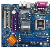
in) 7 8 9 10 11 12 13 1 PS2_USB_PWR1 Jumper 2 ATX 12V Connector (ATX12V1) 3 775-Pin CPU Socket 4 CPU Fan Connector (CPU_FAN1) 5 184-pin DDR DIMM Slots (DDR1- 2, Dual Channel) 6 Infrared Module Connector (IR1) 7 BIOS FWH Chip 8 Floppy Connector (FLOPPY1) 9 Primary IDE Connector (IDE1, Black) 10 - ASRock 775Dual-915GL | User Manual - Page 12
1.6 ASRock 8CH I/O 1 Parallel Port 2 RJ-45 Port 3 Side Speaker (Gray) 4 Rear Speaker ( the table below for connection details in accordance with the type of speaker you use. TABLE for Audio Output Connection Audio Output Channels Front Speaker Rear Speaker Central / Bass (No. 7) (No. 4) (No. - ASRock 775Dual-915GL | User Manual - Page 13
2 Installation 775Dual-915GL is a Micro ATX form factor (9.6" x 8.6", 24.4 x 21.8 cm) motherboard. Before you install the motherboard, study the configuration of your chassis to ensure that the motherboard fits into it. Make sure to unplug the power cord before installing or removing the motherboard - ASRock 775Dual-915GL | User Manual - Page 14
the installation of Intel 775-LAND CPU, please follow the steps below. 775-Pin Socket Overview Before you insert the 775-LAND CPU into the socket, please check if the CPU surface is unclean or if there is any bent pin on the socket. Do not force to insert the CPU into the socket if above situation - ASRock 775Dual-915GL | User Manual - Page 15
of the socket. Step 2-3. Carefully place the CPU into the socket by using a purely vertical motion. Step 2-4. Verify that the CPU is within the socket and properly mated to the orient keys. Step 3. Remove PnP Cap (Pick and Place Cap): Use your left hand index finger and thumb to support the load - ASRock 775Dual-915GL | User Manual - Page 16
Heatsink This motherboard is equipped with 775-Pin socket that supports Intel 775-LAND CPU. Please adopt the type of heatsink and cooling fan compliant with Intel 775-LAND CPU to dissipate heat. Before you installed the heatsink, you need to spray thermal interface material between the CPU and the - ASRock 775Dual-915GL | User Manual - Page 17
2.5 Installation of Memory Modules (DIMM) 775Dual-915GL motherboard provides two 184-pin DDR (Double Data Rate) DIMM slots, and supports Dual Channel Memory Technology. For dual channel configuration, you always need to install two identical (the same brand, speed, size and chip-type) memory modules - ASRock 775Dual-915GL | User Manual - Page 18
an ASRock MR card (optional) with v.92 Modem functionality. AGI slot: The AGI [ASRock Graphics Interface] slot is a special design that only supports compatible the BIOS onboard VGA selection into "En abled" if you want this motherboard to support Surround Display. Then the onboard VGA in Windows - ASRock 775Dual-915GL | User Manual - Page 19
BIOS onboard VGA selection into "Enabled", and start your computer with onboard VGA if you want this motherboard to support multi-monitors. For the detailed instruction and JR1 are short, both the front panel and the rear panel audio connectors can work. Clear CMOS (CLRCMOS1, 2-pin jumper) (see p. - ASRock 775Dual-915GL | User Manual - Page 20
) (39-pin IDE1, see p.11 No. 9) PIN1 IDE1 connect the blue end connect the black end to the motherboard to the IDE devices 80-conductor ATA 66/100 cable Note: Please refer to the instruction of your IDE device vendor for the details. Serial ATA Connectors (SATA1: see p.11 No. 17) (SATA2 - ASRock 775Dual-915GL | User Manual - Page 21
USB_PWR P-6 P+6 GND DUMMY 1 GND P+7 P-7 USB_PWR ASRock 8CH I/O accommodates 4 default USB 2.0 ports. If those support 2 additional USB 2.0 ports. This header supports an optional wireless transmitting and receiving infrared module. These connectors allow you to receive stereo audio input from sound - ASRock 775Dual-915GL | User Manual - Page 22
the black wire to the ground pin. GND +12V CPU_FAN_SPEED N/C Please connect a CPU fan cable to this connector and match the black wire to the ground pin. Please TTXD1 DDCD#1 This COM port header is used to support a COM port module. Please connect an ATX 12V power supply to this connector. 22 - ASRock 775Dual-915GL | User Manual - Page 23
2.10 Serial ATA (SATA) Hard Disks Installation This motherboard adopts Intel ICH6 south bridge chipset that supports Serial ATA (SATA) hard disks. You may install SATA hard disks on this motherboard for internal storage devices. This section will guide you to install the SATA hard disks. STEP 1: - ASRock 775Dual-915GL | User Manual - Page 24
UTILITY 3.1 Introduction This section explains how to use the BIOS SETUP UTILITY to configure your system. The BIOS FWH chip on the motherboard stores the BIOS SETUP UTILITY. You may run the BIOS SETUP UTILITY when you start up the computer. Please press during the Power-On-Self-Test (POST - ASRock 775Dual-915GL | User Manual - Page 25
Date [14:00:09] [Wed 01/05/2005] BIOS Version : 775Dual-915GL BIOS P1.00 Processor Type : Intel (R) CPU 2.40 GHz Processor Speed : 2400 Mhz Microcode Update : F24/1E Cache Size : 512KB Total Memory : 512MB with 8MB shared memory Dual-Channel Memory Mode DIMM 1 DIMM 2 : 256MB/166MHz - ASRock 775Dual-915GL | User Manual - Page 26
Defaults Save and Exit Exit v02.54 (C) Copyright 1985-2005, American Megatrends, Inc. CPU Host Frequency While entering setup, BIOS auto detects the present CPU host frequency of this motherboard. The actual CPU host frequency will show in the following item. Boot Failure Guard Enable or disable - ASRock 775Dual-915GL | User Manual - Page 27
option will be hidden if the current CPU does not support No-Excute Memory Protection. Enhance Halt State All processors support the Halt State (C1). The C1 state is supported through the native processor instructions HLT and MWAIT and requires no hardware support from the chipset. In the C1 power - ASRock 775Dual-915GL | User Manual - Page 28
BIOS SETUP UTILITY Advanced Chipset Configuration DRAM Frequency [Auto] Flexibility Option [Disabled] Configure DRAM Timing by SPD [Enabled] DRAM CAS# Latency [Auto] Onboard VGA Selection Aperture Size Select [Auto] [256MB] OnBoard LAN OnBoard AC'97 Audio , the motherboard will detect - ASRock 775Dual-915GL | User Manual - Page 29
Select [Auto], [Enabled] or [Disabled] for the onboard AC'97 Audio feature. OnBoard MC'97 Modem Select [Auto] or [Disabled] for the onboard MC'97 Modem feature. 3.3.3 ACPI Configuration BIOS SETUP UTILITY Advanced ACPI Configuration Suspend To RAM Restore on AC/Power Loss Ring-In Power On PCI - ASRock 775Dual-915GL | User Manual - Page 30
) to power on the system. 3.3.4 IDE Configuration BIOS SETUP UTILITY Advanced IDE Configuration ATA/IDE Configuration SATA1 SATA2 SATA1, SATA3 will not work. Because Intel® ICH6 south bridge only supports four IDE devices under legacy OS (Windows NT), you have to choose [SATA 1, SATA 2, SATA 3, - ASRock 775Dual-915GL | User Manual - Page 31
Master" as the example in the following instruction. BIOS SETUP UTILITY Advanced Primary IDE Master Device Vendor Disk :ST340014A :40.0 GB :Supported :16Sectors :4 :MultiWord DMA-2 :Ultra DMA-5 :Supported [Auto] [Auto] [Auto] MB under DOS and Windows; for Netware and UNIX user, select [Disabled] to - ASRock 775Dual-915GL | User Manual - Page 32
32-Bit Data Transfer Use this item to enable 32-bit access to maximize the IDE hard disk data transfer rate. 3.3.5 PCIPnP Configuration BIOS SETUP UTILITY Advanced PCI / PnP Configuration WARNING: Setting wrong values in below actions may cause system to malfunction. PCI Latency Timer PCI IDE - ASRock 775Dual-915GL | User Manual - Page 33
3.3.6 Floppy Configuration In this section, you may configure the type of your floppy drive. BIOS SETUP UTILITY Advanced Floppy Configuration Floppy A Floppy B [1.44 MB 312"] [Disabled] Select the type of floppy drive connected to the system. +F1 F9 F10 ESC Select Screen Select Item Change - ASRock 775Dual-915GL | User Manual - Page 34
Parallel Port Address Use this item to set the address for the onboard parallel port or disable it. Configuration options: [Disabled], [378], and [278]. Parallel Port Mode Use this item to set the operation mode of the parallel port. The default value is [ECP+EPP]. If this option is set to [ECP+EPP - ASRock 775Dual-915GL | User Manual - Page 35
controller. USB 2.0 Support Use this item to enable or disable the USB 2.0 support. Legacy USB Support Use this item to enable or disable the support to emulate legacy of the CPU temperature, motherboard temperature, CPU fan speed, chassis fan speed, and the critical voltage. BIOS SETUP UTILITY - ASRock 775Dual-915GL | User Manual - Page 36
it will display the available devices on your system for you to configure the boot settings and the boot priority. Main Advanced BIOS SETUP UTILITY H/W Monitor Boot Security Exit Boot Settings Boot Settings Configuration Configure Settings during System Boot. 1st Boot Device 2nd Boot Device - ASRock 775Dual-915GL | User Manual - Page 37
you may set or change the supervisor/user password for the system. For the user password, you may also clear it. BIOS SETUP UTILITY Main Advanced H/W Monitor Boot Security Exit Security Settings Supervisor Password : Not Installed User Password : Not Installed Change Supervisor Password - ASRock 775Dual-915GL | User Manual - Page 38
and exit setup?" Select [OK] to save the changes and exit the BIOS SETUP UTILITY. Discard Changes and Exit When you select this option, it message, "Discard changes and exit setup?" Select [OK] to exit the BIOS SETUP UTILITY without saving any changes. Discard Changes When you select this option - ASRock 775Dual-915GL | User Manual - Page 39
This motherboard is equipped with Intel LGA 775 socket, which is a new CPU socket interface that Intel has released. Since it has several tiny pins, whcih are easily to be damaged by improper handling, ASRock sincerely presents you a clear installation guide through this "LGA 775 CPU Installation
-
 1
1 -
 2
2 -
 3
3 -
 4
4 -
 5
5 -
 6
6 -
 7
7 -
8
-
9
-
10
-
11
-
12
-
13
-
14
-
15
-
16
-
17
-
18
-
19
-
20
-
21
-
22
-
23
-
24
-
25
-
26
-
27
-
28
-
29
-
30
-
31
-
32
-
33
-
34
-
35
-
36
-
37
-
38
-
39
 |
 |

1
775Dual-915GL
User Manual
Version 1.1
Published June 2005
Copyright©2005 ASRock INC. All rights reserved.