ASRock 775VM8 User Manual
ASRock 775VM8 Manual
 |
View all ASRock 775VM8 manuals
Add to My Manuals
Save this manual to your list of manuals |
ASRock 775VM8 manual content summary:
- ASRock 775VM8 | User Manual - Page 1
775VM8 User Manual Version 1.0 Published April 2005 Copyright©2005 ASRock INC. All rights reserved. 1 - ASRock 775VM8 | User Manual - Page 2
any form or by any means, except duplication of documentation by the purchaser for backup purpose, without written consent of ASRock Inc. Products and corporate names appearing in this manual may or may not be registered trademarks or copyrights of their respective companies, and are used only for - ASRock 775VM8 | User Manual - Page 3
Installing Windows XP 64-bit With RAID Functions 22 2.12 Installing Windows 98 / ME / 2000 / XP / XP 64-bit Without RAID Functions 22 3. BIOS SETUP UTILITY 23 3.1 Introduction 23 3.1.1 BIOS Menu Bar 23 3.1.2 Navigation Keys 24 3.2 Main Screen 24 3.3 Advanced Screen 24 3.3.1 CPU Configuration - ASRock 775VM8 | User Manual - Page 4
35 3.6 Security Screen 36 3.7 Exit Screen 37 4. Software Support 38 4.1 Install Operating System 38 4.2 Support CD Information 38 4.2.1 Running Support CD 38 4.2.2 Drivers Menu 38 4.2.3 Utilities Menu 38 4.2.4 "LGA 775 CPU Installation Live Demo" Program.... 38 4.2.5 Contact Information 38 - ASRock 775VM8 | User Manual - Page 5
any modifications of this manual occur, the updated version will be available on ASRock website without further notice. You may find the latest memory and CPU support lists on ASRock website as well. ASRock website http://www.asrock.com 1.1 Package Contents ASRock 775VM8 Motherboard (Micro ATX Form - ASRock 775VM8 | User Manual - Page 6
cm CPU: 775-Pin Socket supporting Intel® Pentium® 4 / Celeron® processor (in 775-land LGA package) Chipsets: North Bridge: VIA PM800, FSB @ 800/533 MHz, with Intel® Hyper-Threading Technology ready (see CAUTION 1) South Bridge: VIA VT8237R, supports USB 2.0, ATA 133, SATA 1.5Gb/s Memory - ASRock 775VM8 | User Manual - Page 7
remember to spray thermal grease between the CPU and the heatsink when you install the PC system. 3. Do NOT use a 3.3V AGP card on the AGP slot of this motherboard! It may cause permanent damage! 4. Power Management for USB 2.0 works fine under Microsoft® Windows® XP SP1 / 2000 SP4. It may not work - ASRock 775VM8 | User Manual - Page 8
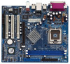
USB0 B: USB1 Top: RJ-45 USB 2.0 T: USB4 B: USB5 1 IR1 USB4_5 ATXPWR1 AGP 8X VPIMACh80ip0set IDE2 Super I/O LAN PHY 4Mb BIOS AUX1 CD1 Audio CODEC 1 AUDIO1 JR1 JL1 1.5V_AGP1 PCI 1 ` 775VM8 PCI 2 USB2.0 PCI 3 5.1CH FLOPPY1 AMR1 CLRCMOS1 CMOS Battery VIA VT8237R 1 USB67 PANEL 1 PLED - ASRock 775VM8 | User Manual - Page 9
1.4 ASRock I/O PlusTM 1 11 10 9 1 Parallel Port 2 RJ-45 Port 3 Line In (Light Blue) 4 Line Out (Lime) 5 Microphone (Pink) 6 Shared USB 2.0 Ports (USB45) 2 3 4 5 8 7 6 7 USB 2.0 Ports (USB01) 8 USB 2.0 Ports (USB23) 9 VGA Port 10 PS/2 Keyboard Port (Purple) 11 PS/2 Mouse Port (Green) 9 - ASRock 775VM8 | User Manual - Page 10
Installation 775VM8 is a Micro ATX form factor (9.6" x 8.2", 24.4 x 20.8 cm) motherboard. Before you install the motherboard, study the configuration of your chassis to ensure that the motherboard fits into it. Make sure to unplug the power cord before installing or removing the motherboard. Failure - ASRock 775VM8 | User Manual - Page 11
or if there is any bent pin on the socket. Do not force to insert the CPU into the socket if above situation is found. Otherwise, the CPU will be seriously damaged. Step 1. Open the socket: CPU Marked Corner Step 1-1. Disengaging the lever by depressing Lift Lever Up to 90° down and out - ASRock 775VM8 | User Manual - Page 12
the socket by using a purely vertical motion. Step 2-4. Verify that the CPU is within the socket and properly mated to the orient keys. Step 3. Remove PnP Cap (Pick and Place Cap): Use your left hand index finger and thumb to support the load plate edge, engage PnP cap with right hand thumb - ASRock 775VM8 | User Manual - Page 13
are securely fastened and in good contact with each other. Then connect the CPU fan to the CPU_FAN connector (CPU_FAN1, see page 8, No. 29). For proper installation, please kindly refer to the instruction manuals of your CPU fan and heatsink. Below is an example to illustrate the installation of the - ASRock 775VM8 | User Manual - Page 14
2.5 Installation of Memory Modules (DIMM) 775VM8 motherboard provides two 184-pin DDR (Double Data Rate) break The DIMM only fits in one correct orientation. It will cause permanent damage to the motherboard and the DIMM if you force the DIMM into the slot at incorrect orientation. Step 3. Firmly - ASRock 775VM8 | User Manual - Page 15
3 PCI slots, 1 AMR slot, and 1 AGP slot on 775VM8 motherboard. PCI slots: PCI slots are used to install expansion cards that have the 32-bit PCI interface. AMR slot: The AMR slot is used to insert an ASRock MR card with v.92 Modem functionality. AGP slot: The AGP slot is used to install a graphics - ASRock 775VM8 | User Manual - Page 16
1) +5V +5VSB +5VSB (standby) for PS/2 or USB wake up events. Note: To select +5VSB, it requires JR1 are short, both the front panel and the rear panel audio connectors can work. Clear CMOS (CLRCMOS1, 2-pin jumper) (see when you just finish updating the BIOS, you must boot up the system first - ASRock 775VM8 | User Manual - Page 17
ATA (SATA) connectors support SATA data cables for internal storage devices. The current SATA interface allows up to 1.5 Gb/s data transfer rate. Serial ATA (SATA) Data Cable Either end of the SATA data cable can be connected to the SATA hard disk or the SATA connector on the motherboard. 17 - ASRock 775VM8 | User Manual - Page 18
using the front panel USB ports by attaching the front panel USB cable to this connector (USB4_5), the USB ports 4,5 on ASRock I/O PlusTM will not be able to function. This header supports an optional wireless transmitting and receiving infrared module. Internal Audio Connectors (4-pin CD1, 4-pin - ASRock 775VM8 | User Manual - Page 19
the chassis fan cable to this connector and match the black wire to the ground pin. Please connect the CPU fan cable to this connector and match the black wire to the ground pin. Please connect an ATX #1 CCTS#1 1 RRI#1 RRTS#1 GND TTXD1 DDCD#1 This COM1 connector supports a serial port module. 19 - ASRock 775VM8 | User Manual - Page 20
Connect the other end of the SATA data cable to the SATA hard disk. 2.10 Hot Plug and Hot Swap Functions for SATA HDDs 775VM8 motherboard supports Hot Plug and Hot Swap functions for SATA Devices. NOTE What is Hot Plug Function? If the SATA HDDs are NOT set for RAID configuration, it is called "Hot - ASRock 775VM8 | User Manual - Page 21
the document in the Support CD, "Guide to SATA Hard Disks Installation and RAID Configuration", which is located in the folder at the following path: .. \ SATA RAID BIOS STEP 3: Install Windows 2000 / Windows XP OS on your system. After making a SATA driver diskette and using "SATA RAID BIOS" to set - ASRock 775VM8 | User Manual - Page 22
SATA RAID BIOS and the document in the support CD, "Guide to VIA RAID Tool", which is located in the folder at the following path: .. \ VIA RAID Tool 1. Windows 98 / Windows ME does not support RAID functions. 2. If you want to use "VIA RAID Tool" in Windows environment, please install SATA drivers - ASRock 775VM8 | User Manual - Page 23
the BIOS SETUP UTILITY to configure your system. The Flash Memory on the motherboard stores the BIOS SETUP UTILITY. You may run the BIOS SETUP off and then back on. Because the BIOS software is constantly being updated, the following BIOS setup screens and descriptions are for reference purpose - ASRock 775VM8 | User Manual - Page 24
BIOS SETUP UTILITY To jump to the BIOS Version : 775VM8 BIOS P1.00 Processor Type : Intel (R) CPU 3.20 GHz Processor Speed : 3200 MHz Cache Size : 1024KB Microcode Update : 0F34/0E Total Memory DIMM 1 DIMM 2 : 256MB with 64MB shared memory following items: CPU Configuration, Chipset - ASRock 775VM8 | User Manual - Page 25
PCIPnP Configuration Floppy Configuration SuperIO Configuration USB Configuration Configure CPU Select Screen Select Item Enter Go to Megatrends, Inc. CPU Host Frequency While entering setup, BIOS auto detects the present CPU host frequency of this motherboard. The actual CPU host frequency will - ASRock 775VM8 | User Manual - Page 26
Windows® XP. Set to [Auto] if using Microsoft® Windows® XP, or Linux kernel version 2.4.18 or higher. This option will be hidden if the installed CPU does not support hidden if the current CPU does not support No-Excute Memory Protection. 3.3.2 Chipset Configuration BIOS SETUP UTILITY Advanced - ASRock 775VM8 | User Manual - Page 27
motherboard, you may select [Auto], [8X] or [4X] as the AGP mode. If the installed AGP card is a 4X-AGP card, then you may set the AGP mode as [Auto], [4X], [2X], or [1X]. AGP Fast Write This allows you to enable or disable the feature of AGP fast write protocol support. Onboard AGP Share Memory - ASRock 775VM8 | User Manual - Page 28
Select [Auto], [Enabled], or [Disabled] for the onboard AC'97 Audio feature. OnBoard MC'97 Modem Select [Auto] or [Disabled] for the onboard MC'97 Modem feature. 3.3.3 ACPI Configuration BIOS SETUP UTILITY Advanced ACPI Configuration Suspend To RAM Restore on AC / Power Loss Ring-In Power On - ASRock 775VM8 | User Manual - Page 29
If you don't want to operate RAID function on SATA HDDs, please select [non-RAID]. IDE Device Configuration You may set the IDE configuration for the device that you specify. We will use the "Primary IDE Master" as the example in the following instruction, which can be applied to the configurations - ASRock 775VM8 | User Manual - Page 30
automatically detect the hard disk drive. After selecting the hard disk information into BIOS, use a disk utility, such as FDISK, to partition and format the new the LBA/Large mode for a hard disk > 512 MB under DOS and Windows; for Netware and UNIX user, select [Disabled] to disable the LBA/Large - ASRock 775VM8 | User Manual - Page 31
to enable or disable the PCI IDE BusMaster feature. 3.3.6 Floppy Configuration In this section, you may configure the type of your floppy drive. BIOS SETUP UTILITY Advanced Floppy Configuration Floppy A Floppy B [1.44 MB 312"] [Disabled] Select the type of floppy drive connected to the system - ASRock 775VM8 | User Manual - Page 32
Address Parallel Port Mode EPP Version ECP Mode DMA Channel Parallel Port IRQ [Enabled] [3F8 / IRQ4] [Disabled] [378] [ECP + EPP] [1.9] [DMA3] [IRQ7] Allow BIOS to Enable or Disable Floppy Controller. +F1 F9 F10 ESC Select Screen Select Item Change Option General Help Load Defaults Save and Exit - ASRock 775VM8 | User Manual - Page 33
3.3.8 USB Configuration BIOS SETUP UTILITY Advanced USB Configuration USB Controller USB 2.0 Support Legacy USB Support [Enabled] [Enabled] [Disabled] To enable or disable the onboard USB controllers. +F1 F9 F10 ESC Select Screen Select Item Change Option General Help Load Defaults Save and - ASRock 775VM8 | User Manual - Page 34
you to monitor the status of the hardware on your system, including the parameters of the CPU temperature, motherboard temperature, CPU fan speed, chassis fan speed, and the critical voltage. BIOS SETUP UTILITY Main Advanced H/W Monitor Boot Security Exit Hardware Health Event Monitoring - ASRock 775VM8 | User Manual - Page 35
-2003, American Megatrends, Inc. Boot From Network Use this item to enable or disable the Boot From Network feature. VIA SATA Raid Utility Use this to enable or disable VIA VT8237 SATA Raid BIOS Utility during POST. Boot Up Num-Lock If this item is set to [On], it will automatically activate the - ASRock 775VM8 | User Manual - Page 36
you may set or change the supervisor/user password for the system. For the user password, you may also clear it. BIOS SETUP UTILITY Main Advanced H/W Monitor Boot Security Exit Security Settings Supervisor Password : Not Installed User Password : Not Installed Change Supervisor Password - ASRock 775VM8 | User Manual - Page 37
and exit setup?" Select [OK] to save the changes and exit the BIOS SETUP UTILITY. Discard Changes and Exit When you select this option, it message, "Discard changes and exit setup?" Select [OK] to exit the BIOS SETUP UTILITY without saving any changes. Discard Changes When you select this option - ASRock 775VM8 | User Manual - Page 38
2000 / XP. Because motherboard settings and hardware options vary, use the setup procedures in this chapter for general reference only. Refer to your OS documentation for more information. 4.2 Support CD Information The Support CD that came with the motherboard contains necessary drivers and useful
-
 1
1 -
 2
2 -
 3
3 -
 4
4 -
 5
5 -
 6
6 -
 7
7 -
8
-
9
-
10
-
11
-
12
-
13
-
14
-
15
-
16
-
17
-
18
-
19
-
20
-
21
-
22
-
23
-
24
-
25
-
26
-
27
-
28
-
29
-
30
-
31
-
32
-
33
-
34
-
35
-
36
-
37
-
38
 |
 |

1
775VM8
User Manual
Version 1.0
Published April 2005
Copyright©2005 ASRock INC. All rights reserved.