ASRock 775VM800Pro-DDR2 User Manual
ASRock 775VM800Pro-DDR2 Manual
 |
View all ASRock 775VM800Pro-DDR2 manuals
Add to My Manuals
Save this manual to your list of manuals |
ASRock 775VM800Pro-DDR2 manual content summary:
- ASRock 775VM800Pro-DDR2 | User Manual - Page 1
775VM800Pro-DDR2 User Manual Version 1.0 Published September 2005 Copyright©2005 ASRock INC. All rights reserved. 1 - ASRock 775VM800Pro-DDR2 | User Manual - Page 2
any form or by any means, except duplication of documentation by the purchaser for backup purpose, without written consent of ASRock Inc. Products and corporate names appearing in this manual may or may not be registered trademarks or copyrights of their respective companies, and are used only for - ASRock 775VM800Pro-DDR2 | User Manual - Page 3
Motherboard Layout 9 1.4 ASRock I/O Plus 10 TM 2. Installation 11 2.1 Screw Holes 11 2.2 Pre-installation Precautions 11 2.3 CPU Installation 12 2.4 Installation of CPU Fan and Heatsink 14 2.5 Installation of Memory 23 3. BIOS SETUP UTILITY 24 3.1 Introduction 24 3.1.1 BIOS Menu Bar 24 - ASRock 775VM800Pro-DDR2 | User Manual - Page 4
4. Software Support 42 4.1 Install Operating System 42 4.2 Support CD Information 42 4.2.1 Running Support CD 42 4.2.2 Drivers Menu 42 4.2.3 Utilities Menu 42 4.2.4 "LGA 775 CPU Installation Live Demo" Program.... 42 4.2.5 Contact Information 42 4 - ASRock 775VM800Pro-DDR2 | User Manual - Page 5
latest memory and CPU support lists on ASRock website as well. ASRock website http://www.asrock.com 1.1 Package Contents ASRock 775VM800Pro-DDR2 Motherboard (Micro ATX Form Factor: 9.6-in x 8.5-in, 24.4 cm x 21.6 cm) ASRock 775VM800Pro-DDR2 Quick Installation Guide ASRock 775VM800Pro-DDR2 Support CD - ASRock 775VM800Pro-DDR2 | User Manual - Page 6
Memory Hybrid Booster Expansion Slot Graphics Audio LAN Rear Panel I/O - Micro ATX Form Factor: 9.6-in x 8.5-in, 24.4 cm x 21.6 cm - 775-Pin Socket supporting Intel® Dual Core Pentium® XE and Pentium® D / Pentium® 4 / Celeron® D processor (in 775-land LGA package) - FSB 1066/800/533 MHz - Supports - ASRock 775VM800Pro-DDR2 | User Manual - Page 7
ports; 2 of them are shared with USB4_5) (see CAUTION 5) - 4Mb AMI BIOS - AMI Legal BIOS - Supports "Plug and Play" - ACPI 1.1 Compliance Wake Up Events - Supports jumperfree - SMBIOS 2.3.1 Support - Drivers, Utilities, AntiVirus Software - CPU Temperature Sensing - Chassis Temperature Sensing - CPU - ASRock 775VM800Pro-DDR2 | User Manual - Page 8
grease between the CPU and the heatsink when you install the PC system. 4. Do NOT use a 3.3V AGP card on the AGP slot of this motherboard! It may cause permanent damage! 5. Power Management for USB 2.0 works fine under Microsoft® Windows® XP SP1 / 2000 SP4. It may not work properly under Microsoft - ASRock 775VM800Pro-DDR2 | User Manual - Page 9
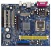
1.3 Motherboard Layout 1 234 PS2 Mouse FSB1066 Super I/O LAN PHY 4Mb BIOS AUX1 Audio CODEC CD1 1 AUDIO1 JR1 JL1 1.5V_AGP1 PCI 1 775VM800Pro-DDR2 PCI 2 USB2.0 PCI 3 3 x PCI Slots (PCI1- 3) 26 Flash Memory 27 Serial Port Connector (COM1) 28 Infrared Module Header (IR1) 29 Shared USB 2.0 - ASRock 775VM800Pro-DDR2 | User Manual - Page 10
1.4 ASRock I/O PlusTM 1 11 10 9 1 Parallel Port 2 RJ-45 Port 3 Line In (Light Blue) 4 Line Out (Lime) 5 Microphone (Pink) 6 Shared USB 2.0 Ports (USB45) 2 3 4 5 8 7 6 7 USB 2.0 Ports (USB01) 8 USB 2.0 Ports (USB23) 9 VGA Port 10 PS/2 Keyboard Port (Purple) 11 PS/2 Mouse Port (Green) 10 - ASRock 775VM800Pro-DDR2 | User Manual - Page 11
775VM800Pro-DDR2 is a Micro ATX form factor (9.6" x 8.5", 24.4 x 21.6 cm) motherboard. Before you install the motherboard, study the configuration of your chassis to ensure that the motherboard fits into it. Make sure to unplug the power cord before installing or removing the motherboard - ASRock 775VM800Pro-DDR2 | User Manual - Page 12
2.3 CPU Installation For the installation of Intel 775-LAND CPU, please follow the steps below. 775-Pin Socket Overview Before you insert the 775-LAND CPU into the socket, please check if the CPU surface is unclean or if there is any bent pin on the socket. Do not force to insert the CPU into the - ASRock 775VM800Pro-DDR2 | User Manual - Page 13
Pick and Place Cap): Use your left hand index finger and thumb to support the load plate edge, engage PnP cap with right hand thumb and peel off the PnP cap. 2. This cap must be placed if returning the motherboard for after service. Step 4. Close the socket: Step 4-1. Rotate the load plate onto the - ASRock 775VM800Pro-DDR2 | User Manual - Page 14
of CPU Fan and Heatsink This motherboard is equipped with 775-Pin socket that supports Intel 775-LAND CPU. Please CPU_FAN1, see page 9, No. 3). For proper installation, please kindly refer to the instruction manuals of your CPU fan and heatsink. Below is an example to illustrate the installation of - ASRock 775VM800Pro-DDR2 | User Manual - Page 15
2.5 Installation of Memory Modules (DIMM) 775VM800Pro-DDR2 motherboard provides two 240-pin DDRII (Double Data Rate) DIMM slots. It is not allowed to install DDR into DDRII slot; otherwise, this motherboard and DIMM may be damaged. Please make sure to disconnect power supply before adding or - ASRock 775VM800Pro-DDR2 | User Manual - Page 16
Slots) There are 3 PCI slots, 1 AMR slot, and 1 AGP slot on 775VM800Pro-DDR2 motherboard. PCI slots: PCI slots are used to install expansion cards that have the 32-bit PCI interface. AMR slot: The AMR slot is used to insert an ASRock MR card with v.92 Modem functionality. AGP slot: The AGP slot is - ASRock 775VM800Pro-DDR2 | User Manual - Page 17
2.7 Jumpers Setup The illustration shows how jumpers are setup. When the jumper cap is placed on pins, the jumper is "Short". If no jumper cap is placed on pins, the jumper is "Open". The illustration shows a 3-pin jumper whose pin1 and pin2 are "Short" when jumper cap is placed on these 2 pins. - ASRock 775VM800Pro-DDR2 | User Manual - Page 18
one IDE device on this motherboard, please set the IDE device as "Master". Please refer to the instruction of your IDE device vendor for see p.9, No. 15) SATA2 SATA1 These two Serial ATA (SATA) connectors support SATA data cables for internal storage devices. The current SATA interface allows up - ASRock 775VM800Pro-DDR2 | User Manual - Page 19
panel USB ports by attaching the front panel USB cable to this connector (USB4_5), the USB ports 4,5 on ASRock I/O PlusTM will not be able to function. This header supports an optional wireless transmitting and receiving infrared module. These connectors allow you to receive stereo audio input from - ASRock 775VM800Pro-DDR2 | User Manual - Page 20
may cause permanent damage! Serial port connector (9-pin COM1) (see p.9 item 27) RRXD1 DDTR#1 DDSR#1 CCTS#1 1 RRI#1 RRTS#1 GND TTXD1 DDCD#1 20 This COM1 connector supports a serial port module. - ASRock 775VM800Pro-DDR2 | User Manual - Page 21
supports Serial ATA (SATA) hard disks and RAID functions (RAID 0, 1, JBOD). You may install SATA hard disks on this motherboard for internal storage devices. This section will guide and Hot Swap Functions for SATA HDDs 775VM800Pro-DDR2 motherboard supports Hot Plug and Hot Swap functions for SATA - ASRock 775VM800Pro-DDR2 | User Manual - Page 22
functions, please follow the below steps. STEP 1: Make a SATA Driver Diskette. A. Insert the ASRock Support CD into your optical drive to boot your system. B. During POST the installation guide in the Support CD for proper configuration. Please refer to the document in the Support CD, "Guide to SATA - ASRock 775VM800Pro-DDR2 | User Manual - Page 23
"VIA RAID Tool Information" in Windows environment, please install SATA drivers from the Support CD again so that "VIA RAID Tool Information" will be installed / ME / 2000 / XP / XP 64-bit OS on your system. After setting up BIOS, you can start to install Windows 98 / ME / 2000 / XP / XP 64-bit on - ASRock 775VM800Pro-DDR2 | User Manual - Page 24
SETUP UTILITY 3.1 Introduction This section explains how to use the BIOS SETUP UTILITY to configure your system. The Flash Memory on the motherboard stores the BIOS SETUP UTILITY. You may run the BIOS SETUP UTILITY when you start up the computer. Please press during the Power-On-Self-Test (POST - ASRock 775VM800Pro-DDR2 | User Manual - Page 25
[17:00:09] [Tue 09/27/2005] BIOS Version : 775VM800Pro-DDR2 BIOS P1.00 Processor Type : Intel (R) CPU 3.20 GHz Processor Speed : 3200 MHz Cache Size : 1024KB Microcode Update : 0F34/0E Total Memory DDRII 1 DDRII 2 : 256MB with 64MB shared memory : 256MB/266MHz (DDRII533) : None Use [Enter - ASRock 775VM800Pro-DDR2 | User Manual - Page 26
Limit 'Intel (R) Virtualization tech. CPU Thermal Throttling No-Excute Memory Protection Enhance Halt State Hyper Threading Technology Intel (R) SpeedStep(tm) CPU Host Frequency While entering setup, BIOS auto detects the present CPU host frequency of this motherboard. The actual CPU host frequency - ASRock 775VM800Pro-DDR2 | User Manual - Page 27
the ratio actual value of this motherboard. Max CPUID Value Limit For Prescott support No-Excute Memory Protection. Enhance Halt State All processors support the Halt State (C1). The C1 state is supported through the native processor instructions HLT and MWAIT and requires no hardware support - ASRock 775VM800Pro-DDR2 | User Manual - Page 28
BIOS Frequency If [Auto] is selected, the motherboard will detect the memory module(s) inserted and assigns appropriate frequency automatically. 266MHz (DDRII 533)]. Flexibility Option The default value of this option is [Disabled]. It will allow better tolerance for memory compatibility when it - ASRock 775VM800Pro-DDR2 | User Manual - Page 29
select the proper access mode for the system. You may select between [Single Channel] and [Dual Channel] if you have properly set the dual channel memory configuration. DRAM Command Rate Use this to select among [2T Command] and [1T Command] for DRAM Command Rate. The default value is [2T Command - ASRock 775VM800Pro-DDR2 | User Manual - Page 30
address range used for graphics memory. It is recommended to leave this field at the default value unless the installed AGP card's specifications requires other sizes. AGP Mode The default value of this feature is set to [Auto]. If you install an 8X-AGP card on this motherboard, you may select [Auto - ASRock 775VM800Pro-DDR2 | User Manual - Page 31
OnBoard AC'97 Audio Select [Auto], [Enabled] or [Disabled] for the onboard AC'97 Audio feature. If you select [Auto], the onboard AC'97 Audio will be disabled when PCI Sound card is plugged. OnBoard MC'97 Modem Select [Auto] or [Disabled] for the onboard MC'97 Modem feature. Thermal Throttling - ASRock 775VM800Pro-DDR2 | User Manual - Page 32
3.3.3 ACPI Configuration BIOS SETUP UTILITY Advanced ACPI Configuration Suspend To RAM Restore on AC / Power Loss Ring-In Power On PCI Devices Power On PS / 2 Keyboard Power On RTC Alarm Power On [Disabled] [Power Off] [Disabled] [ - ASRock 775VM800Pro-DDR2 | User Manual - Page 33
" as the example in the following instruction, which can be applied to the configurations of " ", and "Secondary IDE Slave" as well. BIOS SETUP UTILITY Advanced Primary IDE Master Device Vendor Disk :ST340014A :40.0 GB :Supported :16Sectors :4 :MultiWord DMA-2 :Ultra DMA-5 :Supported [Auto] [Auto] [Auto] - ASRock 775VM800Pro-DDR2 | User Manual - Page 34
Installed] to disable the use of IDE device. [Auto]: Select [Auto] to automatically detect the hard disk drive. After selecting the hard disk information into BIOS, use a disk utility, such as FDISK, to partition and format the new IDE hard disk drives. This is necessary so that you can write or - ASRock 775VM800Pro-DDR2 | User Manual - Page 35
to enable or disable the PCI IDE BusMaster feature. 3.3.6 Floppy Configuration In this section, you may configure the type of your floppy drive. BIOS SETUP UTILITY Advanced Floppy Configuration Floppy A Floppy B [1.44 MB 312"] [Disabled] Select the type of floppy drive connected to the system - ASRock 775VM800Pro-DDR2 | User Manual - Page 36
Address Parallel Port Mode EPP Version ECP Mode DMA Channel Parallel Port IRQ [Enabled] [3F8 / IRQ4] [Disabled] [378] [ECP + EPP] [1.9] [DMA3] [IRQ7] Allow BIOS to Enable or Disable Floppy Controller. +F1 F9 F10 ESC Select Screen Select Item Change Option General Help Load Defaults Save and Exit - ASRock 775VM800Pro-DDR2 | User Manual - Page 37
3.3.8 USB Configuration BIOS SETUP UTILITY Advanced USB Configuration USB Controller USB 2.0 Support Legacy USB Support [Enabled] [Enabled] [Disabled] To enable or disable the onboard USB controllers. +F1 F9 F10 ESC Select Screen Select Item Change Option General Help Load Defaults - ASRock 775VM800Pro-DDR2 | User Manual - Page 38
the status of the hardware on your system, including the parameters of the CPU temperature, motherboard temperature, CPU fan speed, chassis fan speed, and the critical voltage. BIOS SETUP UTILITY Main Advanced H/W Monitor Boot Security Exit Hardware Health Event Monitoring CPU Temperature - ASRock 775VM800Pro-DDR2 | User Manual - Page 39
3.5.1 Boot Settings Configuration BIOS SETUP UTILITY Boot Boot Settings Configuration Boot From Network VIA SATA Raid From Network feature. VIA SATA Raid Utility Use this to enable or disable VIA VT8237R Plus SATA Raid BIOS Utility during POST. Boot Up Num-Lock If this item is set to [On], it will - ASRock 775VM800Pro-DDR2 | User Manual - Page 40
you may set or change the supervisor/user password for the system. For the user password, you may also clear it. BIOS SETUP UTILITY Main Advanced H/W Monitor Boot Security Exit Security Settings Supervisor Password : Not Installed User Password : Not Installed Change Supervisor Password - ASRock 775VM800Pro-DDR2 | User Manual - Page 41
and exit setup?" Select [OK] to save the changes and exit the BIOS SETUP UTILITY. Discard Changes and Exit When you select this option, it message, "Discard changes and exit setup?" Select [OK] to exit the BIOS SETUP UTILITY without saving any changes. Discard Changes When you select this option - ASRock 775VM800Pro-DDR2 | User Manual - Page 42
to your OS documentation for more information. 4.2 Support CD Information The Support CD that came with the motherboard contains necessary drivers and useful utilities that enhance the motherboard features. 4.2.1 Running The Support CD To begin using the support CD, insert the CD into your CD-ROM
-
 1
1 -
 2
2 -
 3
3 -
 4
4 -
 5
5 -
 6
6 -
 7
7 -
8
-
9
-
10
-
11
-
12
-
13
-
14
-
15
-
16
-
17
-
18
-
19
-
20
-
21
-
22
-
23
-
24
-
25
-
26
-
27
-
28
-
29
-
30
-
31
-
32
-
33
-
34
-
35
-
36
-
37
-
38
-
39
-
40
-
41
-
42
 |
 |

1
775VM800Pro-DDR2
User Manual
Version 1.0
Published September 2005
Copyright©2005 ASRock INC. All rights reserved.