ASRock 775XFire-eSATA2 User Manual
ASRock 775XFire-eSATA2 Manual
 |
View all ASRock 775XFire-eSATA2 manuals
Add to My Manuals
Save this manual to your list of manuals |
ASRock 775XFire-eSATA2 manual content summary:
- ASRock 775XFire-eSATA2 | User Manual - Page 1
775XFire-eSATA2+ User Manual Version 1.0 Published April 2006 Copyright©2006 ASRock INC. All rights reserved. 1 - ASRock 775XFire-eSATA2 | User Manual - Page 2
any form or by any means, except duplication of documentation by the purchaser for backup purpose, without written consent of ASRock Inc. Products and corporate names appearing in this manual may or may not be registered trademarks or copyrights of their respective companies, and are used only for - ASRock 775XFire-eSATA2 | User Manual - Page 3
Table for Windows® VistaTM Premium and Basic Logo 9 1.4 Supported PCI Express VGA Card List for AGI Express Slot (PCI Express x4 10 1.5 Motherboard Layout 11 1.6 ASRock 8CH_eSATAII I/O 12 2 Installation 13 2.1 Screw Holes 13 2.2 Pre-installation Precautions 13 2.3 CPU Installation 14 - ASRock 775XFire-eSATA2 | User Manual - Page 4
3.1.1 BIOS Menu Bar 41 3.1.2 Navigation Keys 42 3.2 Main Screen 42 3.3 Advanced Screen 42 3.3.1 CPU Configuration 43 3.3.2 Support 57 4.1 Install Operating System 57 4.2 Support CD Information 57 4.2.1 Running Support CD 57 4.2.2 Drivers Menu 57 4.2.3 Utilities Menu 57 4.2.4 "LGA 775 CPU - ASRock 775XFire-eSATA2 | User Manual - Page 5
CPU support lists on ASRock website as well. ASRock website http://www.asrock.com 1.1 Package Contents ASRock 775XFire-eSATA2+ Motherboard (ATX Form Factor: 12.0-in x 8.6-in, 30.5 cm x 21.8 cm) ASRock 775XFire-eSATA2+ Quick Installation Guide ASRock 775XFire-eSATA2+ Support CD (including LGA 775 CPU - ASRock 775XFire-eSATA2 | User Manual - Page 6
CAUTION 2) - Supports EM64T CPU - Northbridge: Intel® 945PL chipset - Southbridge: Intel® ICH7R - Dual Channel DDRII Memory Technology (see CAUTION 3) - 4 x DDRII DIMM slots - Support DDRII533 (see CAUTION 4) - Max. capacity: 2GB - CPU Frequency Stepless Control (see CAUTION 5) - ASRock U-COP (see - ASRock 775XFire-eSATA2 | User Manual - Page 7
CAUTION 11) - 4Mb AMI BIOS - AMI Legal BIOS - Supports "Plug and Play" - ACPI 1.1 Compliance Wake Up Events - Supports jumperfree - SMBIOS 2.3.1 Support - Drivers, Utilities, AntiVirus Software (Trial Version) - CPU Temperature Sensing - Chassis Temperature Sensing - CPU Fan Tachometer - Chassis Fan - ASRock 775XFire-eSATA2 | User Manual - Page 8
(Port Multiplier Technology is not supported with eSATAII interface on this motherboard.) 11. Power Management for USB 2.0 works fine under Microsoft® Windows® VistaTM / XP 64-bit / XP SP1 or SP2 / 2000 SP4. 12. Microsoft® Windows® VistaTM driver is not ready yet. We will update it to our website in - ASRock 775XFire-eSATA2 | User Manual - Page 9
who purchase this motherboard and plan to submit Windows® VistaTM Premium and Basic logo, please follow the below table for minimum hardware requirement. Please adopt the CPU, memory, and VGA that we suggest. CPU Memory VGA Celeron D 326 512MB Single Channel DX9.0 with WDDM Driver with 128bit VGA - ASRock 775XFire-eSATA2 | User Manual - Page 10
1.4 Supported PCI Express VGA Card List for AGI Express Slot (PCI Express x4) (for Windows® 2000/XP/XP 64-bit/VistaTM) updates of the supported PCI Express VGA card list for AGI Express slot (PCI Express x4), please visit our website for details. ASRock website: http://www.asrock.com/support - ASRock 775XFire-eSATA2 | User Manual - Page 11
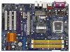
FSB1066 Intel 945PL Chipset eSATAII ATXPWR1 Top: LINE IN Center: FRONT Bottom: MIC IN Presler Conroe Dual Core CPU PCIE1 Super I/O 7 7 5 X F i r e - e S ATA 2 + ` PCIE2 PCI RAID IDE1 EXPRESS AGI_EXPRESS1 PCI 1 CMOS Battery CLRCMOS1 1 SATAII 4Mb BIOS LAN PHY PCI 2 AUDIO CODEC - ASRock 775XFire-eSATA2 | User Manual - Page 12
1.6 ASRock 8CH_eSATAII I/O 1 2 3 6 4 7 5 8 13 12 11 10 9 1 Parallel Port 2 RJ-45 Port 3 Side Speaker (Gray) 4 Rear Speaker (Black) 5 Central / Bass (Orange) 6 Line In (Light Blue) *7 Front Speaker ( - ASRock 775XFire-eSATA2 | User Manual - Page 13
775XFire-eSATA2+ is an ATX form factor (12.0" x 8.6", 30.5 x 21.8 cm) motherboard. Before you install the motherboard, study the configuration of your chassis to ensure that the motherboard fits into it. Make sure to unplug the power cord before installing or removing the motherboard. Failure - ASRock 775XFire-eSATA2 | User Manual - Page 14
the installation of Intel 775-LAND CPU, please follow the steps below. 775-Pin Socket Overview Before you insert the 775-LAND CPU into the socket, please check if the CPU surface is unclean or if there is any bent pin on the socket. Do not force to insert the CPU into the socket if above situation - ASRock 775XFire-eSATA2 | User Manual - Page 15
to use the cap tab to handle and avoid kicking off the PnP cap. 2. This cap must be placed if returning the motherboard for after service. Step 4. Close the socket: Step 4-1. Rotate the load plate onto the IHS. Step 4-2. While pressing down lightly on load plate, engage the load lever. Step - ASRock 775XFire-eSATA2 | User Manual - Page 16
Heatsink This motherboard is equipped with 775-Pin socket that supports Intel 775-LAND CPU. Please adopt the type of heatsink and cooling fan compliant with Intel 775-LAND CPU to dissipate heat. Before you installed the heatsink, you need to spray thermal interface material between the CPU and the - ASRock 775XFire-eSATA2 | User Manual - Page 17
2.5 Installation of Memory Modules (DIMM) 775XFire-eSATA2+ motherboard provides four 240-pin DDRII (Double Data Rate II) DIMM slots, and supports Dual Channel Memory Technology. For dual channel configuration, you always need to install identical (the same brand, speed, size and chip-type) DDRII - ASRock 775XFire-eSATA2 | User Manual - Page 18
them either in the set of yellow slots (DDRII_1 and DDRII_3), or in the set of orange slots (DDRII_2 and DDRII_4). 3. This motherboard does not support three or four above memory modules. Installing a DIMM Please make sure to disconnect power supply before adding or removing DIMMs or the system - ASRock 775XFire-eSATA2 | User Manual - Page 19
snap back in place and the DIMM is properly seated. 2.6 Expansion Slots (PCI, PCI Express, and AGI Express Slots) There are 3 PCI slots, 2 PCI Express slots, and 1 AGI Express slot (PCI Express x4) on this motherboard. PCI slots: PCI slots are used to install expansion cards that have the 32-bit - ASRock 775XFire-eSATA2 | User Manual - Page 20
. Currently CrossFireTM feature is only supported with Windows® XP with Service Pack 2; it may be supported with other OS in the future. What graphics cards work with CrossFireTM? A complete CrossFireTM system requires a CrossFireTM Ready motherboard, a CrossFireTM Edition graphics card and - ASRock 775XFire-eSATA2 | User Manual - Page 21
Step 3. Install the Radeon CrossFireTM Edition graphics card to PCI Express x16 slot. For the proper installation procedures, please refer (If you install two standard Radeon (CrossFireTM Ready) graphics cards to this motherboard, please skip this step.) DVI-DMS cable Connect the DVI-DMS cable to - ASRock 775XFire-eSATA2 | User Manual - Page 22
visit the websites below for installing the drivers that ATI recommends: A. ATI recommends Windows® XP Service Pack 2 or higher to be installed (If you have Windows® XP Service Pack 2 or higher installed in your system, there is no need to download it again): http://www.microsoft.com/windowsxp - ASRock 775XFire-eSATA2 | User Manual - Page 23
you will find "ATI Catalyst Control Center" on your desktop (ATI Catalyst driver should be version 5.10 or higher). You will find "ATI Catalyst Control compatible standard Radeon (CrossFireTM Ready) graphics card to this motherboard but not two Radeon CrossFireTM Edition graphics cards, please as - ASRock 775XFire-eSATA2 | User Manual - Page 24
Display Feature This motherboard supports Surround Display upgrade. With the external add-on PCI Express VGA card, you can easily enjoy the benefits of Surround Display feature. For the detailed instruction, please refer to the document at the following path in the Support CD: ..\ Surround Display - ASRock 775XFire-eSATA2 | User Manual - Page 25
the black end to the motherboard to the IDE devices 80-conductor ATA 66/100 cable Note: Please refer to the instruction of your IDE device vendor p.11, No. 34) eSATAII_TOP eSATAII_BOTTOM These two eSATA II connectors support SATA data cables for external SATAII function. The current eSATA II - ASRock 775XFire-eSATA2 | User Manual - Page 26
DUMMY 1 GND P+4 P-4 USB_PWR Besides two default USB 2.0 ports on the I/O panel, there are three USB 2.0 headers on this motherboard. Each USB 2.0 header can support two USB 2.0 ports. (9-pin USB23) (see p.11 No. 23) USB_PWR P-3 P+3 GND DUMMY 1 GND P+2 P-2 USB_PWR Infrared Module Header (5-pin - ASRock 775XFire-eSATA2 | User Manual - Page 27
supports Jack Sensing, but the panel wire on the chassis must support HDA to function correctly. Please follow the instruction in our manual and chassis manual BIOS Setup Windows CPU Fan Connector (4-pin CPU_FAN1) (see p.11 No. 6) +12V CPU_FAN_SPEED GND FAN_SPEED_CONTROL Please connect a CPU - ASRock 775XFire-eSATA2 | User Manual - Page 28
No. 2) Please connect an ATX 12V power supply to this connector. SLI/XFIRE Power Connector (4-pin SLI/XFIRE_POWER1) (see p.11 No. 3) SLI/XFIRE_POWER1 the black end (A) of HDMI_SPDIF cable to the HDMI_SPDIF header on the motherboard. Then connect the white end (B or C) of HDMI_SPDIF cable to the - ASRock 775XFire-eSATA2 | User Manual - Page 29
USB Bracket This USB bracket can support 2 additional USB 2.0 ports besides the I/O panel. Please connect the blue connector on the cable of this USB bracket to the USB 2.0 header (USB23, USB45, or USB67) and fasten the USB bracket to the chassis with screws. 29 - ASRock 775XFire-eSATA2 | User Manual - Page 30
, please carefully follow the below steps. Step 1. Install the HDMI VGA card to the• PCI Express Graphics slot on this motherboard. For the proper installation of HDMI VGA card, please refer to the installation guide on page 19. Step 2. Connect the black end (A) of HDMI_SPDIF cable to the HDMI_SPDIF - ASRock 775XFire-eSATA2 | User Manual - Page 31
eSATAII Interface Introduction What is eSATAII? This motherboard supports eSATAII interface, the external SATAII specification. and eSATAII_BOTTOM 1. If you just plan to install one eSATAII device to this motherboard, it is recommended to enable the bottom eSATAII port of the I/O shield. - ASRock 775XFire-eSATA2 | User Manual - Page 32
2. If you plan to install two eSATAII devices to this motherboard, you need to enable both the top and the bottom eSATAII ports of the I/O shield. In order to enable the top and the bottom eSATAII - ASRock 775XFire-eSATA2 | User Manual - Page 33
Comparison between eSATAII and other devices IEEE 1394 USB 2.0 SATA eSATAII/SATAII 400Mb/s 480Mb/s 1.5Gb/s (1500Mb/s) 3.0Gb/s (3000Mb/s) 33 - ASRock 775XFire-eSATA2 | User Manual - Page 34
guide. Some default setting of SATAII hard disks may not be at SATAII mode, which operate with the best performance. In order to enable SATAII function, please follow the below instruction website for details: http://www.hitachigst.com/hdd/support/download.htm The above examples are just for your - ASRock 775XFire-eSATA2 | User Manual - Page 35
south bridge chipset that supports Serial ATA (SATA) / Serial ATAII (SATAII) hard disks and RAID (RAID 0, RAID 1, RAID 10, RAID 5, and Intel Matrix Storage) functions. You may install SATA / SATAII hard disks on this motherboard for internal storage devices. This section will guide you to install - ASRock 775XFire-eSATA2 | User Manual - Page 36
motherboard supports Hot Plug and Hot Swap functions for SATA / SATAII / eSATAII Devices. Intel ICH7R south bridge chipset provides hardware support 16 Driver Installation Guide To install the drivers to your system, please insert the support CD to your optical drive first. Then, the drivers - ASRock 775XFire-eSATA2 | User Manual - Page 37
document in the Support CD, "Guide to SATA Hard Disks Installation and RAID Configuration", which is located in the folder at the following path: .. \ RAID Installation Guide STEP 4: Install Windows® 2000 / Windows® XP / Windows® XP 64-bit OS on your system. After making a SATA driver diskette and - ASRock 775XFire-eSATA2 | User Manual - Page 38
Intel(R) 82801GR/GH SATA RAID Controller (Desktop ICH7R-Windows XP64)" for Windows® XP 64-bit. 5. Finish the Windows® installation and install all necessary drivers. 6. Install the Intel(R) Matrix Storage Manager software via the CD-ROM included with your motherboard or after downloading it from the - ASRock 775XFire-eSATA2 | User Manual - Page 39
® 2000 / XP / XP 64-bit on your SATA HDDs without RAID functions, please follow the below steps. The installation procedures for Windows® VistaTM are subject to change. STEP 1: Set Up BIOS. A. Enter BIOS SETUP UTILITY Advanced screen IDE Configuration. B. Set "ATA/IDE Configuration" to [Enhanced - ASRock 775XFire-eSATA2 | User Manual - Page 40
(Desktop ICH7R-Windows XP64)" for Windows® XP 64-bit. 2.19 Untied Overclocking Technology This motherboard supports Untied Overclocking Technology, which means during overclocking, FSB enjoys better margin due to fixed PCI bus. You may set "CPU Host Frequency" option of BIOS setup to [Auto - ASRock 775XFire-eSATA2 | User Manual - Page 41
the BIOS SETUP UTILITY to configure your system. The BIOS FWH chip on the motherboard stores the BIOS SETUP UTILITY. You may run the BIOS SETUP off and then back on. Because the BIOS software is constantly being updated, the following BIOS setup screens and descriptions are for reference purpose - ASRock 775XFire-eSATA2 | User Manual - Page 42
Overview System Time System Date [14:00:09] [Fri 04/21/2006] BIOS Version : 775XFire-eSATA2+ BIOS P1.00 Processor Type : Intel (R) CPU 3.40 GHz (64bit supported) Processor Speed : 3400 MHz Microcode Update : F34/17 Cache Size : 1024KB Total Memory DDRII 1 DDRII 2 DDRII 3 DDRII 4 : 256MB - ASRock 775XFire-eSATA2 | User Manual - Page 43
Defaults Save and Exit Exit v02.54 (C) Copyright 1985-2005, American Megatrends, Inc. CPU Host Frequency While entering setup, BIOS auto detects the present CPU host frequency of this motherboard. The actual CPU host frequency will show in the following item. Boot Failure Guard Enable or disable - ASRock 775XFire-eSATA2 | User Manual - Page 44
appear to allow you changing the ratio value of this motherboard. Enhance Halt State All processors support the Halt State (C1). The C1 state is supported through the native processor instructions HLT and MWAIT and requires no hardware support from the chipset. In the C1 power state, the processor - ASRock 775XFire-eSATA2 | User Manual - Page 45
BIOS SETUP UTILITY Advanced Chipset Configuration DRAM Frequency [Auto] Flexibility Option [Disabled] Configure DRAM Timing by SPD [Enabled] DRAM CAS# Latency [Auto] Boot Graphic Adapter Priority [PCI If [Auto] is selected, the motherboard will detect the memory module(s) inserted and - ASRock 775XFire-eSATA2 | User Manual - Page 46
Adapter Priority This allows you to select [PCI/PCIE] or [PCIE/PCI] as the boot graphic adapter priority. The default value is [PCI/PCIE]. PCIE Frequency Use this option to adjust PCIE frequency. The default value is [Auto]. If you set this option to [Manual], you are allowed to adjust the actual - ASRock 775XFire-eSATA2 | User Manual - Page 47
3.3.3 ACPI Configuration BIOS SETUP UTILITY Advanced ACPI Configuration Suspend To RAM Restore on AC/Power Loss Ring-In Power On PCI Devices Power On PS / -detect or disable the Sus pend-to-RAM feature. Select [Auto] will enable this feature if the system supports it. Restore on AC/Power Loss This - ASRock 775XFire-eSATA2 | User Manual - Page 48
Configuration BIOS SETUP UTILITY select [Compatible] when you install legacy OS (Windows NT). If native OS (Windows 2000 / XP) is installed, please select [ mode does not have these advantages. 2. Only AHCI and RAID modes support Hot Plug function. When [Compatible] is selected Combined Option - ASRock 775XFire-eSATA2 | User Manual - Page 49
Because Intel® ICH7R south bridge only supports four IDE devices under legacy OS (Windows NT), you have to choose [SATA0, 1, 2, 3], [ to automatically detect the hard disk drive. After selecting the hard disk information into BIOS, use a disk utility, such as FDISK, to partition and format the new - ASRock 775XFire-eSATA2 | User Manual - Page 50
LBA/Large mode for a hard disk > 512 MB under DOS and Windows; for Netware and UNIX user, select [Disabled] to disable the LBA/ IDE hard disk data transfer rate. 3.3.5 PCIPnP Configuration BIOS SETUP UTILITY Advanced Advanced PCI / PnP Settings WARNING: Setting wrong values in below actions - ASRock 775XFire-eSATA2 | User Manual - Page 51
Channel Parallel Port IRQ OnBoard Game Port OnBoard MIDI Port [Enabled] [3F8 / IRQ4] [Disabled] [378] [ECP + EPP] [1.9] [DMA3] [IRQ7] [Enabled] [Disabled] Allow BIOS to Enable or Disable Floppy Controller. +F1 F9 F10 ESC Select Screen Select Item Change Option General Help Load Defaults Save and - ASRock 775XFire-eSATA2 | User Manual - Page 52
Parallel Port Address Use this item to set the address for the onboard parallel port or disable it. Configuration options: [Disabled], [378], and [278]. Parallel Port Mode Use this item to set the operation mode of the parallel port. The default value is [ECP+EPP]. If this option is set to [ECP+EPP - ASRock 775XFire-eSATA2 | User Manual - Page 53
controller. USB 2.0 Support Use this item to enable or disable the USB 2.0 support. Legacy USB Support Use this item to enable or disable the support to emulate legacy of the CPU temperature, motherboard temperature, CPU fan speed, chassis fan speed, and the critical voltage. BIOS SETUP UTILITY - ASRock 775XFire-eSATA2 | User Manual - Page 54
( C) The default value of tolerance is [2], which means the error of the target CPU temperature will be within 2 C. Target Fan Speed Use this option to set the target the boot settings and the boot priority. Main Advanced BIOS SETUP UTILITY H/W Monitor Boot Security Exit Boot Settings Boot - ASRock 775XFire-eSATA2 | User Manual - Page 55
you may set or change the supervisor/user password for the system. For the user password, you may also clear it. BIOS SETUP UTILITY Main Advanced H/W Monitor Boot Security Exit Security Settings Supervisor Password : Not Installed User Password : Not Installed Change Supervisor Password - ASRock 775XFire-eSATA2 | User Manual - Page 56
and exit setup?" Select [OK] to save the changes and exit the BIOS SETUP UTILITY. Discard Changes and Exit When you select this option, it message, "Discard changes and exit setup?" Select [OK] to exit the BIOS SETUP UTILITY without saving any changes. Discard Changes When you select this option - ASRock 775XFire-eSATA2 | User Manual - Page 57
This motherboard is equipped with Intel LGA 775 socket, which is a new CPU socket interface that Intel has released. Since it has several tiny pins, whcih are easily to be damaged by improper handling, ASRock sincerely presents you a clear installation guide through this "LGA 775 CPU Installation
-
 1
1 -
 2
2 -
 3
3 -
 4
4 -
 5
5 -
 6
6 -
 7
7 -
8
-
9
-
10
-
11
-
12
-
13
-
14
-
15
-
16
-
17
-
18
-
19
-
20
-
21
-
22
-
23
-
24
-
25
-
26
-
27
-
28
-
29
-
30
-
31
-
32
-
33
-
34
-
35
-
36
-
37
-
38
-
39
-
40
-
41
-
42
-
43
-
44
-
45
-
46
-
47
-
48
-
49
-
50
-
51
-
52
-
53
-
54
-
55
-
56
-
57
 |
 |

1
775XFire-eSATA2+
User Manual
Version 1.0
Published April 2006
Copyright©2006 ASRock INC. All rights reserved.