ASRock 775i65G User Manual
ASRock 775i65G Manual
 |
View all ASRock 775i65G manuals
Add to My Manuals
Save this manual to your list of manuals |
ASRock 775i65G manual content summary:
- ASRock 775i65G | User Manual - Page 1
775i65G User Manual Version 2.4 Published November 2006 Copyright©2006 ASRock INC. All rights reserved. 1 - ASRock 775i65G | User Manual - Page 2
manual are furnished for informational use only and subject to change without notice, and should not be constructed as a commitment by ASRock. ASRock ONLY The Lithium battery adopted on this motherboard contains Perchlorate, a toxic substance controlled in Perchlorate Best Management Practices (BMP) - ASRock 775i65G | User Manual - Page 3
Motherboard Layout 9 1.4 ASRock I/O PlusTM 10 2 Installation 11 2.1 Screw Holes 11 2.2 Pre-installation Precautions 11 2.3 CPU Installation 12 2.4 Installation of CPU Fan and Heatsink 14 2.5 Installation of Memory Modules (DIMM 15 2.6 Expansion Slots (PCI, AGP, and AMR Slots 16 2.7 Jumpers - ASRock 775i65G | User Manual - Page 4
4 Software Support 38 4.1 Install Operating System 38 4.2 Support CD Information 38 4.2.1 Running Support CD 38 4.2.2 Drivers Menu 38 4.2.3 Utilities Menu 38 4.2.4 "LGA 775 CPU Installation Live Demo" Program.... 38 4.2.5 Contact Information 38 4 - ASRock 775i65G | User Manual - Page 5
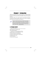
modifications of this manual occur, the updated version will be available on ASRock website without further notice. You may find the latest VGA cards and CPU support lists on ASRock website as well. ASRock website http://www.asrock.com 1.1 Package Contents ASRock 775i65G Motherboard (Micro ATX Form - ASRock 775i65G | User Manual - Page 6
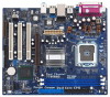
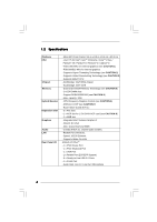
x AGP slot for 1.5V 8X/4X AGP card (see CAUTION 8) - 1 x AMR slot - Integrated Intel® Extreme Graphics 2 - DirectX 8.0 VGA - Max. shared memory 96MB - Cmedia 9761A 5.1 channel audio CODEC - Realtek PCI LAN 8101L - Speed: 10/100 Ethernet - Supports Wake-On-LAN ASRock I/O PlusTM - 1 x PS/2 Mouse Port - ASRock 775i65G | User Manual - Page 7
- Front panel audio connector - 2 x USB 2.0 headers (support 4 USB 2.0 ports; 2 of them are shared with USB4_5) (see CAUTION 9) - 4Mb AMI BIOS - AMI Legal BIOS - Supports "Plug and Play" - ACPI 1.1 Compliance Wake Up Events - Supports jumperfree - SMBIOS 2.3.1 Support - Drivers, Utilities, AntiVirus - ASRock 775i65G | User Manual - Page 8
1. FSB1066-CPU is supported only when you install AGP VGA card into AGP slot. Besides, if you use a FSB1066-CPU on this motherboard, please adopt a DDR400 CL2.5 memory module. 2. About the setting of "Hyper Threading Technology", please check page 25. 3. This motherboard supports Untied Overclocking - ASRock 775i65G | User Manual - Page 9
) Dual Core CPU Presler Conroe DDR1 (64/72 bit, 184-pin module) FSB800 Dual Channel FSB1066 29 28 27 26 25 24 23 Top: Line In Center: Line Out Bottom: Mic In Top: RJ-45 USB 2.0 T: USB0 B: USB1 USB 2.0 T: USB2 B: USB3 USB 2.0 1 T: USB4 B: USB5 IDE2 Intel 865G Chipset 775i65G USB4_5 Super - ASRock 775i65G | User Manual - Page 10
1.4 ASRock I/O PlusTM 1 11 10 9 1 Parallel Port 2 RJ-45 Port 3 Line In (Light Blue) 4 Line Out (Lime) 5 Microphone (Pink) 6 Shared USB 2.0 Ports (USB45) 2 3 4 5 8 7 6 7 USB 2.0 Ports (USB01) 8 USB 2.0 Ports (USB23) 9 VGA Port 10 PS/2 Keyboard Port (Purple) 11 PS/2 Mouse Port (Green) 10 - ASRock 775i65G | User Manual - Page 11
775i65G is a Micro ATX form factor (9.6" x 8.0", 24.4 x 20.3 cm) motherboard. Before you install the motherboard, study the configuration of your chassis to ensure that the motherboard fits into it. Make sure to unplug the power cord before installing or removing the motherboard. Failure - ASRock 775i65G | User Manual - Page 12
Rotate the load plate to fully open position at approximately 100 degrees. Step 2. Insert the 775-LAND CPU: Step 2-1. Hold the CPU by the edges where are marked with black lines. Step 2-2. Orient the CPU with IHS (Integrated Heat Sink) up. Locate Pin1 and the two orientation key notches. Pin1 - ASRock 775i65G | User Manual - Page 13
pressing on center of PnP cap to assist in removal. 1. It is recommended to use the cap tab to handle and avoid kicking off the PnP cap. 2. This cap must be placed if returning the motherboard for after service. Step 4. Close the socket: Step 4-1. Rotate the load plate onto the IHS. Step 4-2. While - ASRock 775i65G | User Manual - Page 14
are securely fastened and in good contact with each other. Then connect the CPU fan to the CPU_FAN connector (CPU_FAN1, see page 9, No. 6). For proper installation, please kindly refer to the instruction manuals of your CPU fan and heatsink. Below is an example to illustrate the installation of the - ASRock 775i65G | User Manual - Page 15
of Memory Modules (DIMM) This motherboard provides two 184-pin DDR (Double Data Rate) DIMM slots, and supports Dual Channel Memory Technology. For dual channel configuration, you always need to install two identical (the same brand, speed, size and chip-type) memory modules in the DDR DIMM slots to - ASRock 775i65G | User Manual - Page 16
2.6 Expansion Slots (PCI,AGP and AMR Slots) There are 3 PCI slots, 1 AGP slot, and 1 AMR slot on this motherboard. PCI slots: The PCI slots are used to install expansion cards that have the 32-bit PCI interface. AGP slot: The AGP slot is used to install a graphics card. The ASRock AGP slot has a - ASRock 775i65G | User Manual - Page 17
+5VSB or USB wake up events. Note: To select +5VSB, it requires 2 Amp and higher standby current provided by power supply. JR1(see p.9 No. 23) JL1(see p.9 No. 23) JR1 JL1 Note: If the jumpers JL1 and JR1 are short, both the front panel and the rear panel audio connectors can work. Clear CMOS - ASRock 775i65G | User Manual - Page 18
jumpers. Do NOT place jumper caps over these headers and connectors. Placing jumper caps over the headers and connectors will cause permanent damage of the motherboard use only one IDE device on this motherboard, please set the IDE device as "Master". Please refer to the instruction support SATA - ASRock 775i65G | User Manual - Page 19
this USB 2.0 header is available to support 2 additional USB 2.0 ports. Shared USB 2.0 Header (9-pin USB4_5) (see p.9 No. 29) 1 USB_PWR P-5 P+5 GND USB_PWR P-4 P+4 GND DUMMY This USB4_5 connector is shared with the USB 2.0 ports 4,5 on ASRock I/O PlusTM. When using the front panel USB ports by - ASRock 775i65G | User Manual - Page 20
USB. 2. HD (Azalia) audio front panel and AC'97 audio front panel have different pin-definition. Incorrect connection of the audio front panel and the front panel audio header may cause permanent damage to this motherboard to power up. This COM port header is used to support a COM port module. - ASRock 775i65G | User Manual - Page 21
the configuration details, please refer to the instruction on page 29. 2.10 Untied Overclocking Technology This motherboard supports Untied Overclocking Technology, which means during overclocking, FSB enjoys better margin due to fixed AGP / PCI bus. You may set "CPU Host Frequency" option of BIOS - ASRock 775i65G | User Manual - Page 22
use the BIOS SETUP UTILITY to configure your system. The BIOS FWH chip on the motherboard stores the BIOS SETUP UTILITY. You may run the BIOS SETUP UTILITY when you start and then back on. Because the BIOS software is constantly being updated, the following BIOS setup screens and descriptions are for - ASRock 775i65G | User Manual - Page 23
:00:09] [Fri 03/24/2006] BIOS Version : 775i65G BIOS P1.00 Processor Type : Intel (R) CPU 3.40 GHz (64bit supported) Processor Speed : 3400 Cache Size : 1024KB Microcode Update : F34/17 Total Memory DIMM 1 DIMM 2 : 512MB with 8MB shared memory Dual-Channel Memory Mode : 256MB/166MHz (DDR333 - ASRock 775i65G | User Manual - Page 24
will find an item Ratio CMOS Setting appears to allow you changing the ratio value of this motherboard. If it shows "Locked", then the item Ratio CMOS Setting will be hidden. If you use the ratio value to time the CPU frequency, it will be equal to the core speed of the installed processor. 24 - ASRock 775i65G | User Manual - Page 25
IA-32 Intel Architecture. An IA-32 processor with "No Execute (NX) Memory Protection" can prevent data pages from being used by malicious software to execute code. This option will be hidden if the current CPU does not support No-Excute Memory Protection. Hyper Threading Technology To enable this - ASRock 775i65G | User Manual - Page 26
Aperture Size [PCI / AGP] [64MB] OnBoard LAN OnBoard AC'97 Audio OnBoard MC'97 Modem selected, the motherboard will detect the memory module(s) inserted Use this item to adjust the means of memory accessing. Configuration options: [Auto], [2.5], [2], and [3]. DRAM RAS# Precharge This controls - ASRock 775i65G | User Manual - Page 27
range used for graphics memory. It is recommended to leave this field at the default value unless the installed AGP card's specifications requires other sizes. OnBoard LAN This allows you to enable or disable the "OnBoard LAN" feature. OnBoard AC'97 Audio Select [Auto], [Enabled] or [Disabled - ASRock 775i65G | User Manual - Page 28
3.3.3 ACPI Configuration BIOS SETUP UTILITY Advanced ACPI Configuration Suspend To RAM Ring-In Power On PCI Devices Power On PS / detect or disable the Sus pend-to-RAM feature. Select [Auto] will enable this feature if the system supports it. Ring-In Power On Use this item to enable or disable - ASRock 775i65G | User Manual - Page 29
, if it is set to [SATA + Sec IDE], then the primary IDE will not work. Because Intel® ICH5 south bridge only supports four IDE devices under legacy OS (Windows ME / 98SE), you have to choose either [Pri IDE + SATA] or [SATA + Sec IDE] when the installed SATA device is used with legacy OS. 29 - ASRock 775i65G | User Manual - Page 30
instruction, which can be applied to the configurations of "Primary IDE Slave", "Secondary IDE Master", "Secondary IDE Slave", "SATA1" and "SATA2" as well. BIOS Transfer :Hard Disk :ST340014A :40.0 GB :Supported :16Sectors :4 :MultiWord DMA-2 :Ultra DMA-5 :Supported [Auto] [Auto] [Auto] [Auto] [ - ASRock 775i65G | User Manual - Page 31
Reporting Technology) feature. Configuration options: [Disabled], [Auto], [Enabled]. 32-Bit Data Transfer Use this item to enable 32-bit access to maximize the IDE hard disk data transfer rate. 3.3.5 PCIPnP Configuration BIOS SETUP UTILITY Advanced PCI / PnP Configuration PCI Latency Timer PCI - ASRock 775i65G | User Manual - Page 32
v02.54 (C) Copyright 1985-2003, American Megatrends, Inc. 3.3.7 Super IO Configuration BIOS SETUP UTILITY Advanced Configure Super IO Chipset OnBoard Floppy Controller Serial Port Address Infrared Port Address Parallel Port Address Parallel Port Mode EPP Version ECP Mode DMA Channel Parallel - ASRock 775i65G | User Manual - Page 33
: [DMA0], [DMA1], and [DMA3]. Parallel Port IRQ Use this item to set the IRQ for the parallel port. Configuration options: [IRQ5] and [IRQ7]. 3.3.8 USB Configuration BIOS SETUP UTILITY Advanced USB Configuration USB Controller USB 2.0 Support Legacy USB Support [Enabled] [Enabled] [Disabled] To - ASRock 775i65G | User Manual - Page 34
you to monitor the status of the hardware on your system, including the parameters of the CPU temperature, motherboard temperature, CPU fan speed, chassis fan speed, and the critical voltage. BIOS SETUP UTILITY Main Advanced H/W Monitor Boot Security Exit Hardware Health Event Monitoring - ASRock 775i65G | User Manual - Page 35
F9 Load Defaults F10 Save and Exit ESC Exit v02.54 (C) Copyright 1985-2003, American Megatrends, Inc. 3.5.1 Boot Settings Configuration BIOS SETUP UTILITY Boot Boot Settings Configuration Boot From Network Bootup Num-Lock [Disabled] [On] To enable or disable the boot from network feature. +F1 - ASRock 775i65G | User Manual - Page 36
you may set or change the supervisor/user password for the system. For the user password, you may also clear it. BIOS SETUP UTILITY Main Advanced H/W Monitor Boot Security Exit Security Settings Supervisor Password : Not Installed User Password : Not Installed Change Supervisor Password - ASRock 775i65G | User Manual - Page 37
, Inc. Save Changes and Exit When you select this option, it will pop-out the following message, "Save configuration changes and exit setup?" Select [OK] to save the changes and exit the BIOS SETUP UTILITY. Discard Changes and Exit When you select this option, it will pop-out the following message - ASRock 775i65G | User Manual - Page 38
to your OS documentation for more information. 4.2 Support CD Information The Support CD that came with the motherboard contains necessary drivers and useful utilities that enhance the motherboard features. 4.2.1 Running The Support CD To begin using the support CD, insert the CD into your CD-ROM
-
 1
1 -
 2
2 -
 3
3 -
 4
4 -
 5
5 -
 6
6 -
 7
7 -
8
-
9
-
10
-
11
-
12
-
13
-
14
-
15
-
16
-
17
-
18
-
19
-
20
-
21
-
22
-
23
-
24
-
25
-
26
-
27
-
28
-
29
-
30
-
31
-
32
-
33
-
34
-
35
-
36
-
37
-
38
 |
 |

1
775i65G
User Manual
Version 2.4
Published November 2006
Copyright©2006 ASRock INC. All rights reserved.