ASRock 775i915P-SATA2 User Manual
ASRock 775i915P-SATA2 Manual
 |
View all ASRock 775i915P-SATA2 manuals
Add to My Manuals
Save this manual to your list of manuals |
ASRock 775i915P-SATA2 manual content summary:
- ASRock 775i915P-SATA2 | User Manual - Page 1
775i915P-SATA2 User Manual Version 1.0 Published August 2005 Copyright©2005 ASRock INC. All rights reserved. 1 - ASRock 775i915P-SATA2 | User Manual - Page 2
any form or by any means, except duplication of documentation by the purchaser for backup purpose, without written consent of ASRock Inc. Products and corporate names appearing in this manual may or may not be registered trademarks or copyrights of their respective companies, and are used only for - ASRock 775i915P-SATA2 | User Manual - Page 3
1 Introduction 5 1.1 Package Contents 5 1.2 Specifications 6 1.3 Supported PCI Express VGA Card List for AGI Express Slot 9 1.4 Motherboard Layout 10 1.5 ASRock 8CH I/O 11 2 Installation 12 2.1 Screw Holes 12 2.2 Pre-installation Precautions 12 2.3 CPU Installation 13 2.4 Installation of - ASRock 775i915P-SATA2 | User Manual - Page 4
40 3.6 Security Screen 40 3.7 Exit Screen 41 4 Software Support 42 4.1 Install Operating System 42 4.2 Support CD Information 42 4.2.1 Running Support CD 42 4.2.2 Drivers Menu 42 4.2.3 Utilities Menu 42 4.2.4 "LGA 775 CPU Installation Live Demo" Program .. 42 4.2.5 Contact Information 42 - ASRock 775i915P-SATA2 | User Manual - Page 5
and CPU support lists on ASRock website as well. ASRock website http://www.asrock.com 1.1 Package Contents ASRock 775i915P-SATA2 Motherboard (ATX Form Factor: 12.0-in x 9.6-in, 30.5 cm x 24.4 cm) ASRock 775i915P-SATA2 Quick Installation Guide ASRock 775i915P-SATA2 Support CD (including LGA 775 CPU - ASRock 775i915P-SATA2 | User Manual - Page 6
Slot Audio LAN Rear Panel I/O - ATX Form Factor: 12.0-in x 9.6-in, 30.5 cm x 24.4 cm - 775-Pin Socket supporting Intel® Pentium® 4 / Celeron® D processor (in 775-land LGA package) - FSB 800/533 MHz - Supports EM64T CPU - Supports Hyper-Threading Technology (see CAUTION 1) - Northbridge: Intel® 915P - ASRock 775i915P-SATA2 | User Manual - Page 7
in header - Front panel audio connector - 2 x USB 2.0 headers (support 4 USB 2.0 ports) (see CAUTION 7) - 2Mb AMI BIOS - AMI Legal BIOS - Supports "Plug and Play" - ACPI 1.1 Compliance Wake Up Events - Supports jumperfree - Drivers, Utilities, AntiVirus Software - CPU Temperature Sensing - Chassis - ASRock 775i915P-SATA2 | User Manual - Page 8
. For audio output, this motherboard supports 2-channel, 4-channel, 6-channel, and 8-channel modes. Please check the table on page 11 for proper connection. 7. Power Management for USB 2.0 works fine under Microsoft® Windows® XP SP1 / 2000 SP4. 8. Because of Intel 915P chipset limitation, Windows 98 - ASRock 775i915P-SATA2 | User Manual - Page 9
1.3 Supported PCI Express VGA Card List for AGI Express Slot (for Windows 2000/Windows XP) Graphics Chip Vendor For the latest updates of the supported PCI Express VGA card list for AGI Express slot, please visit our website for details. ASRock website: http://www.asrock.com/support/index.htm Note. - ASRock 775i915P-SATA2 | User Manual - Page 10
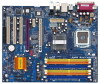
1.4 Motherboard Layout 12 PS2 Mouse 1 PS2_USB_PWR1 ATX12V1 34 5 6 78 24.4cm (9.6 in) DDR400/DDRII533 775i915P-SATA2 CPU_FAN1 RoHS Dual Channel PARALLEL PORT PS2 Keyboard COM1 DDR DIMMII3 (64/72 bit, 240-pin module) DDR DIMMII4 (64/72 bit, 240-pin module) DDR DIMM2 ( - ASRock 775i915P-SATA2 | User Manual - Page 11
1.5 ASRock 8CH I/O 1 13 12 11 2 3 6 4 7 5 8 10 9 1 Parallel Port 2 RJ-45 Port 3 table below for connection details in accordance with the type of speaker you use. TABLE for Audio Output Connection Audio Output Channels Front Speaker Rear Speaker Central / Bass (No. 7) (No. 4) (No. - ASRock 775i915P-SATA2 | User Manual - Page 12
775i915P-SATA2 is an ATX form factor (12.0" x 9.6", 30.5 x 24.4 cm) motherboard. Before you install the motherboard, study the configuration of your chassis to ensure that the motherboard fits into it. Make sure to unplug the power cord before installing or removing the motherboard. Failure - ASRock 775i915P-SATA2 | User Manual - Page 13
the installation of Intel 775-LAND CPU, please follow the steps below. 775-Pin Socket Overview Before you insert the 775-LAND CPU into the socket, please check if the CPU surface is unclean or if there is any bent pin on the socket. Do not force to insert the CPU into the socket if above situation - ASRock 775i915P-SATA2 | User Manual - Page 14
to use the cap tab to handle and avoid kicking off the PnP cap. 2. This cap must be placed if returning the motherboard for after service. Step 4. Close the socket: Step 4-1. Rotate the load plate onto the IHS. Step 4-2. While pressing down lightly on load plate, engage the load lever. Step - ASRock 775i915P-SATA2 | User Manual - Page 15
Heatsink This motherboard is equipped with 775-Pin socket that supports Intel 775-LAND CPU. Please adopt the type of heatsink and cooling fan compliant with Intel 775-LAND CPU to dissipate heat. Before you installed the heatsink, you need to spray thermal interface material between the CPU and the - ASRock 775i915P-SATA2 | User Manual - Page 16
2.5 Installation of Memory Modules (DIMM) 775i915P-SATA2 motherboard provides four 240-pin DDRII (Double Data Rate) DIMM slots, two 184-pin DDR (Double Data Rate) DIMM slots, and supports Dual Channel DDR/DDRII Memory Technology. For dual channel configuration, you always need to install identical ( - ASRock 775i915P-SATA2 | User Manual - Page 17
matches the break on the slot. notch break notch break The DIMM only fits in one correct orientation. It will cause permanent damage to the motherboard and the DIMM if you force the DIMM into the slot at incorrect orientation. Step 3. Firmly insert the DIMM into the slot until the retaining - ASRock 775i915P-SATA2 | User Manual - Page 18
PCI Express slots, and 1 AGI Express slot on this motherboard. PCI slots: PCI slots are used to install expansion PCI Express cards, such as Gigabit LAN card, SATA2 card, etc. Please check the jumper set tings Express VGA cards, please refer to the "Supported PCI Express VGA Card List for AGI - ASRock 775i915P-SATA2 | User Manual - Page 19
2.7 Dual Graphics Feature This motherboard supports Dual Graphics Technology. When installing the add-on VGA cards to this motherboard, you are allowed choosing two different ways to decide the function of PCIE2 slot (PCIE x 1), AGI Express slot, and SATA II. The default value of - ASRock 775i915P-SATA2 | User Manual - Page 20
2.8 PCIE VGA Card Driver Installation Guide For Windows 98 SE / ME If your system is Windows 98 / ME and want to install PCIE VGA card driver. Please follow the below steps for proper driver installation. 1. Click "My Computer" on your desktop, and right-click "Properties". 2. Select "Device Manager - ASRock 775i915P-SATA2 | User Manual - Page 21
2.9 Surround Display Feature This motherboard supports Surround Display upgrade. With the external add-on JR1 JL1 Note: If the jumpers JL1 and JR1 are short, both the front panel and the rear panel audio connectors can work. Clear CMOS (CLRCMOS1, 2-pin jumper) (see p.10 No. 25) 2-pin jumper Note - ASRock 775i915P-SATA2 | User Manual - Page 22
black end to the motherboard to the IDE devices 80-conductor ATA 66/100 cable Note: Please refer to the instruction of your IDE device vendor p.10 No. 11) SATA1 SATA3 SATA II_1 SATA2 SATA4 These four Serial ATA (SATA) connectors support SATA data cables for internal storage devices. The - ASRock 775i915P-SATA2 | User Manual - Page 23
on the I/O panel are not sufficient, this USB 2.0 header is available to support 2 additional USB 2.0 ports. USB 2.0 Header (9-pin USB45) (see p. +5VSB DUMMY 1 GND IRRX Internal Audio Connectors (4-pin CD1) (CD1: see p.10 No. 37) CD-R GND GND CD-L CD1 ASRock 8CH I/O accommodates 4 default USB - ASRock 775i915P-SATA2 | User Manual - Page 24
Speaker Header (4-pin SPEAKER 1) (see p.10 No. 21) Chassis Fan Connector (3-pin CHA_FAN1) (see p.10 No. 20) CPU Fan Connector (4-pin CPU_FAN1) (see p.10 No. 5) ATX Power Connector (20-pin ATXPWR1) (see p.10 No. 38) when two graphics cards are plugged to this motherboard at the same time. 24 - ASRock 775i915P-SATA2 | User Manual - Page 25
guide. Some default setting of SATAII hard disk drives may not be at SATAII mode , which operate with the best performance. In order to enable SATAII function, please follow the below instruction for details: http://www.hitachigst.com/hdd/support/download.htm The above examples are just for your - ASRock 775i915P-SATA2 | User Manual - Page 26
hard disk. 2.14 Hot Plug Function for SATAII HDDs 775i915P-SATA2 motherboard supports Hot Plug function for SATAII Devices. (For this motherboard, only JMicron JMB360 chipset provides Hot Plug function support; Intel ICH6 chipset does not support Hot Plug function.) NOTE What is Hot Plug Function - ASRock 775i915P-SATA2 | User Manual - Page 27
the BIOS SETUP UTILITY to configure your system. The BIOS FWH chip on the motherboard stores the BIOS SETUP UTILITY. You may run the BIOS SETUP off and then back on. Because the BIOS software is constantly being updated, the following BIOS setup screens and descriptions are for reference purpose - ASRock 775i915P-SATA2 | User Manual - Page 28
Exit System Overview System Time System Date [14:00:09] [Fri 09/02/2005] BIOS Version : 775i915P-SATA2 BIOS P1.00 Processor Type : Intel (R) CPU 3.40 GHz (64bit supported) Processor Speed : 3400 MHz Microcode Update : F34/14 Cache Size : 1024KB Total Memory DDR1 DDR2 : 512MB Dual-Channel - ASRock 775i915P-SATA2 | User Manual - Page 29
Defaults Save and Exit Exit v02.54 (C) Copyright 1985-2005, American Megatrends, Inc. CPU Host Frequency While entering setup, BIOS auto detects the present CPU host frequency of this motherboard. The actual CPU host frequency will show in the following item. Boot Failure Guard Enable or disable - ASRock 775i915P-SATA2 | User Manual - Page 30
option will be hidden if the current CPU does not support No-Excute Memory Protection. Enhance Halt State All processors support the Halt State (C1). The C1 state is supported through the native processor instructions HLT and MWAIT and requires no hardware support from the chipset. In the C1 power - ASRock 775i915P-SATA2 | User Manual - Page 31
BIOS SETUP UTILITY Advanced Chipset Configuration DRAM Frequency [Auto] Flexibility Option [Disabled] Configure DRAM Timing by SPD [Enabled] DRAM CAS# Latency [Auto] Boot Graphic Adapter Priority [PCIE/PCI] OnBoard LAN OnBoard AC'97 Audio is selected, the motherboard will detect the memory - ASRock 775i915P-SATA2 | User Manual - Page 32
Audio feature. VCCM Use this to select VCCM. Configuration options: [High], [Low],and [Auto]. The default value of this feature is [Auto]. VDDQ Use this to select VDDQ. Configuration options: [High], and [Low]. The default value of this feature is [Low]. 3.3.3 ACPI Configuration BIOS system supports - ASRock 775i915P-SATA2 | User Manual - Page 33
BIOS SETUP UTILITY Advanced IDE Configuration ATA/IDE Configuration OnBoard SATAII Controller SATAII Operation Mode SATA1 SATA2 SATA1, SATA3 will not work. Because Intel® ICH6 south bridge only supports four IDE devices under legacy OS (Windows ME / 98SE), you have to choose [SATA 1, SATA 2, SATA - ASRock 775i915P-SATA2 | User Manual - Page 34
Master" as the example in the following instruction. BIOS SETUP UTILITY Advanced Primary IDE Master Device Vendor Disk :ST340014A :40.0 GB :Supported :16Sectors :4 :MultiWord DMA-2 :Ultra DMA-5 :Supported [Auto] [Auto] [Auto] Windows; for Netware and UNIX user, select [Disabled] to disable the LBA - ASRock 775i915P-SATA2 | User Manual - Page 35
32-Bit Data Transfer Use this item to enable 32-bit access to maximize the IDE hard disk data transfer rate. 3.3.5 PCIPnP Configuration BIOS SETUP UTILITY Advanced Advanced PCI / PnP Settings WARNING: Setting wrong values in below actions may cause system to malfunction. PCI Latency Timer PCI - ASRock 775i915P-SATA2 | User Manual - Page 36
Channel Parallel Port IRQ OnBoard Game Port OnBoard MIDI Port [Enabled] [3F8 / IRQ4] [Disabled] [378] [ECP + EPP] [1.9] [DMA3] [IRQ7] [Enabled] [Disabled] Allow BIOS to Enable or Disable Floppy Controller. +F1 F9 F10 ESC Select Screen Select Item Change Option General Help Load Defaults Save and - ASRock 775i915P-SATA2 | User Manual - Page 37
Parallel Port Address Use this item to set the address for the onboard parallel port or disable it. Configuration options: [Disabled], [378], and [278]. Parallel Port Mode Use this item to set the operation mode of the parallel port. The default value is [ECP+EPP]. If this option is set to [ECP+EPP - ASRock 775i915P-SATA2 | User Manual - Page 38
controller. USB 2.0 Support Use this item to enable or disable the USB 2.0 support. Legacy USB Support Use this item to enable or disable the support to emulate legacy of the CPU temperature, motherboard temperature, CPU fan speed, chassis fan speed, and the critical voltage. BIOS SETUP UTILITY - ASRock 775i915P-SATA2 | User Manual - Page 39
speed. The default value is [90%]. Configuration options: [90%] and [85%]. The CPU fan speed will be controlled at the rate of 90% or 85%. 3.5 Boot Screen In configure the boot settings and the boot priority. Main Advanced BIOS SETUP UTILITY H/W Monitor Boot Security Exit Boot Settings Boot - ASRock 775i915P-SATA2 | User Manual - Page 40
you may set or change the supervisor/user password for the system. For the user password, you may also clear it. BIOS SETUP UTILITY Main Advanced H/W Monitor Boot Security Exit Security Settings Supervisor Password : Not Installed User Password : Not Installed Change Supervisor Password - ASRock 775i915P-SATA2 | User Manual - Page 41
and exit setup?" Select [OK] to save the changes and exit the BIOS SETUP UTILITY. Discard Changes and Exit When you select this option, it message, "Discard changes and exit setup?" Select [OK] to exit the BIOS SETUP UTILITY without saving any changes. Discard Changes When you select this option - ASRock 775i915P-SATA2 | User Manual - Page 42
This motherboard is equipped with Intel LGA 775 socket, which is a new CPU socket interface that Intel has released. Since it has several tiny pins, whcih are easily to be damaged by improper handling, ASRock sincerely presents you a clear installation guide through this "LGA 775 CPU Installation
-
 1
1 -
 2
2 -
 3
3 -
 4
4 -
 5
5 -
 6
6 -
 7
7 -
8
-
9
-
10
-
11
-
12
-
13
-
14
-
15
-
16
-
17
-
18
-
19
-
20
-
21
-
22
-
23
-
24
-
25
-
26
-
27
-
28
-
29
-
30
-
31
-
32
-
33
-
34
-
35
-
36
-
37
-
38
-
39
-
40
-
41
-
42
 |
 |

1
775i915P-SATA2
User Manual
Version 1.0
Published August 2005
Copyright©2005 ASRock INC. All rights reserved.