ASRock 790GX Pro User Manual
ASRock 790GX Pro Manual
 |
View all ASRock 790GX Pro manuals
Add to My Manuals
Save this manual to your list of manuals |
ASRock 790GX Pro manual content summary:
- ASRock 790GX Pro | User Manual - Page 1
790GX Pro User Manual Version 1.0 Published May 2010 Copyright©2010 ASRock INC. All rights reserved. 1 - ASRock 790GX Pro | User Manual - Page 2
purpose, without written consent of ASRock Inc. Products and corporate names appearing in this manual may or may not be registered trademarks or copyrights of their CALIFORNIA, USA ONLY The Lithium battery adopted on this motherboard contains Perchlorate, a toxic substance controlled in Perchlorate - ASRock 790GX Pro | User Manual - Page 3
Motherboard Layout 11 1.4 I/O Panel 12 2 . Installation 13 Pre-installation Precautions 13 2.1 CPU Installation 14 2.2 Installation of CPU 30 2.12 SATA / SATAII HDD Hot Plug Feature and Operation Guide ...... 31 2.13 Driver Installation Guide 33 2.14 Installing Windows® 7 / 7 64-bit / VistaTM - ASRock 790GX Pro | User Manual - Page 4
BIOS Menu Bar 38 3.1.2 Navigation Keys 39 3.2 Main Screen 39 3.3 OC Tweaker Screen 40 3.4 Advanced Screen 48 3.4.1 CPU Screen 61 4 . Software Support 62 4.1 Install Operating System 62 4.2 Support CD Information 62 4.2.1 Running Support CD 62 4.2.2 Drivers Menu 62 4.2.3 Utilities Menu - ASRock 790GX Pro | User Manual - Page 5
information about the model you are using. www.asrock.com/support/index.asp 1.1 Package Contents ASRock 790GX Pro Motherboard (ATX Form Factor: 12.0-in x 8.8-in, 30.5 cm x 22.4 cm) ASRock 790GX Pro Quick Installation Guide ASRock 790GX Pro Support CD 2 x Serial ATA (SATA) Data Cables (Optional - ASRock 790GX Pro | User Manual - Page 6
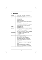
Expansion Slot Graphics - ATX Form Factor: 12.0-in x 8.8-in, 30.5 cm x 22.4 cm - Solid Capacitor for CPU power - Support for Socket AM3 processors: AMD PhenomTM II X6 / X4 / X3 / X2 (except 920 / 940) / Athlon II X4 / X3 / X2 / Sempron processors - Six-Core CPU Ready - Supports CPU up to 140W - ASRock 790GX Pro | User Manual - Page 7
header - 1 x Power LED header - CPU/Chassis/NB/Power FAN connector - 24 pin ATX power connector - 8 pin 12V power connector - CD in header - Front panel audio connector - 3 x USB 2.0 headers (support 6 USB 2.0 ports) - 8Mb AMI BIOS - AMI Legal BIOS - Supports "Plug and Play" - ACPI 1.1 Compliance - ASRock 790GX Pro | User Manual - Page 8
Support CD - Drivers, Utilities, AntiVirus Software (Trial Version), AMD OverDriveTM Utility, AMD Live! Explorer, AMD Fusion, ASRock Software Suite (CyberLink DVD Suite - OEM and Trial; Creative Sound Blaster X-Fi MB - Trial) Unique Feature - ASRock OC Tuner (see CAUTION 8) - Intelligent - ASRock 790GX Pro | User Manual - Page 9
1800/1600MHz memory speed is supported depends on the AM3 CPU you adopt. If you want to adopt DDR3 1800/1600 memory module on this motherboard, please refer to the memory support list on our website for the compatible memory modules. ASRock website http://www.asrock.com 4. Due to the operating - ASRock 790GX Pro | User Manual - Page 10
ROM. This convenient BIOS update tool allows you to update system BIOS without entering operating systems first like MS-DOS or Windows®. With this utility, you can press key during the POST or press key to BIOS setup menu to access ASRock Instant Flash. Just launch this tool and save the - ASRock 790GX Pro | User Manual - Page 11
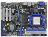
RJ-45 LAN Top: CTR BASS Center: REAR SPK FRONT Top: LINE IN Center: PWR_FAN1 PCIE1 LAN PHY AMD 790GX Chipset Support 6-Core CPU PCIE2 PCI Express 2.0 CMOS BATTERY NB_FAN1 IDE1 Super I/O AUDIO CODEC HDMI_SPDIF1 1 CD1 1 HD_AUDIO1 PCIE3 790GX Pro Hybrid CrossFire PCI1 AMD SB750 Chipset - ASRock 790GX Pro | User Manual - Page 12
2 VGA/D-Sub Port 3 USB 2.0 Ports (USB45) * 4 LAN RJ-45 Port 5 Central / Bass (Orange) 6 Rear Speaker (Black) 7 Optical SPDIF Out Port 8 Line In (Light Blue) 13 audio header. After restarting your computer, you will find "Mixer" tool on your system. Please select "Mixer ToolBox" , click "Enable - ASRock 790GX Pro | User Manual - Page 13
, peripherals, and/or components. 1. Unplug the power cord from the wall socket before touching any component. 2. To avoid damaging the motherboard components due to static electricity, NEVER place your motherboard directly on the carpet or the like. Also remember to use a grounded wrist strap - ASRock 790GX Pro | User Manual - Page 14
Socker Corner Small Triangle STEP 2 / STEP 3: Match The CPU Golden Triangle To The Socket Corner Small Triangle STEP 4: Push Down And Lock The Socket Lever 2.2 Installation of CPU Fan and Heatsink After you install the CPU into this motherboard, it is necessary to install a larger heatsink and - ASRock 790GX Pro | User Manual - Page 15
2.3 Installation of Memory Modules (DIMM) This motherboard provides four 240-pin DDR3 (Double Data Rate 3) DIMM slots, and supports Dual Channel Memory Technology. For dual channel configuration, you always need to install identical (the same brand, speed, size and chip-type) DDR3 DIMM pair - ASRock 790GX Pro | User Manual - Page 16
adding or removing DIMMs or the system components. Step 1. Step 2. Unlock a DIMM slot by pressing the retaining clips outward. Align a DIMM only fits in one correct orientation. It will cause permanent damage to the motherboard and the DIMM if you force the DIMM into the slot at incorrect - ASRock 790GX Pro | User Manual - Page 17
the expansion card and make necessary hardware settings for the card before you start the installation. Step 2. Remove the system unit cover (if your motherboard is already installed in a chassis). Step 3. Remove the bracket facing the slot that you intend to use. Keep the screws for later use. Step - ASRock 790GX Pro | User Manual - Page 18
after your system boots. If you haven't installed onboard VGA driver yet, please install onboard VGA driver from our support CD to your system and restart your computer. Then you can start to use dual monitor function on this motherboard. 1. DVI-D and HDMI ports cannot function at the same time - ASRock 790GX Pro | User Manual - Page 19
memory. If you do not adjust the BIOS setup, the default value of "Share Memory", [Auto], will disable VGA/D-Sub function when the add-on VGA card is inserted to this motherboard. 4. Install the onboard VGA driver and the add-on PCI Express VGA card driver to your system. If you have installed - ASRock 790GX Pro | User Manual - Page 20
supported on this motherboard. To use HDCP function with this motherboard, you need to adopt the monitor that supports HDCP function as well. Therefore, you can enjoy the superior display quality with high-definition HDCP encryption contents. Please refer to below instruction . Products compatible - ASRock 790GX Pro | User Manual - Page 21
2.6 ATITM Hybrid CrossFireXTM Operation Guide This motherboard supports ATITM Hybrid CrossFireXTM feature. ATITM Hybrid CrossFireXTM brings multi-GPU performance capabilities by enabling an AMD 790GX integrated graphics processor and a discrete graphics processor to operate simultaneously with - ASRock 790GX Pro | User Manual - Page 22
. Step 10. Reboot your system. Then you can freely enjoy the benefit of HybridTM CrossFireXTM feature. * Hybrid CrossFireXTM appearing here is a registered trademark of ATITM Technologies Inc., and is used only for identification or explanation and to the owners' benefit, without intent to infringe - ASRock 790GX Pro | User Manual - Page 23
short pin2 and pin3 on CLRCMOS1 for 5 seconds. However, please do not clear the CMOS right after you update the BIOS. If you need to clear the CMOS when you just finish updating the BIOS, you must boot up the system first, and then shut it down before you do the clear-CMOS action - ASRock 790GX Pro | User Manual - Page 24
blue end to the motherboard connect the black end to the IDE devices 80-conductor ATA 66/100/133 cable Note: Please refer to the instruction of your IDE ) Data Cable (Optional) These five Serial ATAII (SATAII) connectors support SATAII or SATA hard disk for internal storage devices. The current - ASRock 790GX Pro | User Manual - Page 25
2.0 headers on this motherboard. Each USB 2.0 header can support two USB 2.0 ports. This header supports an optional wireless transmitting supports Jack Sensing, but the panel wire on the chassis must support HDA to function correctly. Please follow the instruction in our manual and chassis manual - ASRock 790GX Pro | User Manual - Page 26
D. MIC_RET and OUT_RET are for HD audio panel only. You don't need to connect them for AC'97 audio panel. E. To activate the front mic. For Windows® XP / XP 64-bit OS: Select "Mixer". Select "Recorder". Then click "FrontMic". For Windows® 7 / 7 64-bit / VistaTM / VistaTM 64-bit OS: Go to the " - ASRock 790GX Pro | User Manual - Page 27
fan (Quiet Fan) support, the 3-Pin CPU fan still can work successfully even without the fan speed control function. If you plan to connect the 3-Pin CPU fan to the CPU fan connector on this motherboard, please connect it to Pin 1-3. Pin 1-3 Connected 3-Pin Fan Installation ATX Power Connector (24 - ASRock 790GX Pro | User Manual - Page 28
HDMI_SPDIF Header (2-pin HDMI_SPDIF1) (see p.11 No. 33) 1 GND SPDIFOUT HDMI_SPDIF header, providing SPDIF audio output to HDMI VGA card, allows the system to connect HDMI Digital TV/ projector/LCD devices. Please connect the HDMI_SPDIF connector of HDMI VGA card to this header. 28 - ASRock 790GX Pro | User Manual - Page 29
Please use the Feature Tool, a DOS-bootable tool, for changing various ATA features. Please visit HITACHI's website for details: http://www.hitachigst.com/hdd/support/download.htm The above examples are just for your reference. For different SATAII hard disk products of different vendors, the - ASRock 790GX Pro | User Manual - Page 30
AMD SB750 south bridge chipset that supports Serial ATA (SATA) / Serial ATAII (SATAII) hard disks and RAID (RAID 0, RAID 1, RAID 5, RAID 10 and JBOD) functions. You may install SATA / SATAII hard disks on this motherboard for internal storage devices. This section will guide you to install the SATA - ASRock 790GX Pro | User Manual - Page 31
SATA / SATAII Hot Plug support information of our motherboard is indicated in the product spec on our website: www.asrock.com 2. Make sure your SATA / SATAII HDD can support Hot Plug function from your dealer or HDD user manual. The SATA / SATAII HDD, which cannot support Hot Plug function, will be - ASRock 790GX Pro | User Manual - Page 32
cable to (White) to the power supply 1x4-pin cable. the motherboard's SATAII connector. SATA power cable 1x4-pin power connector (White) Step attention, before you process the Hot Unplug: Please do follow below instruction sequence to process the Hot Unplug, improper procedure will cause the SATA - ASRock 790GX Pro | User Manual - Page 33
functions, please follow below steps. STEP 1: Set up BIOS. A. Enter BIOS SETUP UTILITY Advanced screen Storage Configuration. B. Set the "SATA Operation Mode" option to [RAID]. STEP 2: Make a SATA / SATAII Driver Diskette. A. Insert the ASRock Support CD into your optical drive to boot your - ASRock 790GX Pro | User Manual - Page 34
configure RAID function, you need to check the RAID installation guide in the Support CD for proper configuration. Please refer to the BIOS RAID installation guide part of the document in the following path in the Support CD: .. \ RAID Installation Guide STEP 4: Install Windows® XP / XP 64-bit OS on - ASRock 790GX Pro | User Manual - Page 35
still need to set up "SATA Operation Mode" to [RAID] in BIOS first. Then, please set the RAID configuration by using the Windows RAID installation guide in the following path in the Support CD: .. \ RAID Installation Guide NOTE2. Currently, if you install Windows® 7 / 7 64-bit / VistaTM / VistaTM 64 - ASRock 790GX Pro | User Manual - Page 36
functions, please follow below steps. Using SATA / SATAII HDDs with NCQ and Hot Plug functions (AHCI mode) STEP 1: Set Up BIOS. A. Enter BIOS SETUP UTILITY Advanced screen Storage Configuration. B. Set the "SATA Operation Mode" option to [AHCI]. STEP 2: Install Windows® 7 / 7 64-bit / VistaTM - ASRock 790GX Pro | User Manual - Page 37
This motherboard supports Untied Overclocking Technology, which means during overclocking, FSB enjoys better margin due to fixed PCI / PCIE buses. Before you enable Untied Overclocking function, please enter "Overclock Mode" option of BIOS setup to set the selection from [Auto] to [CPU, PCIE - ASRock 790GX Pro | User Manual - Page 38
motherboard stores the BIOS SETUP UTILITY. You may run the BIOS SETUP UTILITY when you start up the computer. Please press or during the Power-On-Self-Test (POST) to enter the BIOS on. Because the BIOS software is constantly being updated, the following BIOS setup screens and descriptions - ASRock 790GX Pro | User Manual - Page 39
Exit System Overview System Time System Date [17:00:09] [Wed 05/25/2010] BIOS Version : 790GX Pro P1.00 Processor Type : AMD Athlon(tm) II X4 620 Processor (64bit) Processor Speed : 2700MHz Microcode Update : 100F41/1000086 L1 Cache Size : 512KB L2 Cache Size : 2048KB L3 Cache Size : 6144KB - ASRock 790GX Pro | User Manual - Page 40
Core Technology AMD IO C-State Support Processor Maximum Frequency North Bridge Maximum Frequency [Auto] [200] [100] [Auto] [Enabled] [3] [Disabled] [Disabled] [Enabled] [Enabled] x10.5 2100 MHZ x9.0 1800 MHz Overclocking may cause damage to your CPU and motherboard. It should be done at your - ASRock 790GX Pro | User Manual - Page 41
item is set to [Auto] by default. If it is set to [Manual], you may adjust the value of Processor Frequency and Processor Voltage. However, it is recommended to keep the default value for system stability. BIOS SETUP UTILITY Main OC Tweaker Advanced H/W Monitor Boot Security Exit Load Optimized - ASRock 790GX Pro | User Manual - Page 42
Frequency Multiplier For safety and system stability, it is not recommended to adjust the value of this item. CPU Voltage It allows you to adjust the value of CPU voltage. However, for safety and system stability, it is not recommended to adjust the value of this item. NB Frequency Multiplier For - ASRock 790GX Pro | User Manual - Page 43
Memory Timing BIOS SETUP UTILITY OC Tweaker Memory Configuration Memory Controller Mode Power Down Enable Bank Interleaving Channel Interleaving CAS Latency (CL) 9 TRCD 12 TRP 12 TRAS 30 - ASRock 790GX Pro | User Manual - Page 44
TRRD Use this to adjust TRRD values. Configuration options: [Auto], [4CLK] to [7CLK]. The default value is [Auto]. TWTR Use this to adjust TWTR values. Configuration options: [Auto], [4CLK] to [7CLK]. The default value is [Auto]. TWR Use this to adjust TWR values. Configuration options: [Auto], [ - ASRock 790GX Pro | User Manual - Page 45
CHA ADDR/CMD Setup Use this to adjust values for CHA ADDR/CMD Setup feature. Configuration options: [Auto], [1/2CLK] and [1CLK]. The default value is [Auto]. CHA CS/ODT Delay Use this to adjust values for CHA CS/ODT Delay feature. Configuration options: [Auto], [No Delay], [1/64CLK] to [31/64CLK]. - ASRock 790GX Pro | User Manual - Page 46
adjust values for CHB DQS Drive. Configuration options: [Auto], [0.75x], [1.00x], [1.25x] and [1.50x]. The default value is [Auto]. CHB Processor ODT Use this to adjust values for CHB Processor ODT. Configuration options: [Auto], [240 ohms], [120 ohms] and [60 ohms]. The default value is [Auto]. 46 - ASRock 790GX Pro | User Manual - Page 47
Chipset Settings Onboard GPU Clock Override This allows you to enable or disable the Onboard GPU Clock Override feature. Onboard GPU Clock This option only appears when you enable "Onboard GPU Clock Override". The default value is [700]. mGPU Voltage Use this to select mGPU voltage. Configuration - ASRock 790GX Pro | User Manual - Page 48
Setting wrong values in this section may cause the system to malfunction. ASRock Instant Flash ASRock Instant Flash is a BIOS flash utility embedded in Flash ROM. This convenient BIOS update tool allows you to update system BIOS without entering operating systems first like MS-DOS or Windows®. Just - ASRock 790GX Pro | User Manual - Page 49
the native processor instructions HLT and MWAIT and requires no hardware support from the chipset. In the C1 power state, the processor maintains the context of the system caches. L3 Cache Allocation The default value is [Auto]. Configuration options: [Auto], [BSP Only] and [All Cores]. CPU Thermal - ASRock 790GX Pro | User Manual - Page 50
3.4.2 Chipset Configuration BIOS SETUP UTILITY Advanced Chipset Settings Onboard HD Audio Front Panel Onboard Lan Energy Efficient Ethernet Dr. LAN Link speed : 10Mbps Primary Graphics Adapter Internal Graphics - ASRock 790GX Pro | User Manual - Page 51
Onboard HDMI HD Audio This allows you to enable or disable the onboard HDMI HD Audio in AMD 790GX. Surround View This allows you to enable or disable the Surround View feature or Hybrid CrossFireXTM feature. 51 - ASRock 790GX Pro | User Manual - Page 52
3.4.3 ACPI Configuration BIOS SETUP UTILITY Advanced ACPI Settings Suspend To RAM Check Ready Bit Away Mode Support Restore on AC / Power Loss Ring-In Power On PCI Devices Power On PS set this option to [Enabled] if you plan to use this motherboard to submit Windows® VistaTM certification. 52 - ASRock 790GX Pro | User Manual - Page 53
for the device that you specify. We will use the "IDE1 Master" as the example in the following instruction, which can be applied to the configurations of "IDE1 Slave" as well. BIOS SETUP UTILITY Advanced Primary IDE Master Device Vendor Size LBA Mode Block Mode PIO Mode Async DMA Ultra DMA - ASRock 790GX Pro | User Manual - Page 54
to automatically detect the hard disk drive. After selecting the hard disk information into BIOS, use a disk utility, such as FDISK, to partition and format the new this item to select the LBA/Large mode for a hard disk > 512 MB under DOS and Windows; for Netware and UNIX user, select [Disabled] to - ASRock 790GX Pro | User Manual - Page 55
BIOS SETUP UTILITY Advanced Advanced PCI / PnP Settings PCI Latency Timer PCI IDE BusMaster [32] [Enabled] Value in units of PCI clocks for PCI device latency timer register type of your floppy drive. BIOS SETUP UTILITY Advanced Floppy Configuration Floppy A [1.44 MB 312"] Select the type of - ASRock 790GX Pro | User Manual - Page 56
Configure Super IO Chipset OnBoard Floppy Controller Serial Port Address Infrared Port Address PS/2 Port Type [Enabled] [3F8 / IRQ4] [Disabled] [Auto] Allow BIOS to Enable or Disable Floppy Controller. +F1 F9 F10 ESC Select Screen Select Item Change Option General Help Load Defaults Save and - ASRock 790GX Pro | User Manual - Page 57
Use this item to enable or disable the USB 2.0 support. Legacy USB Support Use this option to select legacy support for USB devices. There are four configuration options: [Enabled], [Auto], [Disabled] and [BIOS Setup Only]. The default value is [Enabled]. Please refer to below descriptions for - ASRock 790GX Pro | User Manual - Page 58
to monitor the status of the hardware on your system, including the parameters of the CPU temperature, motherboard temperature, CPU fan speed, chassis fan speed, and the critical voltage. BIOS SETUP UTILITY Main OC Tweaker Advanced H/W Monitor Boot Security Exit Hardware Health Event Monitoring - ASRock 790GX Pro | User Manual - Page 59
F1 General Help F9 Load Defaults F10 Save and Exit ESC Exit v02.54 (C) Copyright 1985-2005, American Megatrends, Inc. 3.6.1 Boot Settings Configuration BIOS SETUP UTILITY Boot Boot Settings Configuration Full Screen Logo AddOn ROM Display Boot Logo Boot From Onboard LAN Bootup Num-Lock [Enabled - ASRock 790GX Pro | User Manual - Page 60
option "Full Screen Logo". Configuration options: [Auto], [EuP], [Scenery] and [ASRock]. The default value is [Auto]. Boot From Onboard LAN Use this item to enable system. For the user password, you may also clear it. BIOS SETUP UTILITY Main OC Tweaker Advanced H/W Monitor Boot Security Exit - ASRock 790GX Pro | User Manual - Page 61
. Discard Changes When you select this option, it will pop-out the following message, "Discard changes?" Select [OK] to discard all changes. Load BIOS Defaults Load BIOS default values for all the setup questions. F9 key can be used for this operation. Load Performance Setup Default (IDE/SATA) This - ASRock 790GX Pro | User Manual - Page 62
install the necessary drivers to activate the devices. 4.2.3 Utilities Menu The Utilities Menu shows the applications software that the motherboard supports. Click on a specific item then follow the installation wizard to install it. 4.2.4 Contact Information If you need to contact ASRock or want to
-
 1
1 -
 2
2 -
 3
3 -
 4
4 -
 5
5 -
 6
6 -
 7
7 -
8
-
9
-
10
-
11
-
12
-
13
-
14
-
15
-
16
-
17
-
18
-
19
-
20
-
21
-
22
-
23
-
24
-
25
-
26
-
27
-
28
-
29
-
30
-
31
-
32
-
33
-
34
-
35
-
36
-
37
-
38
-
39
-
40
-
41
-
42
-
43
-
44
-
45
-
46
-
47
-
48
-
49
-
50
-
51
-
52
-
53
-
54
-
55
-
56
-
57
-
58
-
59
-
60
-
61
-
62
 |
 |

1
790GX Pro
User Manual
Version 1.0
Published May 2010
Copyright©2010 ASRock INC. All rights reserved.