ASRock 870 Extreme3 R2.0 User Manual
ASRock 870 Extreme3 R2.0 Manual
 |
View all ASRock 870 Extreme3 R2.0 manuals
Add to My Manuals
Save this manual to your list of manuals |
ASRock 870 Extreme3 R2.0 manual content summary:
- ASRock 870 Extreme3 R2.0 | User Manual - Page 1
870 Extreme3 User Manual Version 2.0 Published March 2011 Copyright©2011 ASRock INC. All rights reserved. 1 - ASRock 870 Extreme3 R2.0 | User Manual - Page 2
purchaser for backup purpose, without written consent of ASRock Inc. Products and corporate names appearing in this manual may or may not be registered trademarks or copyrights USA ONLY The Lithium battery adopted on this motherboard contains Perchlorate, a toxic substance controlled in Perchlorate - ASRock 870 Extreme3 R2.0 | User Manual - Page 3
25 2.9 Smart Switches 29 2.10 Dr. Debug 30 2.11 Serial ATA3 (SATA3) Hard Disks Installation 34 2.12 Hot Plug and Hot Swap Functions for SATA3 HDDs 34 2.13 SATA3 HDD Hot Plug Feature and Operation Guide 35 2.14 Driver Installation Guide 37 2.15 Installing Windows® 7 / 7 64-bit / VistaTM - ASRock 870 Extreme3 R2.0 | User Manual - Page 4
42 3.3 OC Tweaker Screen 45 3.4 Advanced Screen 47 3.4.1 CPU Configuration 48 3.4.2 South Bridge Configuration 49 3.4.3 Storage Configuration 57 4 . Software Support 58 4.1 Install Operating System 58 4.2 Support CD Information 58 4.2.1 Running Support CD 58 4.2.2 Drivers Menu 58 4.2.3 - ASRock 870 Extreme3 R2.0 | User Manual - Page 5
about the model you are using. www.asrock.com/support/index.asp 1.1 Package Contents ASRock 870 Extreme3 Motherboard (ATX Form Factor: 12.0-in x 9.6-in, 30.5 cm x 24.4 cm) ASRock 870 Extreme3 Quick Installation Guide ASRock 870 Extreme3 Support CD 2 x Serial ATA (SATA) Data Cables (Optional - ASRock 870 Extreme3 R2.0 | User Manual - Page 6
feature (Unlock CPU Core) (see CAUTION 1) - V4 + 1 Power Phase Design - Supports CPU up to 140W - Supports AMD's Cool 'n' QuietTM Technology - FSB 2600 MHz (5.2 GT/s) - Supports Untied Overclocking Technology (see CAUTION 2) - Supports Hyper-Transport 3.0 (HT 3.0) Technology - Northbridge: AMD 870 - ASRock 870 Extreme3 R2.0 | User Manual - Page 7
Support - CPU VID, VCCM, NB, SB Voltage Multi-adjustment - Drivers, Utilities, AntiVirus Software (Trial Version), AMD OverDriveTM Utility, AMD Fusion, AMD Fusion Media Explorer, ASRock Software Suite (CyberLink DVD Suite - OEM and Trial; Creative Sound Blaster X-Fi MB - Trial) - ASRock Extreme - ASRock 870 Extreme3 R2.0 | User Manual - Page 8
visit our website: http://www.asrock.com WARNING Please realize that there is a certain risk involved with overclocking, including adjusting the setting in the BIOS, applying Untied Overclocking Technology, or using the thirdparty overclocking tools. Overclocking may affect your system stability - ASRock 870 Extreme3 R2.0 | User Manual - Page 9
noted that UCC feature is supported with AM3/AM3+ CPU only, and in addition, not every AM3/AM3+ CPU can support this function because some CPU's hidden core may be malfunctioned. 2. This motherboard supports Untied Overclocking Technology. Please read "Untied Overclocking Technology" on page 40 for - ASRock 870 Extreme3 R2.0 | User Manual - Page 10
a game joystick to control your PC games. All you have to do is just to install the ASRock AIWI utility either from ASRock official website or ASRock software support CD to your motherboard, and also download the free AIWI Lite from App store to your iPhone/iPod touch. Connecting your PC and apple - ASRock 870 Extreme3 R2.0 | User Manual - Page 11
bus frequencies may cause the instability of the system or damage the CPU. 14. While CPU overheat is detected, the system will automatically shutdown. Before you resume the system, please check if the CPU fan on the motherboard functions properly and unplug the power cord, then plug it back again - ASRock 870 Extreme3 R2.0 | User Manual - Page 12
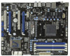
1.3 Motherboard Layout PS2 Keyboard 1 2 34 5 6 24.4cm (9.6-in) USB 2.0 T: USB0 B: USB1 Support 8-Core CPU PWR_FAN1 CPU_FAN2 CPU_FAN1 ATX12V1 LAN PHY Coaxial SPDIF 78 30.5cm (12.0-in) AM3+ HT3.0 Phenom II Optical SPDIF CHA_FAN1 DDR3_B1 (64 bit, 240-FpinSBmo8d0ul0e) DDR3_B2 (64 bit, - ASRock 870 Extreme3 R2.0 | User Manual - Page 13
7 5 8 6 9 17 16 15 14 13 12 11 10 1 USB 2.0 Ports (USB01) * 2 LAN RJ-45 Port 3 USB 2.0 Ports (USB45) 4 Side Speaker (Gray) 5 Rear Speaker (Black) 6 Central / Bass (Orange) 7 Line In (Light Blue) ** 8 Front Speaker (Lime) 9 Microphone (Pink) 10 11 *** 12 13 14 15 16 17 USB 3.0 Port (USB24 - ASRock 870 Extreme3 R2.0 | User Manual - Page 14
Primary output" to use Rear Speaker, Central/Bass, and Front Speaker, or select "Realtek HDA Audio 2nd output" to use front panel audio. *** eSATA3 connector supports SATA Gen3 in cable 1M. 14 - ASRock 870 Extreme3 R2.0 | User Manual - Page 15
2. Installation This is an ATX form factor (12.0-in x 9.6-in, 30.5 cm x 24.4 cm) motherboard. Before you install the motherboard, study the configuration of your chassis to ensure that the motherboard fits into it. Pre-installation Precautions Take note of the following precautions before you - ASRock 870 Extreme3 R2.0 | User Manual - Page 16
. Make sure that the CPU and the heatsink are securely fastened and in good contact with each other. Then connect the CPU fan to the CPU FAN connector (CPU_FAN1, see Page 12, No. 6). For proper installation, please kindly refer to the instruction manuals of the CPU fan and the heatsink. 16 - ASRock 870 Extreme3 R2.0 | User Manual - Page 17
2.3 Installation of Memory Modules (DIMM) This motherboard provides four 240-pin DDR3 (Double Data Rate 3) DIMM slots, and supports Dual Channel Memory Technology. For dual channel configuration, you always need to install identical (the same brand, speed, size and chiptype) DDR3 DIMM pair in - ASRock 870 Extreme3 R2.0 | User Manual - Page 18
adding or removing DIMMs or the system components. Step 1. Step 2. Unlock a DIMM slot by pressing the retaining clips outward. Align a DIMM only fits in one correct orientation. It will cause permanent damage to the motherboard and the DIMM if you force the DIMM into the slot at incorrect - ASRock 870 Extreme3 R2.0 | User Manual - Page 19
cards with x1 lane width cards, such as Gigabit LAN card and SATA2 card. PCIE2 / PCIE4 (PCIE x16 or used to install PCI Express graphics cards to support CrossFireXTM function. 1. In single VGA card mode, Remove the system unit cover (if your motherboard is already installed in a chassis). Step - ASRock 870 Extreme3 R2.0 | User Manual - Page 20
Guide This motherboard supports supported with Windows® XP with Service Pack 2 / VistaTM / 7 OS. Quad CrossFireXTM feature are supported with Windows® VistaTM / 7 OS only. Please check AMD website for ATITM CrossFireXTM driver updates graphics card manuals for detailed installation guide. Step 1. - ASRock 870 Extreme3 R2.0 | User Manual - Page 21
Bridge Interconnects on the top of Radeon graphics cards. (CrossFire Bridge is provided with the graphics card you purchase, not bundled with this motherboard. Please refer to your graphics card vendor for details.) CrossFire Bridge or Step 3. Connect the DVI monitor cable to the DVI connector - ASRock 870 Extreme3 R2.0 | User Manual - Page 22
for ATITM driver updates. Step 3. Step 4. Step 5. Install the required drivers to your system. For Windows® XP OS: A. ATITM recommends Windows® XP Service Pack 2 or higher to be installed (If you have Windows® XP Service Pack 2 or higher installed in your system, there is no need to download it - ASRock 870 Extreme3 R2.0 | User Manual - Page 23
is used only for identification or explanation and to the owners' benefit, without intent to infringe. * For further information of ATITM CrossFireXTM technology, please check AMD website for updates and details. 23 - ASRock 870 Extreme3 R2.0 | User Manual - Page 24
Display Feature This motherboard supports Surround Display upgrade. With the external add-on PCI Express VGA cards, you can easily enjoy the benefits of Surround Display feature. For the detailed instruction, please refer to the document at the following path in the Support CD: ..\ Surround Display - ASRock 870 Extreme3 R2.0 | User Manual - Page 25
P-7 P+7 GND DUMMY 1 GND P+6 P-6 USB_PWR USB_PWR P-9 P+9 GND DUMMY 1 GND P+8 P-8 USB_PWR USB_PWR P-11 P+11 GND DUMMY 1 GND P+10 P-10 USB_PWR Besides six default USB 2.0 ports on the I/O panel, there are three USB 2.0 headers on this motherboard. Each USB 2.0 header can support two USB 2.0 ports. 25 - ASRock 870 Extreme3 R2.0 | User Manual - Page 26
supports Jack Sensing, but the panel wire on the chassis must support HDA to function correctly. Please follow the instruction in our manual and chassis manual activate the front mic. For Windows® XP / XP 64-bit OS: Select "Mixer". Select "Recorder". Then click "FrontMic". For Windows® 7 / 7 64-bit - ASRock 870 Extreme3 R2.0 | User Manual - Page 27
) support, the 3-Pin CPU fan still can work successfully even without the fan speed control function. If you plan to connect the 3-Pin CPU fan to the CPU fan connector on this motherboard, please connect it to Pin 1-3. Pin 1-3 Connected 3-Pin Fan Installation (3-pin CPU_FAN2) (see p.12 No. 5) ATX - ASRock 870 Extreme3 R2.0 | User Manual - Page 28
p.12 No.30) 4-Pin ATX 12V Power Supply Installation 4 1 RXTPAM_0 GND RXTPBM_0 +12V GND 1 +12V RXTPBP_0 GND RXTPAP_0 Besides one default IEEE 1394 port on the I/O panel, there is one IEEE 1394 header (FRONT_1394) on this motherboard. This IEEE 1394 header can support one IEEE 1394 port. RRXD1 - ASRock 870 Extreme3 R2.0 | User Manual - Page 29
2.9 Smart Switches This motherboard has three smart switches: power switch, reset switch and clear CMOS switch, allowing users to quickly turn on/off or reset the system or clear - ASRock 870 Extreme3 R2.0 | User Manual - Page 30
2.10 Dr. Debug Dr. Debug is used to provide code information, which makes troubleshooting even easier. Core is started Pre-memory CPU initialization is started Pre-memory CPU initialization (CPU module specific) Pre-memory CPU initialization (CPU module specific) Pre-memory CPU initialization (CPU - ASRock 870 Extreme3 R2.0 | User Manual - Page 31
not installed Invalid CPU type or Speed CPU mismatch CPU self test failed or possible CPU cache error CPU micro-code is not found or micro-code update is failed Internal CPU error reset PPI Invalid recovery capsule Reserved for future AMI error codes DXE Core is started NVRAM initialization 31 - ASRock 870 Extreme3 R2.0 | User Manual - Page 32
Services CPU DXE initialization is started CPU DXE initialization (CPU module specific) CPU DXE initialization (CPU module specific) CPU DXE initialization (CPU module specific) CPU DXE initialization (CPU Device Selection (BDS) phase is started Driver connecting is started PCI Bus initialization is - ASRock 870 Extreme3 R2.0 | User Manual - Page 33
section below) Ready To Boot event Legacy Boot event Exit Boot Services event Runtime Set Virtual Address MAP Begin Runtime Set Virtual Address future AMI codes OEM BDS initialization codes CPU initialization error North Bridge initialization error update is failed Reset protocol is not available 33 - ASRock 870 Extreme3 R2.0 | User Manual - Page 34
Serial ATA3 (SATA3) Hard Disks Installation This motherboard adopts AMD SB850 chipset that supports Serial ATA3 (SATA3) hard disks and RAID functions. You may install SATA3 hard disks on this motherboard for internal storage devices. This section will guide you to install the SATA3 hard disks. STEP - ASRock 870 Extreme3 R2.0 | User Manual - Page 35
is installed into system properly. The latest SATA3 driver is available on our support website: www.asrock.com 4. Make sure to use the SATA power cable & data cable, which are from our motherboard package. 5. Please follow below instructions step by step to reduce the risk of HDD crash or data - ASRock 870 Extreme3 R2.0 | User Manual - Page 36
cable to (White) to the power supply 1x4-pin cable. the motherboard's SATA3 connector. SATA power cable 1x4-pin power connector (White) Step attention, before you process the Hot Unplug: Please do follow below instruction sequence to process the Hot Unplug, improper procedure will cause the SATA3 - ASRock 870 Extreme3 R2.0 | User Manual - Page 37
to the OS you install. 2.15.1 Installing Windows® XP / XP 64-bit With RAID Functions If you want to install Windows® XP / XP 64-bit on a RAID RAID]. STEP 2: Make a SATA3 Driver Diskette. (Please use USB floppy or floppy disk.) A. Insert the ASRock Support CD into your optical drive to boot - ASRock 870 Extreme3 R2.0 | User Manual - Page 38
refer to the BIOS RAID installation guide part of the document in the following path in the Support CD: .. \ RAID Installation Guide STEP 3: Make a SATA3 Driver Diskette. Make a SATA3 driver diskette by following section 2.15.1 step 2 on page 37. STEP 4: Install Windows® 7 / 7 64-bit / VistaTM - ASRock 870 Extreme3 R2.0 | User Manual - Page 39
OS on your system. At the beginning of Windows® setup, press F6 to install a third-party AHCI driver. When prompted, insert the SATA3 driver diskette containing the AMD AHCI driver. After reading the floppy disk, the driver will be presented. Select the driver to install according to the OS you - ASRock 870 Extreme3 R2.0 | User Manual - Page 40
Set the "SATA Mode" option to [IDE]. STEP 2: Install Windows® 7 / 7 64-bit / VistaTM / VistaTM 64-bit OS on your system. 2.17 Untied Overclocking Technology This motherboard supports Untied Overclocking Technology, which means during overclocking, FSB enjoys better margin due to fixed PCI / PCIE - ASRock 870 Extreme3 R2.0 | User Manual - Page 41
. The SPI Memory on the motherboard stores the UEFI SETUP UTILITY. You Self-Test (POST) to enter the UEFI SETUP UTILITY, otherwise, POST will continue with its test software is constantly being updated, the following UEFI setup screens OC Tweaker To set up overclocking features Advanced To set up - ASRock 870 Extreme3 R2.0 | User Manual - Page 42
3.1.2 Navigation Keys Please check the following table for the function description of each navigation key. Navigation Key(s) / / + / Function Description Moves cursor left or right to select Screens Moves cursor up or down to select items To change option for the - ASRock 870 Extreme3 R2.0 | User Manual - Page 43
Mode Use this to select Overclock Mode. Configuration options: [Auto] and [Manual]. The default value is [Auto]. Spread Spectrum This item should always be [Auto] for better system stability. ASRock UCC ASRock UCC (Unlock CPU Core) feature simplifies AMD CPU activation. As long as a simple switch - ASRock 870 Extreme3 R2.0 | User Manual - Page 44
Manual], you may adjust the value of Processor Frequency and Processor Voltage. However, it is recommended to keep the default value for system stability. CPU Frequency (MHz) Use this option to adjust CPU frequency. CPU If [Auto] is selected, the motherboard will detect the memory module(s) inserted - ASRock 870 Extreme3 R2.0 | User Manual - Page 45
], [Address bits 6], [Address bits 12], [HASH 1] and [HASH 2]. The default value is [HASH 2]. CAS# Latency (tCL) Use this item to change CAS# Latency (tCL) Auto/Manual setting. The default is [Auto]. RAS# to CAS# Delay (tRCD) Use this item to change RAS# to CAS# Delay (tRCD) Auto - ASRock 870 Extreme3 R2.0 | User Manual - Page 46
change Four Activate Window (tFAW) Auto/Manual setting. The default is [Auto]. Voltage Control DRAM Voltage Use this to select DRAM Voltage. The default value is [Auto]. NB Voltage Use this to select NB Voltage. The default value is [Auto]. CPU Load-Line Calibration CPU Load-Line Calibration helps - ASRock 870 Extreme3 R2.0 | User Manual - Page 47
section may cause the system to malfunction. ASRock Instant Flash ASRock Instant Flash is a UEFI flash utility embedded in Flash ROM. This convenient UEFI update tool allows you to update system UEFI without entering operating systems first like MS-DOS or Windows®. Just launch this tool and save the - ASRock 870 Extreme3 R2.0 | User Manual - Page 48
). The C1 state is supported through the native processor instructions HLT and MWAIT and requires no hardware support from the chipset. In the C1 power state, the processor maintains the context of the system caches. CPU Thermal Throttle Use this item to enable CPU internal thermal control mechanism - ASRock 870 Extreme3 R2.0 | User Manual - Page 49
PCI Sound Card is plugged. Front Panel Select [Auto] or [Disabled] for the onboard HD Audio Front Panel. Onboard LAN This allows you to enable or disable the onboard LAN feature. Onboard 1394 controller This allows you to enable or disable the onboard 1394 controller. Onboard Debug Port LED This - ASRock 870 Extreme3 R2.0 | User Manual - Page 50
Mode]. Configuration options: [AHCI Mode], [RAID Mode] and [IDE Mode]. If you set this item to RAID mode, it is suggested to install SATA ODD driver on SATA3_5 port. SATA IDE Combined Mode This item is for SATA3_5 and eSATA ports only. Use this item to enable or disable SATA IDE - ASRock 870 Extreme3 R2.0 | User Manual - Page 51
3.4.4 Super IO Configuration Serial Port Use this item to enable or disable the onboard serial port. Serial Port Address Use this item to set the address for the onboard serial port. Configuration options: [Auto], [3F8 / IRQ4] and [3E8 / IRQ4]. Infrared Port Use this item to enable or disable the - ASRock 870 Extreme3 R2.0 | User Manual - Page 52
-detect or disable the Suspend-toRAM feature. Select [Auto] will enable this feature if the OS supports it. Check Ready Bit Use this item to enable or disable the feature Check Ready Bit. Restore this option to [Enabled] if you plan to use this motherboard to submit Windows® VistaTM certification. 52 - ASRock 870 Extreme3 R2.0 | User Manual - Page 53
compatibility issue, it is recommended to select [Disabled] to enter OS. [UEFI Setup Only] - USB devices are allowed to use only under UEFI setup and Windows / Linux OS. Legacy USB 3.0 Support Use this option to enable or disable legacy support for USB 3.0 devices. The default value is [Enabled]. 53 - ASRock 870 Extreme3 R2.0 | User Manual - Page 54
CPU temperature, motherboard temperature, CPU fan speed, chassis fan speed, and the critical voltage. CPU Fan 1 & 2 Setting This allows you to set the CPU the chassis fan 2 speed. Confi guration options: [Full On] and [Manual Mode]. The default is value [Full On]. Chassis Fan 3 Setting This allows - ASRock 870 Extreme3 R2.0 | User Manual - Page 55
, please select [Enabled]. Configuration options: [Enabled] and [Disabled]. The default value is [Enabled]. Boot From Onboard LAN Use this item to enable or disable the Boot From Onboard LAN feature. Boot Failure Guard Enable or disable the feature of Boot Failure Guard. Boot Failure Guard Count - ASRock 870 Extreme3 R2.0 | User Manual - Page 56
3.7 Security Screen In this section, you may set or change the supervisor/user password for the system. For the user password, you may also clear it. 56 - ASRock 870 Extreme3 R2.0 | User Manual - Page 57
3.8 Exit Screen Save Changes and Exit When you select this option, it will pop-out the following message, "Save configuration changes and exit setup?" Select [OK] to save the changes and exit the UEFI SETUP UTILITY. Discard Changes and Exit When you select this option, it will pop-out the following - ASRock 870 Extreme3 R2.0 | User Manual - Page 58
install the necessary drivers to activate the devices. 4.2.3 Utilities Menu The Utilities Menu shows the applications software that the motherboard supports. Click on a specific item then follow the installation wizard to install it. 4.2.4 Contact Information If you need to contact ASRock or want to - ASRock 870 Extreme3 R2.0 | User Manual - Page 59
HDD Larger Than 2TB This motherboard is adopting UEFI BIOS that allows Windows® OS to be installed on a large size HDD (>2TB). Please follow below procedure to install the operating system. 1. Please make sure to use Windows® VistaTM 64-bit (with SP1 or above) or Windows® 7 64-bit. 2. Set AHCI Mode
-
 1
1 -
 2
2 -
 3
3 -
 4
4 -
 5
5 -
 6
6 -
 7
7 -
8
-
9
-
10
-
11
-
12
-
13
-
14
-
15
-
16
-
17
-
18
-
19
-
20
-
21
-
22
-
23
-
24
-
25
-
26
-
27
-
28
-
29
-
30
-
31
-
32
-
33
-
34
-
35
-
36
-
37
-
38
-
39
-
40
-
41
-
42
-
43
-
44
-
45
-
46
-
47
-
48
-
49
-
50
-
51
-
52
-
53
-
54
-
55
-
56
-
57
-
58
-
59
 |
 |

1
870 Extreme3
User Manual
Version 2.0
Published March 2011
Copyright©2011 ASRock INC. All rights reserved.