ASRock 880GM-LE User Manual
ASRock 880GM-LE Manual
 |
View all ASRock 880GM-LE manuals
Add to My Manuals
Save this manual to your list of manuals |
ASRock 880GM-LE manual content summary:
- ASRock 880GM-LE | User Manual - Page 1
880GM-LE User Manual Version 1.0 Published April 2010 Copyright©2010 ASRock INC. All rights reserved. 1 - ASRock 880GM-LE | User Manual - Page 2
without written consent of ASRock Inc. Products and corporate names appearing in this manual may or may not be intent to infringe. Disclaimer: Specifications and information contained in this manual are furnished for informational use battery adopted on this motherboard contains Perchlorate, a toxic - ASRock 880GM-LE | User Manual - Page 3
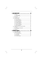
Installation of CPU Fan and Heatsink 14 2.3 Installation of Memory Modules (DIMM 15 2.4 Expansion Slots (PCI and PCI Express Slots 16 2.5 Dual Monitor and Surround Display Features 17 2.6 ATITM Hybrid CrossFireXTM Operation Guide 20 2.7 Jumpers Setup 22 2.8 Onboard Headers and Connectors 23 - ASRock 880GM-LE | User Manual - Page 4
Screen 56 3.6 Boot Screen 57 3.6.1 Boot Settings Configuration 57 3.7 Security Screen 58 3.8 Exit Screen 59 4 . Software Support 60 4.1 Install Operating System 60 4.2 Support CD Information 60 4.2.1 Running Support CD 60 4.2.2 Drivers Menu 60 4.2.3 Utilities Menu 60 4.2.4 Contact - ASRock 880GM-LE | User Manual - Page 5
our website for specific information about the model you are using. www.asrock.com/support/index.asp 1.1 Package Contents 1 x ASRock 880GM-LE Motherboard (Micro ATX Form Factor: 9.6-in x 7.8-in, 24.4 cm x 19.8 cm) 1 x ASRock 880GM-LE Quick Installation Guide 1 x ASRock 880GM-LE Support CD 1 x Ultra - ASRock 880GM-LE | User Manual - Page 6
1.2 Specifications Platform CPU Chipset Memory Expansion Slot Graphics Audio LAN - Micro ATX Form Factor: 9.6-in x 7.8-in, 24.4 cm x 19.8 cm - Support for Socket AM3 processors: AMD PhenomTM II X4 / X3 / X2 (except 920 / 940) / Athlon II X4 / X3 / X2 / Sempron processors - Six-Core CPU Ready - - ASRock 880GM-LE | User Manual - Page 7
port header - 1 x COM port header - CPU/Chassis/Power FAN connector - 24 pin ATX power connector - 4 pin 12V power connector - CD in header - Front panel audio connector - 3 x USB 2.0 headers (support 6 USB 2.0 ports) (see CAUTION 7) - 8Mb AMI BIOS - AMI Legal BIOS - Supports "Plug and Play" - ACPI - ASRock 880GM-LE | User Manual - Page 8
. 3. Whether 1800/1600MHz memory speed is supported depends on the AM3 CPU you adopt. If you want to adopt DDR3 1800/1600 memory module on this motherboard, please refer to the memory support list on our website for the compatible memory modules. ASRock website http://www.asrock.com 4. Due to the - ASRock 880GM-LE | User Manual - Page 9
embedded in Flash ROM. This convenient BIOS update tool allows you to update system BIOS without entering operating systems first like MS-DOS or Windows®. With this utility, you can press key during the POST or press key to BIOS setup menu to access ASRock Instant Flash. Just launch this - ASRock 880GM-LE | User Manual - Page 10
under 1.00W in off mode condition. To meet EuP standard, an EuP ready motherboard and an EuP ready power supply are required. According to Intel's suggestion, the EuP ready power supply must meet the standard of 5v standby power efficiency is higher than 50% under 100 mA current consumption. For EuP - ASRock 880GM-LE | User Manual - Page 11
BATTERY USB 2.0 T: USB2 B: USB3 USB 2.0 T: USB4 B: USB5 CLRCMOS1 1 1 COM1 FSB2.6GHz Phenom USB 2.0 T: USB0 B: USB1 Top: RJ-45 Top: LINE IN Center: FRONT Bottom: MIC IN LAN AUDIO CODEC Super I/O CD1 1 HD_AUDIO1 LPT1 1 PCIE1 AMD 880G Chipset Hybrid CrossFire PCIE2 880GM-LE IDE1 PWR_FAN1 - ASRock 880GM-LE | User Manual - Page 12
connection LAN Port To enable Multi-Streaming function, you need to connect a front panel audio cable to the front panel audio header. Please refer to below steps for the software setting of Multi-Streaming. For Windows® XP: After restarting your computer, you will find "Mixer" tool on your - ASRock 880GM-LE | User Manual - Page 13
2. Installation This is a Micro ATX form factor (9.6-in x 7.8-in, 24.4 cm x 19.8 cm) motherboard. Before you install the motherboard, study the configuration of your chassis to ensure that the motherboard fits into it. Pre-installation Precautions Take note of the following precautions before you - ASRock 880GM-LE | User Manual - Page 14
. Make sure that the CPU and the heatsink are securely fastened and in good contact with each other. Then connect the CPU fan to the CPU FAN connector (CPU_FAN1, see Page 11, No. 6). For proper installation, please kindly refer to the instruction manuals of the CPU fan and the heatsink. 14 - ASRock 880GM-LE | User Manual - Page 15
of Memory Modules (DIMM) 880GM-LE motherboard provides two 240-pin DDR3 (Double Data Rate 3) DIMM slots, and supports Dual Channel Memory Technology. For dual channel configuration, you always need to install two identical (the same brand, speed, size and chiptype) memory modules in the DDR3 DIMM - ASRock 880GM-LE | User Manual - Page 16
power cord is unplugged. Please read the documentation of the expansion card and make necessary hardware settings for the card before you start the installation. Step 2. Remove the bracket facing the slot that you intend to use. Keep the screws for later use. Step 3. Align the card connector with - ASRock 880GM-LE | User Manual - Page 17
This motherboard supports surround display upgrade. With the internal dual VGA output support (DVI-D and D-Sub) and the external add-on PCI Express VGA card, you can easily enjoy the benefits of surround display feature. Please refer to the following steps to set up a surround display environment - ASRock 880GM-LE | User Manual - Page 18
is less than the total capability of the system memory. If you do not adjust the BIOS setup, the default value of "Share Memory", [Auto], will disable VGA/D-Sub function when the add-on VGA card is inserted to this motherboard. 4. Install the onboard VGA driver and the add-on PCI Express VGA card - ASRock 880GM-LE | User Manual - Page 19
function is supported on this motherboard. To use HDCP function with this motherboard, you need to adopt the monitor that supports HDCP function as well. Therefore, you can enjoy the superior display quality with high-definition HDCP encryption contents. Please refer to below instruction for more - ASRock 880GM-LE | User Manual - Page 20
3450 series graphics processor and a motherboard based on an AMD 880G integrated chipset, all operating in a Windows® VistaTM / 7 environment. Please refer to below PCI Express graphics card support list for ATITM Hybrid CrossFireXTM. For the future update of more compatible PCI Express graphics - ASRock 880GM-LE | User Manual - Page 21
used only for identification or explanation and to the owners' benefit, without intent to infringe. * For further information of ATITM Hybrid CrossFireXTM technology, please check AMD website for up dates and details. 21 - ASRock 880GM-LE | User Manual - Page 22
the system parameters to default setup, please turn off the computer and unplug the power cord from the power supply. After waiting for 15 seconds, use a jumper cap to short pin2 and pin3 on CLRCMOS1 for 5 seconds. However, please do not clear the CMOS right after you update the BIOS. If you need to - ASRock 880GM-LE | User Manual - Page 23
plugged into Pin1 side of the connector. Primary IDE connector (Blue) (39-pin IDE1, see p.11 No. 10) PIN1 IDE1 connect the blue end to the motherboard connect the black end to the IDE devices 80-conductor ATA 66/100/133 cable Note: Please refer to the instruction of your IDE device vendor for - ASRock 880GM-LE | User Manual - Page 24
USB_PWR P-9 P+9 GND DUMMY 1 GND P+8 P-8 USB_PWR USB_PWR P-7 P+7 GND DUMMY Besides six default USB 2.0 ports on the I/O panel, there are three USB 2.0 headers on this motherboard. Each USB 2.0 header can support two USB 2.0 ports. 1 GND P+6 P-6 USB_PWR AFD# ERROR# PINIT# SLIN# GND 1 SPD7 SPD6 - ASRock 880GM-LE | User Manual - Page 25
only. You don't need to connect them for AC'97 audio panel. E. Enter BIOS Setup Utility. Enter Advanced Settings, and then select Chipset Configuration. Set the Front Panel Control option from [Auto] to [Enabled]. F. Enter Windows system. Click the icon on the lower right hand taskbar to enter - ASRock 880GM-LE | User Manual - Page 26
CPU fan to the CPU fan connector on this motherboard, please connect it to Pin 1-3. Pin 1-3 Connected 3-Pin Fan Installation ATX Power Connector (24-pin ATXPWR1) (see p.11 No. 8) 12 24 Please connect an ATX power supply to this connector. 1 13 Though this motherboard provides 24-pin ATX power - ASRock 880GM-LE | User Manual - Page 27
CCTS#1 1 RRI#1 RRTS#1 GND TTXD1 DDCD#1 This COM1 header supports a serial port module. 2.9 SATAII Hard Disk Setup Guide Before installing SATAII hard disk to your computer, please carefully read below SATAII hard disk setup guide. Some default setting of SATAII hard disks may not be at SATAII mode - ASRock 880GM-LE | User Manual - Page 28
adopts AMD SB710 south bridge chipset that supports Serial ATA (SATA) / Serial ATAII (SATAII) hard disks and RAID (RAID 0, RAID 1, RAID 10 and JBOD) functions. You may install SATA / SATAII hard disks on this motherboard for internal storage devices. This section will guide you to install - ASRock 880GM-LE | User Manual - Page 29
motherboard supports Hot Plug and Hot Swap functions for SATA / SATAII Devices in RAID / AHCI mode. AMD SB710 south bridge chipset provides hardware support set for RAID configuration, it is called "Hot Plug" for the action to insert and remove the SATA / SATAII HDDs while the system is still power- - ASRock 880GM-LE | User Manual - Page 30
is installed into system properly. The latest SATA / SATAII driver is available on our support website: www.asrock.com 4. Make sure to use the SATA power cable & data cable, which are from our motherboard package. 5. Please follow below instructions step by step to reduce the risk of HDD crash or - ASRock 880GM-LE | User Manual - Page 31
instruction sequence to process the Hot Plug, improper procedure will cause the SATA / SATAII HDD damage and data loss. Step 1 Please connect SATA power cable 1x4-pin end Step 2 Connect SATA data cable to (White) to the power supply 1x4-pin cable. the motherboard's SATAII connector. SATA power - ASRock 880GM-LE | User Manual - Page 32
RAID functions, please follow below steps. STEP 1: Set up BIOS. A. Enter BIOS SETUP UTILITY Advanced screen Storage Configuration. B. Set the "SATA Operation Mode" option to [RAID]. STEP 2: Make a SATA / SATAII Driver Diskette. A. Insert the ASRock Support CD into your optical drive to boot - ASRock 880GM-LE | User Manual - Page 33
path in the Support CD: .. \ RAID Installation Guide STEP 4: Install Windows® XP / XP 64-bit OS on your system. After step 1, 2, 3, you can start to install Windows® XP / XP 64-bit OS on your system. At the beginning of Windows® setup, press F6 to install a third-party RAID driver. When prompted - ASRock 880GM-LE | User Manual - Page 34
up "SATA Operation Mode" to [RAID] in BIOS first. Then, please set the RAID configuration by using the Windows RAID installation guide in the following path in the Support CD: .. \ RAID Installation Guide NOTE2. Currently, if you install Windows® 7 / 7 64-bit / VistaTM / VistaTM 64-bit on IDE HDDs - ASRock 880GM-LE | User Manual - Page 35
SATA / SATAII HDDs with NCQ and Hot Plug functions (AHCI mode) STEP 1: Set Up BIOS. A. Enter BIOS SETUP UTILITY Advanced screen Storage Configuration. B. Set the "SATA Operation Mode" option to [AHCI]. STEP 2: Install Windows® 7 / 7 64-bit / VistaTM / VistaTM 64-bit OS on your system. Using - ASRock 880GM-LE | User Manual - Page 36
This motherboard supports Untied Overclocking Technology, which means during overclocking, FSB enjoys better margin due to fixed PCI / PCIE buses. Before you enable Untied Overclocking function, please enter "Overclock Mode" option of BIOS setup to set the selection from [Auto] to [CPU, PCIE - ASRock 880GM-LE | User Manual - Page 37
This section explains how to use the BIOS SETUP UTILITY to configure your system. The SPI Memory on the motherboard stores the BIOS SETUP UTILITY. You may run the BIOS SETUP UTILITY when you start up the computer. Please press or during the Power-On-Self-Test (POST) to enter the - ASRock 880GM-LE | User Manual - Page 38
[17:00:09] [Mon 04/12/2010] BIOS Version : 880GM-LE P1.0 Processor Type : AMD Phenom(tm) II X3 720 Processor (64bit) Processor Speed : 2800MHz Microcode Update : 100F42/1000086 L1 Cache Size : 384KB L2 Cache Size : 1536KB L3 Cache Size : 6144KB Total Memory DDR3_A1 DDR3_B1 : 2048MB Single-Channel - ASRock 880GM-LE | User Manual - Page 39
OC Tweaker screen, you can set up overclocking features. BIOS SETUP UTILITY Main OC Tweaker Advanced H/W Monitor Boot Security Exit EZ Overclocking Load Optimized CPU OC Setting [Press Enter] Load Optimized mGPU OC Setting [Press Enter] CPU Configuration Overclock Mode CPU Frequency (MHz) PCIE - ASRock 880GM-LE | User Manual - Page 40
it is set to [Manual], you may adjust the value of Processor Frequency and Processor Voltage. However, it is recommended to keep the default value for system stability. BIOS SETUP UTILITY Main OC Tweaker Advanced H/W Monitor Boot Security Exit EZ Overclocking Load Optimized CPU OC Setting [Press - ASRock 880GM-LE | User Manual - Page 41
Bit]. Memory Configuration Memory Clock This item can be set by the code using [Auto]. You can set one of the standard values as listed: [ value is [Auto]. DRAM Timing BIOS SETUP UTILITY OC Tweaker DRAM Timing Memory Controller Mode Power Down Enable Bank Interleaving Channel Interleaving CAS - ASRock 880GM-LE | User Manual - Page 42
This option appears only when you adopt Phenom CPU. It allows you to enable Channel Memory Interleaving. Configuration options: [Disabled], [XOR 20:16, 9]]. CAS Latency (CL) Use this item to adjust the means of memory accessing. Configuration options: [Auto], [4CLK] to [12CLK]. The default value is - ASRock 880GM-LE | User Manual - Page 43
ODT Delay feature. Configuration options: [Auto], [No Delay], [1/64CLK] to [31/64CLK]. The default value is [Auto]. CHA CS/ODT Setup Use this to adjust values for CHA CS/ODT Setup feature. Configuration options: [Auto], [1/2CLK] and [1CLK]. The default value is [Auto]. CHB ADDR/CMD Delay Use this to - ASRock 880GM-LE | User Manual - Page 44
CHA CKE Drive Use this to adjust values for CHA CKE Drive. Configuration options: [Auto], [1.00x], [1.25x], [1.50x] and [2.00x]. The default value is [Auto]. CHA CS/ODT Drive Use this to adjust values for CHA CS/ODT Drive. Configuration options: [Auto], [1.00x], [1.25x], [1.50x] and [2.00x]. The - ASRock 880GM-LE | User Manual - Page 45
Chipset Settings Onboard GPU Clock Override This allows you to enable or disable the [Auto], [1.10V] to [1.45V]. The default value is [Auto]. Would you like to save current setting user defaults? In this option, you are allowed to load and save three user defaults according to your own requirements. - ASRock 880GM-LE | User Manual - Page 46
Inc. Setting wrong values in this section may cause the system to malfunction. ASRock Instant Flash ASRock Instant Flash is a BIOS flash utility embedded in Flash ROM. This convenient BIOS update tool allows you to update system BIOS without entering operating systems first like MS-DOS or Windows - ASRock 880GM-LE | User Manual - Page 47
L3 Cache Allocation CPU Thermal Throttle BIOS SETUP UTILITY [Auto] [Enabled] [Disabled] [Auto] [Auto] Enabling this function may reduce CPU voltage and memory freq., and lead to system stability or compatibility issue with some memory modules or power supplies. Please set this item to [Disabled - ASRock 880GM-LE | User Manual - Page 48
3.4.2 Chipset Configuration BIOS SETUP UTILITY Advanced Chipset Settings Onboard HD Audio Front Panel OnBoard Lan Dr. LAN Link speed : 10Mbps Primary Graphics Adapter Share Memory Onboard HDMI HD Audio Surround View [Auto] [Auto] [Enabled] [PCI] [Auto] [Disabled] [Disabled] +F1 F9 F10 ESC - ASRock 880GM-LE | User Manual - Page 49
3.4.3 ACPI Configuration BIOS SETUP UTILITY Advanced ACPI Settings Suspend To RAM Away Mode Support Restore on AC / Power Loss Ring-In Power On PCI Devices Power On PS / 2 Keyboard Power On RTC Alarm Power On ACPI HPET Table [Disabled] [Disabled] [Power Off] [Disabled] [Disabled] [Disabled] [ - ASRock 880GM-LE | User Manual - Page 50
or disable ACPI HPET Table. The default value is [Disabled]. Please set this option to [Enabled] if you plan to use this motherboard to submit Windows® VistaTM certification. 3.4.4 Storage Configuration BIOS SETUP UTILITY Advanced Storage Configuration Onboard SATA Controller SATA Operation Mode - ASRock 880GM-LE | User Manual - Page 51
disk drive. After selecting the hard disk information into BIOS, use a disk utility, such as FDISK, to partition mode for a hard disk > 512 MB under DOS and Windows; for Netware and UNIX user, select [Disabled] to transfer. PIO Mode Use this item to set the PIO mode to enhance hard disk performance - ASRock 880GM-LE | User Manual - Page 52
3.4.5 PCIPnP Configuration BIOS SETUP UTILITY Advanced Advanced PCI / PnP Settings PCI Latency Timer PCI IDE BusMaster [32] [ keep the default value unless the installed PCI expansion cards' specifications require other settings. PCI IDE BusMaster Use this item to enable or disable the PCI IDE - ASRock 880GM-LE | User Manual - Page 53
American Megatrends, Inc. 3.4.7 Super IO Configuration BIOS SETUP UTILITY Advanced Configure Super IO Chipset OnBoard Floppy enable or disable floppy drive controller. Serial Port Address Use this item to set the address for the onboard serial port or disable it. Configuration options: [Disabled - ASRock 880GM-LE | User Manual - Page 54
or disable it. Configuration options: [Disabled], [378], and [278]. Parallel Port Mode Use this item to set the operation mode of the parallel port. The default value is [ECP+EPP]. If this option is set to [ECP+EPP], it will show the EPP version in the following item, "EPP Version". Configuration - ASRock 880GM-LE | User Manual - Page 55
is recommended to select [Disabled] to enter OS. [BIOS Setup Only] - USB devices are allowed to use only under BIOS setup and Windows / Linux OS. USB Keyboard/Remote Power On Use this item to enable or disable USB Keyboard/Remote Power On on the system. USB Mouse Power On Use this item to enable or - ASRock 880GM-LE | User Manual - Page 56
, motherboard temperature, CPU fan speed, chassis fan speed, and the critical voltage. BIOS SETUP UTILITY Main OC Tweaker Advanced H/W Monitor Boot Security Exit Hardware Health Event Monitoring CPU Temperature M / B Temperature CPU Fan Speed Chassis Fan Speed Power Fan Speed Vcore + 3.30V - ASRock 880GM-LE | User Manual - Page 57
C] [USB] Select Screen Select Item Enter Go to Sub Screen F1 General Help F9 Load Defaults F10 Save and Exit ESC Exit v02.54 (C) Copyright 1985-2005, American Megatrends, Inc. 3.6.1 Boot Settings Configuration BIOS SETUP UTILITY Boot Boot Settings Configuration Full Screen Logo AddOn ROM Display - ASRock 880GM-LE | User Manual - Page 58
options: [Auto], [EuP], [Scenery] and [ASRock]. The default value is [Auto]. Currently, the option [Auto] is set to Aircraft. Boot From Onboard LAN Use this may also clear it. BIOS SETUP UTILITY Main OC Tweaker Advanced H/W Monitor Boot Security Exit Security Settings Supervisor Password : Not - ASRock 880GM-LE | User Manual - Page 59
BIOS Defaults Load Performance Setup Default (IDE/SATA) Load Performance Setup AHCI Mode Load Performance Setup RAID Mode Load Power Saving Setup Default Exit system setup optimal default settings. F5 key can be used for this operation. Load Performance Setup AHCI Mode This performance setup AHCI - ASRock 880GM-LE | User Manual - Page 60
install the necessary drivers to activate the devices. 4.2.3 Utilities Menu The Utilities Menu shows the applications software that the motherboard supports. Click on a specific item then follow the installation wizard to install it. 4.2.4 Contact Information If you need to contact ASRock or want to
-
 1
1 -
 2
2 -
 3
3 -
 4
4 -
 5
5 -
 6
6 -
 7
7 -
8
-
9
-
10
-
11
-
12
-
13
-
14
-
15
-
16
-
17
-
18
-
19
-
20
-
21
-
22
-
23
-
24
-
25
-
26
-
27
-
28
-
29
-
30
-
31
-
32
-
33
-
34
-
35
-
36
-
37
-
38
-
39
-
40
-
41
-
42
-
43
-
44
-
45
-
46
-
47
-
48
-
49
-
50
-
51
-
52
-
53
-
54
-
55
-
56
-
57
-
58
-
59
-
60
 |
 |

1
880GM-LE
User Manual
Version 1.0
Published April 2010
Copyright©2010 ASRock INC. All rights reserved.