ASRock 890GM Pro3 R2.0 User Manual
ASRock 890GM Pro3 R2.0 Manual
 |
View all ASRock 890GM Pro3 R2.0 manuals
Add to My Manuals
Save this manual to your list of manuals |
ASRock 890GM Pro3 R2.0 manual content summary:
- ASRock 890GM Pro3 R2.0 | User Manual - Page 1
890GM Pro3 User Manual Version 2.0 Published January 2011 Copyright©2011 ASRock INC. All rights reserved. 1 - ASRock 890GM Pro3 R2.0 | User Manual - Page 2
purchaser for backup purpose, without written consent of ASRock Inc. Products and corporate names appearing in this manual may or may not be registered trademarks or copyrights USA ONLY The Lithium battery adopted on this motherboard contains Perchlorate, a toxic substance controlled in Perchlorate - ASRock 890GM Pro3 R2.0 | User Manual - Page 3
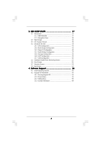
1.1 Package Contents 5 1.2 Specifications 6 1.3 Motherboard Layout 12 1.4 I/O Panel 13 2 . SATA3 HDDs 30 2.11 SATA3 HDD Hot Plug Feature and Operation Guide 31 2.12 Driver Installation Guide 33 2.13 Installing Windows® 7 / 7 64-bit / Functions 36 2.15 Untied Overclocking Technology 36 3 - ASRock 890GM Pro3 R2.0 | User Manual - Page 4
Health Event Monitoring Screen 51 3.6 Boot Screen 52 3.7 Security Screen 53 3.8 Exit Screen 54 4 . Software Support 55 4.1 Install Operating System 55 4.2 Support CD Information 55 4.2.1 Running Support CD 55 4.2.2 Drivers Menu 55 4.2.3 Utilities Menu 55 4.2.4 Contact Information 55 4 - ASRock 890GM Pro3 R2.0 | User Manual - Page 5
about the model you are using. www.asrock.com/support/index.asp 1.1 Package Contents ASRock 890GM Pro3 Motherboard (Micro ATX Form Factor: 9.6-in x 9.6-in, 24.4 cm x 24.4 cm) ASRock 890GM Pro3 Quick Installation Guide ASRock 890GM Pro3 Support CD 2 x Serial ATA (SATA) Data Cables (Optional - ASRock 890GM Pro3 R2.0 | User Manual - Page 6
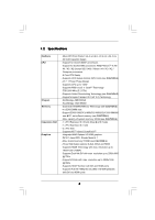
1.2 Specifications Platform CPU Chipset Memory Expansion Slot Graphics - Micro ATX Form Factor: 9.6-in x 9.6-in, 24.4 cm x 24.4 cm - All Solid Capacitor design - Support for Socket AM3+ processors - Support for Socket AM3 processors: AMD PhenomTM II X6 / X4 / X3 / X2 (except 920 / 940) / Athlon II - ASRock 890GM Pro3 R2.0 | User Manual - Page 7
- 1 x IEEE 1394 header - CPU/Chassis/Power FAN connector - 24 pin ATX power connector - 8 pin 12V power connector - Front panel audio connector - 3 x USB 2.0 headers (support 6 USB 2.0 ports) - 32Mb AMI UEFI Legal BIOS with GUI support - Supports "Plug and Play" - ACPI 1.1 Compliance Wake Up Events - ASRock 890GM Pro3 R2.0 | User Manual - Page 8
visit our website: http://www.asrock.com WARNING Please realize that there is a certain risk involved with overclocking, including adjusting the setting in the BIOS, applying Untied Overclocking Technology, or using the thirdparty overclocking tools. Overclocking may affect your system stability - ASRock 890GM Pro3 R2.0 | User Manual - Page 9
switch of the UEFI option "ASRock UCC", you can unlock price. Please be noted that UCC feature is supported with AM3/AM3+ CPU only, and in addition, not every AM3/AM3+ CPU can support this function because some CPU's hidden core may be malfunctioned. 2. This motherboard supports Untied Overclocking - ASRock 890GM Pro3 R2.0 | User Manual - Page 10
40% faster than before. ASRock APP Charger allows you to quickly charge many Apple devices simultaneously and even supports continuous charging when your PC enters into Standby mode (S1), Suspend to RAM (S3), hibernation mode (S4) or power off (S5). With APP Charger driver installed, you can easily - ASRock 890GM Pro3 R2.0 | User Manual - Page 11
you resume the system, please check if the CPU fan on the motherboard functions properly and unplug the power cord, then plug it back again. 1.00W in off mode condition. To meet EuP standard, an EuP ready motherboard and an EuP ready power supply are required. According to Intel's suggestion, the - ASRock 890GM Pro3 R2.0 | User Manual - Page 12
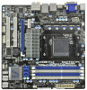
Support 8-Core CPU FSB2.6GHz 1.3 Motherboard Layout 1 USB 2.0 T: USB2 B: USB3 2 24.4cm (9.6-in) 34 CPU_FAN1 HT3.0 DX10.1 AM3+ 56 PS2 Keyboard DVI_CON1 VGA1 ATX12V1 7 140W CPU 890GM Pro3 Phenom II SOCKET AMD 32Mb BIOS SB850 Port Connector (COM1) 7 ATX Power Connector (ATXPWR1) 24 - ASRock 890GM Pro3 R2.0 | User Manual - Page 13
1.4 I/O Panel 1 2 16 15 1 USB 2.0 Ports (USB23) 2 VGA/D-Sub Port 3 USB 2.0 Ports (USB45) * 4 LAN RJ-45 Port 5 Central / Bass (Orange) 6 Rear Speaker (Black) 7 Optical SPDIF Out Port 8 Line In (Light Blue) 34 58 69 7 10 14 13 12 11 ** 9 10 11 *** 12 13 14 15 16 Front Speaker (Lime) - ASRock 890GM Pro3 R2.0 | User Manual - Page 14
Primary output" to use Rear Speaker, Central/Bass, and Front Speaker, or select "Realtek HDA Audio 2nd output" to use front panel audio. *** eSATA3 connector supports SATA Gen3 in cable 1M. 14 - ASRock 890GM Pro3 R2.0 | User Manual - Page 15
2. Installation This is a Micro ATX Form Factor (9.6-in x 9.6-in, 24.4 cm x 24.4 cm) motherboard. Before you install the motherboard, study the configuration of your chassis to ensure that the motherboard fits into it. Pre-installation Precautions Take note of the following precautions before you - ASRock 890GM Pro3 R2.0 | User Manual - Page 16
Triangle To The Socket Corner Small Triangle STEP 4: Push Down And Lock The Socket Lever 2.2 Installation of CPU Fan and Heatsink After you install the CPU into this motherboard, it is For proper installation, please kindly refer to the instruction manuals of the CPU fan and the heatsink. 16 - ASRock 890GM Pro3 R2.0 | User Manual - Page 17
2.3 Installation of Memory Modules (DIMM) This motherboard provides four 240-pin DDR3 (Double Data Rate 3) DIMM slots, and supports Dual Channel Memory Technology. For dual channel configuration, you always need to install identical (the same brand, speed, size and chiptype) DDR3 DIMM pair in - ASRock 890GM Pro3 R2.0 | User Manual - Page 18
matches the break on the slot. notch break notch break The DIMM only fits in one correct orientation. It will cause permanent damage to the motherboard and the DIMM if you force the DIMM into the slot at incorrect orientation. Step 3. Firmly insert the DIMM into the slot until the retaining - ASRock 890GM Pro3 R2.0 | User Manual - Page 19
the expansion card and make necessary hardware settings for the card before you start the installation. Step 2. Remove the system unit cover (if your motherboard is already installed in a chassis). Step 3. Remove the bracket facing the slot that you intend to use. Keep the screws for later use. Step - ASRock 890GM Pro3 R2.0 | User Manual - Page 20
after your system boots. If you haven't installed onboard VGA driver yet, please install onboard VGA driver from our support CD to your system and restart your computer. Then you can start to use dual monitor function on this motherboard. 1. DVI-D and HDMI ports cannot function at the same time - ASRock 890GM Pro3 R2.0 | User Manual - Page 21
Display Feature This motherboard supports surround display upgrade. With the internal VGA output support (DVI-D, D-Sub is inserted to this motherboard. 4. Install the onboard VGA driver and the add-on PCI Express VGA card driver to your system. If you have installed the drivers already, there is - ASRock 890GM Pro3 R2.0 | User Manual - Page 22
function is supported on this motherboard. To use HDCP function with this motherboard, you need to adopt the monitor that supports HDCP function as well. Therefore, you can enjoy the superior display quality with high-definition HDCP encryption contents. Please refer to below instruction for more - ASRock 890GM Pro3 R2.0 | User Manual - Page 23
2.6 ATITM Hybrid CrossFireXTM Operation Guide This motherboard supports ATITM Hybrid CrossFireXTM feature. ATITM Hybrid HD2400 XT 256MB DDR3 POWERCOLOR AX3450 256MD2-S ATI RADEON HD5450 1GB Driver Support CD 8.70 Support CD 8.70 Support CD 8.70 Enjoy the benefit of ATITM Hybrid CrossFireXTM Step - ASRock 890GM Pro3 R2.0 | User Manual - Page 24
Step 7. Double-click "ATI Catalyst Control Center". Click "View", click "CrossFireTM", and then select the option "Enable CrossFireTM". View CrossFireTM Enable CrossFireTM Step 8. Click "Yes" to continue. Step 9. Click "OK" to save your change. Step 10. Reboot your system. Then you can freely - ASRock 890GM Pro3 R2.0 | User Manual - Page 25
short pin2 and pin3 on CLRCMOS1 for 5 seconds. However, please do not clear the CMOS right after you update the BIOS. If you need to clear the CMOS when you just finish updating the BIOS, you must boot up the system first, and then shut it down before you do the clear-CMOS action - ASRock 890GM Pro3 R2.0 | User Manual - Page 26
jumper caps over the headers and connectors will cause permanent damage of the motherboard! Serial ATA3 Connectors (SATA3_1 (PORT 0): see p.12, No. PORT 3) SATA3_5 (PORT 4) These five Serial ATA3 (SATA3) connectors support SATA data cables for internal storage devices. The current SATA3 interface - ASRock 890GM Pro3 R2.0 | User Manual - Page 27
allows convenient connection and control of audio devices. 1. High Definition Audio supports Jack Sensing, but the panel wire on the chassis must support HDA to function correctly. Please follow the instruction in our manual and chassis manual to install your system. 2. If you use AC'97 audio panel - ASRock 890GM Pro3 R2.0 | User Manual - Page 28
fan (Quiet Fan) support, the 3-Pin CPU fan still can work successfully even without the fan speed control function. If you plan to connect the 3-Pin CPU fan to the CPU fan connector on this motherboard, please connect it to Pin 1-3. Pin 1-3 Connected 3-Pin Fan Installation ATX Power Connector (24 - ASRock 890GM Pro3 R2.0 | User Manual - Page 29
#1 DDSR#1 CCTS#1 1 RRI#1 RRTS#1 GND TTXD1 DDCD#1 Besides one default IEEE 1394 port on the I/O panel, there is one IEEE 1394 header (FRONT_1394) on this motherboard. This IEEE 1394 header can support one IEEE 1394 port. This COM1 header - ASRock 890GM Pro3 R2.0 | User Manual - Page 30
2.9 Serial ATA3 (SATA3) Hard Disks Installation This motherboard adopts AMD SB850 chipset that supports Serial ATA3 (SATA3) hard disks and RAID functions. You may install SATA3 hard disks on this motherboard for internal storage devices. This section will guide you to install the SATA3 hard disks. - ASRock 890GM Pro3 R2.0 | User Manual - Page 31
is installed into system properly. The latest SATA3 driver is available on our support website: www.asrock.com 4. Make sure to use the SATA power cable & data cable, which are from our motherboard package. 5. Please follow below instructions step by step to reduce the risk of HDD crash or data - ASRock 890GM Pro3 R2.0 | User Manual - Page 32
cable to (White) to the power supply 1x4-pin cable. the motherboard's SATA3 connector. SATA power cable 1x4-pin power connector (White) Step attention, before you process the Hot Unplug: Please do follow below instruction sequence to process the Hot Unplug, improper procedure will cause the SATA3 - ASRock 890GM Pro3 R2.0 | User Manual - Page 33
SETUP UTILITY Advanced screen Storage Configuration. B. Set the "SATA Mode" option to [RAID]. STEP 2: Make a SATA3 Driver Diskette. (Please use USB floppy or floppy disk.) A. Insert the ASRock Support CD into your optical drive to boot your system. B. During POST at the beginning of system - ASRock 890GM Pro3 R2.0 | User Manual - Page 34
the RAID installation guide in the Support CD for proper configuration. Please refer to the BIOS RAID installation guide part of the document in the following path in the Support CD: .. \ RAID Installation Guide STEP 3: Make a SATA3 Driver Diskette. Make a SATA3 driver diskette by following - ASRock 890GM Pro3 R2.0 | User Manual - Page 35
Set up UEFI. A. Enter UEFI SETUP UTILITY Advanced screen Storage Configuration. B. Set the "SATA Mode" option to [AHCI]. STEP 2: Make a SATA3 driver diskette. Make a SATA3 driver diskette by following section 2.13.1 step 2 on page 33. STEP 3: Install Windows® XP / XP 64-bit OS on your system - ASRock 890GM Pro3 R2.0 | User Manual - Page 36
Technology This motherboard supports Untied Overclocking Technology, which means during overclocking, FSB enjoys better margin due to fixed PCI / PCIE buses. Before you enable Untied Overclocking function, please enter "Overclock Mode" option of UEFI setup to set the selection from [Auto] to [Manual - ASRock 890GM Pro3 R2.0 | User Manual - Page 37
configure your system. The SPI Memory on the motherboard stores the UEFI SETUP UTILITY. You may run Because the UEFI software is constantly being updated, the following UEFI setup screens and descriptions /date information OC Tweaker To set up overclocking features Advanced To set up the advanced UEFI - ASRock 890GM Pro3 R2.0 | User Manual - Page 38
3.1.2 Navigation Keys Please check the following table for the function description of each navigation key. Navigation Key(s) / / + / Function Description Moves cursor left or right to select Screens Moves cursor up or down to select items To change option for the - ASRock 890GM Pro3 R2.0 | User Manual - Page 39
up to 6MB, which means you can enjoy the upgrade CPU performance with a better price. Please be noted that UCC feature is supported with AM3/AM3+ CPU only, and in addition, not every AM3/AM3+ CPU can support this function because some CPU's hidden core may be malfunctioned. CPU Active Core Control - ASRock 890GM Pro3 R2.0 | User Manual - Page 40
set to [Auto] by default. If it is set to [Manual], you may adjust the value of Processor Frequency and Processor Voltage. However ]. DRAM Configuration DRAM Frequency If [Auto] is selected, the motherboard will detect the memory module(s) inserted and assigns appropriate frequency automatically. 40 - ASRock 890GM Pro3 R2.0 | User Manual - Page 41
], [Address bits 6], [Address bits 12], [HASH 1] and [HASH 2]. The default value is [HASH 2]. CAS# Latency (tCL) Use this item to change CAS# Latency (tCL) Auto/Manual setting. The default is [Auto]. RAS# to CAS# Delay (tRCD) Use this item to change RAS# to CAS# Delay (tRCD) Auto - ASRock 890GM Pro3 R2.0 | User Manual - Page 42
setting. The default is [Auto]. Four Activate Window (tFAW) Use this item to change Four Activate Window (tFAW) Auto/Manual setting. The default is [Auto]. GPU Clock Override Onboard GPU Clock Override Use this item to enable ot disable GPU clock override. The default value - ASRock 890GM Pro3 R2.0 | User Manual - Page 43
Setting wrong values in this section may cause the system to malfunction. ASRock Instant Flash ASRock Instant Flash is a UEFI flash utility embedded in Flash ROM. This convenient UEFI update tool allows you to update system UEFI without entering operating systems first like MS-DOS or Windows®. Just - ASRock 890GM Pro3 R2.0 | User Manual - Page 44
]. Configuration options: [Enabled] and [Disabled]. Enhance Halt State (C1E) All processors support the Halt State (C1). The C1 state is supported through the native processor instructions HLT and MWAIT and requires no hardware support from the chipset. In the C1 power state, the processor maintains - ASRock 890GM Pro3 R2.0 | User Manual - Page 45
3.4.2 North Bridge Configuration Internal Graphics Mode This allows you to adjust internal graphics mode. Configuration options: [UMA] and [Disabled]. The default value is [UMA]. Share Memory This allows you to set share memory feature. The default value is [Auto]. Configuration options: [Auto], [ - ASRock 890GM Pro3 R2.0 | User Manual - Page 46
3.4.3 Super IO Configuration Serial Port Use this item to enable or disable the onboard serial port. Serial Port Address Use this item to set the address for the onboard serial port. Configuration options: [Auto], [3F8 / IRQ4], [2F8 / IRQ3], [3E8 / IRQ4], [2E8 / IRQ3]. Infrared Port Use this item to - ASRock 890GM Pro3 R2.0 | User Manual - Page 47
3.4.4 South Bridge Configuration Onboard HD Audio Select [Auto], [Enabled] or [Disabled] for the onboard HD Audio feature. If you select [Auto], the onboard HD Audio will be disabled when PCI Sound Card is plugged. Front Panel Select [Auto] or [Disabled] for the onboard HD Audio Front Panel. Onboard - ASRock 890GM Pro3 R2.0 | User Manual - Page 48
Mode]. Configuration options: [AHCI Mode], [RAID Mode] and [IDE Mode]. If you set this item to RAID mode, it is suggested to install SATA ODD driver on SATA3_5 (PORT 4) port. SATA IDE Combined Mode This item is for SATA3_5 (PORT 4) and eSATA3 ports only. Use this item to enable or disable - ASRock 890GM Pro3 R2.0 | User Manual - Page 49
3.4.6 ACPI Configuration Suspend to RAM Use this item to select whether to auto-detect or disable the Suspend-toRAM feature. Select [Auto] will enable this feature if the OS supports it. Check Ready Bit Use to [Enabled] if you plan to use this motherboard to submit Windows® VistaTM certification. 49 - ASRock 890GM Pro3 R2.0 | User Manual - Page 50
use of USB 2.0 controller. USB 3.0 Controller Use this item to enable or disable the use of USB 3.0 controller. Legacy USB Support Use this option to select legacy support for USB devices. There are four confi guration options: [Enabled], [Auto], [Disabled] and [UEFI Setup Only]. The default value - ASRock 890GM Pro3 R2.0 | User Manual - Page 51
Monitoring Screen In this section, it allows you to monitor the status of the hardware on your system, including the parameters of the CPU temperature, motherboard temperature, CPU fan speed, chassis fan speed, and the critical voltage. CPU Fan Setting This allows you to set the CPU fan speed. Confi - ASRock 890GM Pro3 R2.0 | User Manual - Page 52
3.6 Boot Screen In this section, it will display the available devices on your system for you to configure the boot settings and the boot priority. Setup Prompt Timeout This shows the number of seconds to wait for setup activation key. 65535(0XFFFF) means indefi nite waiting. Bootup Num-Lock If this - ASRock 890GM Pro3 R2.0 | User Manual - Page 53
3.7 Security Screen In this section, you may set or change the supervisor/user password for the system. For the user password, you may also clear it. 53 - ASRock 890GM Pro3 R2.0 | User Manual - Page 54
3.8 Exit Screen Save Changes and Exit When you select this option, it will pop-out the following message, "Save configuration changes and exit setup?" Select [OK] to save the changes and exit the UEFI SETUP UTILITY. Discard Changes and Exit When you select this option, it will pop-out the following - ASRock 890GM Pro3 R2.0 | User Manual - Page 55
install the necessary drivers to activate the devices. 4.2.3 Utilities Menu The Utilities Menu shows the applications software that the motherboard supports. Click on a specific item then follow the installation wizard to install it. 4.2.4 Contact Information If you need to contact ASRock or want to - ASRock 890GM Pro3 R2.0 | User Manual - Page 56
Installing OS on a HDD Larger Than 2TB This motherboard is adopting UEFI BIOS that allows Windows® OS to be installed on a large size HDD (>2TB). Please follow below procedure to install the operating system. 1. Please make sure to
-
 1
1 -
 2
2 -
 3
3 -
 4
4 -
 5
5 -
 6
6 -
 7
7 -
8
-
9
-
10
-
11
-
12
-
13
-
14
-
15
-
16
-
17
-
18
-
19
-
20
-
21
-
22
-
23
-
24
-
25
-
26
-
27
-
28
-
29
-
30
-
31
-
32
-
33
-
34
-
35
-
36
-
37
-
38
-
39
-
40
-
41
-
42
-
43
-
44
-
45
-
46
-
47
-
48
-
49
-
50
-
51
-
52
-
53
-
54
-
55
-
56
 |
 |
1
890GM Pro3
User Manual
Version 2.0
Published January 2011
Copyright©2011 ASRock INC. All rights reserved.