ASRock 890GMH/USB3 User Manual
ASRock 890GMH/USB3 Manual
 |
View all ASRock 890GMH/USB3 manuals
Add to My Manuals
Save this manual to your list of manuals |
ASRock 890GMH/USB3 manual content summary:
- ASRock 890GMH/USB3 | User Manual - Page 1
890GMH/USB3 User Manual Version 1.0 Published August 2010 Copyright©2010 ASRock INC. All rights reserved. 1 - ASRock 890GMH/USB3 | User Manual - Page 2
any form or by any means, except duplication of documentation by the purchaser for backup purpose, without written consent of ASRock Inc. Products and corporate names appearing in this manual may or may not be registered trademarks or copyrights of their respective companies, and are used only for - ASRock 890GMH/USB3 | User Manual - Page 3
Fan and Heatsink 15 2.3 Installation of Memory Modules (DIMM 16 2.4 Expansion Slots (PCI and PCI Express Slots 18 2.5 Dual Monitor and Surround Display Features 19 2.6 ATITM Hybrid CrossFireXTM Operation Guide 22 2.7 Jumpers Setup 24 2.8 Onboard Headers and Connectors 25 2.9 SATAII Hard Disk - ASRock 890GMH/USB3 | User Manual - Page 4
Floppy Configuration 55 3.4.7 Super IO Configuration 56 3.4.8 USB Configuration 57 3.5 Hardware Health Event Monitoring Screen 58 3.8 Exit Screen 61 4 . Software Support 62 4.1 Install Operating System 62 4.2 Support CD Information 62 4.2.1 Running Support CD 62 4.2.2 Drivers Menu 62 - ASRock 890GMH/USB3 | User Manual - Page 5
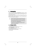
information about the model you are using. www.asrock.com/support/index.asp 1.1 Package Contents ASRock 890GMH/USB3 Motherboard (Micro ATX Form Factor: 9.6-in x 9.0-in, 24.4 cm x 22.9 cm) ASRock 890GMH/USB3 Quick Installation Guide ASRock 890GMH/USB3 Support CD 1 x Ultra ATA 66/100/133 IDE Ribbon - ASRock 890GMH/USB3 | User Manual - Page 6
, un-buffered memory (see CAUTION 3) - Max. capacity of system memory: 16GB (see CAUTION 4) - 1 x PCI Express 2.0 x16 slot (blue @ x16 mode) - 1 x PCI Express 2.0 x1 slot - 2 x PCI slots - Supports ATITM Hybrid CrossFireXTM - Integrated AMD Radeon HD 4290 graphics - DX10.1 class iGPU, Shader Model - ASRock 890GMH/USB3 | User Manual - Page 7
LAN Port with LED (ACT/LINK LED and SPEED LED) - HD Audio Jack: Rear Speaker/Central/Bass/Line in/ Front Speaker/Microphone (see CAUTION 6) - 1 x USB 3.0 port by Fresco FL1000G, supports USB 3.0 up to 5Gb/s - 5 x Serial ATAII 3.0Gb/s connectors, support RAID (RAID 0, RAID 1, RAID 10 and JBOD), NCQ - ASRock 890GMH/USB3 | User Manual - Page 8
OC Tuner (see CAUTION 8) - Intelligent Energy Saver (see CAUTION 9) - Instant Boot - ASRock Instant Flash (see CAUTION 10) - ASRock OC DNA (see CAUTION 11) - ASRock AIWI (see CAUTION 12) - ASRock APP Charger (see CAUTION 13) - Hybrid Booster: - CPU Frequency Stepless Control (see CAUTION - ASRock 890GMH/USB3 | User Manual - Page 9
installation guide of memory modules on page 16 for proper installation. 3. Whether 1800/1600MHz memory speed is supported depends Guide" on page 29 to adjust your SATAII hard disk drive to SATAII mode. You can also connect SATA hard disk to SATAII connector directly. 8. It is a user-friendly ASRock - ASRock 890GMH/USB3 | User Manual - Page 10
menu to access ASRock Instant Flash. Just launch this tool and save the new BIOS file to your USB flash drive, floppy disk or hard drive, then you can to do is just to install the ASRock AIWI utility either from ASRock official website or ASRock software support CD to your motherboard, and also - ASRock 890GMH/USB3 | User Manual - Page 11
15. While CPU overheat is detected, the system will automatically shutdown. Before you resume the system, please check if the CPU fan on the motherboard functions properly and unplug the power cord, then plug it back again. To improve heat dissipation, remember to spray thermal grease between the - ASRock 890GMH/USB3 | User Manual - Page 12
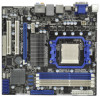
RJ-45 LAN USB 2.0: USB0 USB 3.0: USB1 eSATA1 USB 2.0 T: USB4 B: USB5 1 USB_PW2 LAN PCIE1 890GMH/USB3 AMD 890GX PCI Slots (PCI1-2) 13 USB 2.0 Header (USB8_9, Blue) 31 PCI Express 2.0 x16 Slot (PCIE2; Blue) 14 Southbridge Controller 32 PCI Express 2.0 x1 Slot (PCIE1; White) 15 SPI Flash - ASRock 890GMH/USB3 | User Manual - Page 13
) 12 USB 3.0 Port (USB1) 13 eSATAII Port (eSATA1) 14 VGA/HDMI Port 15 VGA/DVI-D Port 16 PS/2 Keyboard Port (Purple) * There are two LED next to the LAN port. Please refer to the table below for the LAN port LED indications. LAN Port LED Indications Activity/Link LED SPEED LED Status - ASRock 890GMH/USB3 | User Manual - Page 14
2. Installation This is a Micro ATX Form Factor (9.6-in x 9.0-in, 24.4 cm x 22.9 cm) motherboard. Before you install the motherboard, study the configuration of your chassis to ensure that the motherboard fits into it. Pre-installation Precautions Take note of the following precautions before you - ASRock 890GMH/USB3 | User Manual - Page 15
each other. Then connect the CPU fan to the CPU FAN connector (CPU_FAN1, see Page 12, No. 2). For proper installation, please kindly refer to the instruction manuals of the CPU fan and the heatsink. 15 - ASRock 890GMH/USB3 | User Manual - Page 16
Modules (DIMM) This motherboard provides four 240-pin DDR3 (Double Data Rate 3) DIMM slots, and supports Dual Channel Memory Technology. For dual channel configuration, you always need to install identical (the same brand, speed, size and chip-type) DDR3 DIMM pair in the slots of the same color. In - ASRock 890GMH/USB3 | User Manual - Page 17
Installing a DIMM Please make sure to disconnect power supply before adding or removing DIMMs or the system components. Step 1. Step 2. Unlock a DIMM slot by pressing the retaining clips outward. Align a DIMM on the slot such that the notch on the DIMM matches the break on the slot. notch break - ASRock 890GMH/USB3 | User Manual - Page 18
slot; White) is used for PCI Express cards with x1 lane width cards, such as Gigabit LAN card and SATA2 card. PCIE2 (PCIE x16 slot; Blue) is used for PCI Express x16 lane width graphics cards. Installing an expansion card Step 1. Before installing the expansion card, please make sure that the power - ASRock 890GMH/USB3 | User Manual - Page 19
of dual monitor feature without installing any add-on VGA card to this motherboard. This motherboard also provides independent display controllers for DVI-D, D-Sub and HDMI to support dual VGA output so that DVI-D, D-sub and HDMI can drive same or different display contents. To enable dual monitor - ASRock 890GMH/USB3 | User Manual - Page 20
Surround Display Feature This motherboard supports surround display upgrade. With the internal VGA output support (DVI-D, D-Sub and HDMI) and external add-on PCI Express VGA cards, you can easily enjoy the benefits of surround display feature. Please refer to the following steps to set up a surround - ASRock 890GMH/USB3 | User Manual - Page 21
function with this motherboard, you need to adopt the monitor that supports HDCP function as well. Therefore, you can enjoy the superior display quality with high-definition HDCP encryption contents. Please refer to below instruction for more details about HDCP function. What is HDCP? HDCP stands - ASRock 890GMH/USB3 | User Manual - Page 22
2.6 ATITM Hybrid CrossFireXTM Operation Guide This motherboard supports ATITM Hybrid CrossFireXTM feature. ATITM Hybrid 1GB Driver Support CD 8.70 Support CD 8.70 Support CD 8.70 Enjoy the benefit of ATITM Hybrid CrossFireXTM Step 1. Install one compatible PCI Express graphics card to PCIE2 - ASRock 890GMH/USB3 | User Manual - Page 23
Step 7. Double-click "ATI Catalyst Control Center". Click "View", click "CrossFireTM", and then select the option "Enable CrossFireTM". View CrossFireTM Enable CrossFireTM Step 8. Click "Yes" to continue. Step 9. Click "OK" to save your change. Step 10. Reboot your system. Then you can freely - ASRock 890GMH/USB3 | User Manual - Page 24
/45 +5V +5V_DUAL wake up events. Note: To select +5V_DUAL, it requires 2 Amp and higher standby current provided by power supply. When you select +5V_DUAL, USB devices can wake up the system under S3 (Suspend to RAM) state. USB_PW1 (see p.12, No. 9) 1_2 +5V 2_3 +5VSB Short pin2, pin3 to - ASRock 890GMH/USB3 | User Manual - Page 25
devices 80-conductor ATA 66/100/133 cable Note: Please refer to the instruction of your IDE device vendor for the details. Serial ATAII Connectors These five Serial ATAII (SATAII) (SATAII_1 (PORT 0): connectors support SATAII see p.12, No. 20) or SATA hard disk for internal (SATAII_2 (PORT - ASRock 890GMH/USB3 | User Manual - Page 26
allows convenient connection and control of audio devices. 1. High Definition Audio supports Jack Sensing, but the panel wire on the chassis must support HDA to function correctly. Please follow the instruction in our manual and chassis manual to install your system. 2. If you use AC'97 audio panel - ASRock 890GMH/USB3 | User Manual - Page 27
4 FAN_SPEED_CONTROL match the black wire to the ground pin. Though this motherboard provides 4-Pin CPU fan (Quiet Fan) support, the 3-Pin CPU fan still can work successfully even without the fan speed control function. If you plan to connect the 3-Pin CPU fan to the CPU fan connector on this - ASRock 890GMH/USB3 | User Manual - Page 28
p.12 No.27) RRXD1 DDTR#1 DDSR#1 CCTS#1 1 RRI#1 RRTS#1 GND TTXD1 DDCD#1 Please connect an ATX 12V power supply to this connector. This COM1 header supports a serial port module. 28 - ASRock 890GMH/USB3 | User Manual - Page 29
guide. Some default setting of SATAII hard disks may not be at SATAII mode, which operate with the best performance. In order to enable SATAII function, please follow the below instruction 's website for details: http://www.hitachigst.com/hdd/support/download.htm The above examples are just for your - ASRock 890GMH/USB3 | User Manual - Page 30
) Hard Disks Installation This motherboard adopts AMD SB710 south bridge chipset that supports Serial ATA (SATA) / Serial ATAII (SATAII) hard disks and RAID This section will guide you to install the SATA / SATAII hard disks. STEP 1: Install the SATA / SATAII hard disks into the drive bays of your - ASRock 890GMH/USB3 | User Manual - Page 31
Hot Plug and Hot Swap functions for SATA / SATAII Devices in RAID / AHCI mode. AMD SB710 south bridge chipset provides hardware support for Advanced Host controller Interface (AHCI), a new programming interface for SATA host controllers developed thru a joint industry effort. AHCI also provides - ASRock 890GMH/USB3 | User Manual - Page 32
into system properly. The latest SATA / SATAII driver is available on our support website: www.asrock.com 4. Make sure to use the SATA power cable & data cable, which are from our motherboard package. 5. Please follow below instructions step by step to reduce the risk of HDD crash or data loss - ASRock 890GMH/USB3 | User Manual - Page 33
the SATA / SATAII HDD. How to Hot Unplug a SATA / SATAII HDD: Points of attention, before you process the Hot Unplug: Please do follow below instruction sequence to process the Hot Unplug, improper procedure will cause the SATA / SATAII HDD damage and data loss. Step 1 Unplug SATA data cable from - ASRock 890GMH/USB3 | User Manual - Page 34
Guide To install the drivers to your system, please insert the support CD to your optical drive first. Then, the drivers compatible to your system can be auto-detected and listed on the support Driver Diskette. A. Insert the ASRock Support CD into your optical drive to boot your system. B. - ASRock 890GMH/USB3 | User Manual - Page 35
Operation Mode" to [RAID] first. Then, please set the RAID configuration by using the Windows RAID installation guide in the following path in the Support CD: .. \ RAID Installation Guide 2.14.2 Installing Windows® 7 / 7 64-bit / VistaTM / VistaTM 64-bit With RAID Functions If you want to install - ASRock 890GMH/USB3 | User Manual - Page 36
Mode" to [RAID] in BIOS first. Then, please set the RAID configuration by using the Windows RAID installation guide in the following path in the Support CD: .. \ RAID Installation Guide NOTE2. Currently, if you install Windows® 7 / 7 64-bit / VistaTM / VistaTM 64-bit on IDE HDDs and there are - ASRock 890GMH/USB3 | User Manual - Page 37
Using SATA / SATAII HDDs without NCQ and Hot Plug functions (IDE mode) STEP 1: Set up BIOS. A. Enter BIOS SETUP UTILITY Advanced screen Storage Configuration. B. Set the "SATA Operation Mode" option to [IDE]. STEP 2: Install Windows® XP / XP 64-bit OS on your system. 2.15.2 Installing - ASRock 890GMH/USB3 | User Manual - Page 38
This motherboard supports Untied Overclocking Technology, which means during overclocking, FSB enjoys better margin due to fixed PCI / PCIE Auto] to [CPU, PCIE, Async.]. Therefore, CPU FSB is untied during overclocking, but PCI / PCIE buses are in the fixed mode so that FSB can operate under a more - ASRock 890GMH/USB3 | User Manual - Page 39
SETUP UTILITY when you start up the computer. Please press or during the Power-On-Self-Test (POST) to enter the BIOS SETUP UTILITY, otherwise, POST will continue with its test routines. If you wish to enter the BIOS SETUP UTILITY after POST, restart the system by pressing + - ASRock 890GMH/USB3 | User Manual - Page 40
Exit System Overview System Time System Date [17:00:09] [Mon 08/23/2010] BIOS Version : 890GMH/USB3 P1.00 Processor Type : AMD Athlon(tm) II X4 620 Processor (64bit) Processor Speed : 2600MHz Microcode Update : 100F52/1000086 L1 Cache Size : 512KB L2 Cache Size : 2048KB Total Memory DDR3_A1 - ASRock 890GMH/USB3 | User Manual - Page 41
3.3 OC Tweaker Screen In the OC Tweaker screen, you can set up overclocking features. BIOS SETUP UTILITY Main OC Tweaker Advanced H/W Monitor Boot Security Exit EZ Overclocking Turbo 30 [Press Enter] Load Optimized CPU OC Setting [Press Enter] Load Optimized mGPU OC Setting [Press Enter] CPU - ASRock 890GMH/USB3 | User Manual - Page 42
It will display Processor Maximum Voltage for reference. Multiplier/Voltage Change This item is set to [Auto] by default. If it is set to [Manual], you may adjust the value of Processor Frequency and Processor Voltage. However, it is recommended to keep the default value for system stability. BIOS - ASRock 890GMH/USB3 | User Manual - Page 43
However, for safety and system stability, it is not recommended to adjust the value of this item. HT Bus Speed This feature allows you selecting Hyper-Transport bus speed. Configuration options: [Auto], [x1 200MHz] to [x10 2000MHz]. HT Bus Width This feature allows you selecting Hyper-Transport bus - ASRock 890GMH/USB3 | User Manual - Page 44
Memory Timing BIOS SETUP UTILITY OC Tweaker Memory Timing Power Down Enable Bank Interleaving Channel Interleaving [Disabled] [Auto] [HASH 2] CAS Latency (CL) 9 TRCD 12 TRP 12 TRAS 30 TRTP 5 TRRD 4 TWTR 5 TWR 10 TRC 33 TRWTWB 8 TRWTTO 7 TWRRD 2 [Auto] [Auto] [Auto] [Auto] - ASRock 890GMH/USB3 | User Manual - Page 45
TRRD Use this to adjust TRRD values. Configuration options: [Auto], [4CLK] to [7CLK]. The default value is [Auto]. TWTR Use this to adjust TWTR values. Configuration options: [Auto], [4CLK] to [7CLK]. The default value is [Auto]. TWR Use this to adjust TWR values. Configuration options: [Auto], [ - ASRock 890GMH/USB3 | User Manual - Page 46
to adjust values for CHB CS/ODT Setup feature. Configuration options: [Auto], [1/2CLK] and [1CLK]. The default value is [Auto]. CHA CKE Drive Use this to adjust values for CHA CKE Drive. Configuration options: [Auto], [1.00x], [1.25x], [1.50x] and [2.00x]. The default value is [Auto]. CHA CS/ODT - ASRock 890GMH/USB3 | User Manual - Page 47
values for CHA Processor ODT. Configuration options: [Auto], [240 ohms], [120 ohms] and [60 ohms]. The default value is [Auto]. CHB CKE Drive Use this to adjust values for CHB CKE Drive. Configuration options: [Auto], [1.00x], [1.25x], [1.50x] and [2.00x]. The default value is [Auto]. CHB CS/ODT - ASRock 890GMH/USB3 | User Manual - Page 48
Chipset Settings Onboard GPU Clock Override This allows you to enable or disable the Onboard GPU Clock Override feature. Onboard GPU Clock This option only appears when you enable "Onboard GPU Clock Override". The default value is [700]. mGPU Voltage Use this to select mGPU voltage. Configuration - ASRock 890GMH/USB3 | User Manual - Page 49
few clicks without preparing an additional floppy diskette or other complicated flash utility. Please be noted that the USB flash drive or hard drive must use FAT32/16/ 12 file system. If you execute ASRock Instant Flash utility, the utility will show the BIOS files and their respective information - ASRock 890GMH/USB3 | User Manual - Page 50
]. Configuration options: [Enabled] and [Disabled]. Enhance Halt State All processors support the Halt State (C1). The C1 state is supported through the native processor instructions HLT and MWAIT and requires no hardware support from the chipset. In the C1 power state, the processor maintains the - ASRock 890GMH/USB3 | User Manual - Page 51
HD Audio Select [Auto], [Enabled] or [Disabled] for the onboard HD Audio feature. If you select [Auto], the onboard HD Audio will be disabled when PCI Sound Card is plugged. Front Panel Select [Auto] or [Disabled] for the onboard HD Audio Front Panel. OnBoard Lan This allows you to enable or disable - ASRock 890GMH/USB3 | User Manual - Page 52
3.4.3 ACPI Configuration BIOS SETUP UTILITY Advanced ACPI Settings Suspend To RAM Check Ready Bit Away Mode Support Restore on AC / Power Loss Ring-In Power On PCI Devices Power On PS / 2 Keyboard Power On RTC Alarm Power On ACPI HPET Table [Auto] [Auto] [Disabled] [Power Off] [Disabled] [ - ASRock 890GMH/USB3 | User Manual - Page 53
We will use the "IDE1 Master" as the example in the following instruction, which can be applied to the configurations of "IDE1 Slave" as :Hard Disk :MAXTOR 6L080J4 :80.0 GB :Supported :16Sectors :4 :MultiWord DMA-2 :Ultra DMA-6 :Supported Type LBA/Large Mode Block (Multi-Sector Transfer) - ASRock 890GMH/USB3 | User Manual - Page 54
use of IDE device. [Auto]: Select [Auto] to automatically detect the hard disk drive. After selecting the hard disk information into BIOS, use a disk utility, such as timing. DMA Mode DMA capability allows the improved transfer-speed and data-integrity for compatible IDE devices. S.M.A.R.T. Use - ASRock 890GMH/USB3 | User Manual - Page 55
expansion cards' specifications require other settings. PCI IDE BusMaster Use this item to enable or disable the PCI IDE BusMaster feature. 3.4.6 Floppy Configuration In this section, you may configure the type of your floppy drive. BIOS SETUP UTILITY Advanced Floppy Configuration Floppy A [1.44 - ASRock 890GMH/USB3 | User Manual - Page 56
Save and Exit Exit v02.54 (C) Copyright 1985-2003, American Megatrends, Inc. OnBoard Floppy Controller Use this item to enable or disable floppy drive controller. Serial Port Address Use this item to set the address for the onboard serial port or disable it. Configuration options: [Disabled], [3F8 - ASRock 890GMH/USB3 | User Manual - Page 57
Controller Use this item to enable or disable the use of USB controller. USB 2.0 Support Use this item to enable or disable the USB 2.0 support. Legacy USB Support Use this option to select legacy support for USB devices. There are four configuration options: [Enabled], [Auto], [Disabled] and [BIOS - ASRock 890GMH/USB3 | User Manual - Page 58
monitor the status of the hardware on your system, including the parameters of the CPU temperature, motherboard temperature, CPU fan speed, chassis fan speed, and the critical voltage. BIOS SETUP UTILITY Main OC Tweaker Advanced H/W Monitor Boot Security Exit Hardware Health Event Monitoring CPU - ASRock 890GMH/USB3 | User Manual - Page 59
during System Boot. 1st Boot Device 2nd Boot Device 3rd Boot Device 4th Boot Device Hard Disk Drives Removable Drives CD/DVD Drives [1st Floppy Device] [HDD: PM - HDS722580VL] [CD / DVD: 3S - CD - ROM C] [USB] Select Screen Select Item Enter Go to Sub Screen F1 General Help F9 Load Defaults F10 - ASRock 890GMH/USB3 | User Manual - Page 60
to select logo in POST screen. This option only appears when you enable the option "Full Screen Logo". Configuration options: [Auto], [EuP], [Scenery] and [ASRock]. The default value is [Auto]. Boot From Onboard LAN Use this item to enable or disable the Boot From Onboard LAN feature. Boot Up Num - ASRock 890GMH/USB3 | User Manual - Page 61
3.8 Exit Screen BIOS SETUP UTILITY Main OC Tweaker Advanced H/W Monitor Boot Security Exit Exit Options Save Changes and Exit Discard Changes and Exit Discard Changes Load BIOS Defaults Load Performance Setup Default (IDE/SATA) Load Power Saving Setup Default Exit system setup after saving the - ASRock 890GMH/USB3 | User Manual - Page 62
with the motherboard contains necessary drivers and useful utilities that enhance the motherboard features. 4.2.1 Running The Support CD To begin using the support CD, insert the CD into your CD-ROM drive. The CD automatically displays the Main Menu if "AUTORUN" is enabled in your computer. If the
-
 1
1 -
 2
2 -
 3
3 -
 4
4 -
 5
5 -
 6
6 -
 7
7 -
8
-
9
-
10
-
11
-
12
-
13
-
14
-
15
-
16
-
17
-
18
-
19
-
20
-
21
-
22
-
23
-
24
-
25
-
26
-
27
-
28
-
29
-
30
-
31
-
32
-
33
-
34
-
35
-
36
-
37
-
38
-
39
-
40
-
41
-
42
-
43
-
44
-
45
-
46
-
47
-
48
-
49
-
50
-
51
-
52
-
53
-
54
-
55
-
56
-
57
-
58
-
59
-
60
-
61
-
62
 |
 |

1
890GMH/USB3
User Manual
Version 1.0
Published August 2010
Copyright©2010 ASRock INC. All rights reserved.