ASRock 890GX Extreme3 User Manual
ASRock 890GX Extreme3 Manual
 |
View all ASRock 890GX Extreme3 manuals
Add to My Manuals
Save this manual to your list of manuals |
ASRock 890GX Extreme3 manual content summary:
- ASRock 890GX Extreme3 | User Manual - Page 1
890GX Extreme3 User Manual Version 1.1 Published March 2010 Copyright©2010 ASRock INC. All rights reserved. 1 - ASRock 890GX Extreme3 | User Manual - Page 2
commitment by ASRock. ASRock assumes no responsibility for any errors or omissions that may appear in this manual. With respect to the contents of this manual, ASRock does not , USA ONLY The Lithium battery adopted on this motherboard contains Perchlorate, a toxic substance controlled in Perchlorate - ASRock 890GX Extreme3 | User Manual - Page 3
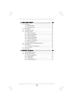
36 2.11 Dr. Debug 37 2.12 HDMI_SPDIF Header Connection Guide 40 2.13 Serial ATA3 (SATA3) Hard Disks Installation 41 2.14 Hot Plug and Hot Swap Functions for SATA3 HDDs 41 2.15 SATA3 HDD Hot Plug Feature and Operation Guide 42 2.16 Driver Installation Guide 44 2.17 Installing Windows® 7 / 7 64 - ASRock 890GX Extreme3 | User Manual - Page 4
BIOS Menu Bar 48 3.1.2 Navigation Keys 49 3.2 Main Screen 49 3.3 OC Tweaker Screen 50 3.4 Advanced Screen 58 3.4.1 CPU Screen 71 4 . Software Support 72 4.1 Install Operating System 72 4.2 Support CD Information 72 4.2.1 Running Support CD 72 4.2.2 Drivers Menu 72 4.2.3 Utilities Menu - ASRock 890GX Extreme3 | User Manual - Page 5
guide to BIOS setup and information of the Support CD. Because the motherboard specifications and the BIOS software might be updated, the content of this manual will be subject to change without notice. In case any modifications of this manual occur, the updated version will be available on ASRock - ASRock 890GX Extreme3 | User Manual - Page 6
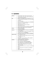
1.2 Specifications Platform CPU Chipset Memory Expansion Slot Graphics - ATX Form Factor: 12.0-in x 9.6-in, 30.5 cm x 24.4 cm - All Solid Capacitor design (100% Japan-made high-quality Conductive Polymer Capacitors) - Support for Socket AM3 processors: AMD PhenomTM II X4 / X3 / X2 (except 920 / - ASRock 890GX Extreme3 | User Manual - Page 7
Content Protection - DAC with 110dB dynamic range (VIA® VT2020 Audio Codec) - Premium Blu-ray audio support - PCIE x1 Gigabit LAN 10/100/1000 Mb/s - Realtek RTL8111E - Supports Wake-On-LAN - Supports LAN Cable Detection I/O Panel - 1 x PS/2 Keyboard Port - 1 x VGA/D-Sub Port - 1 x VGA/DVI-D Port - ASRock 890GX Extreme3 | User Manual - Page 8
BIOS - Supports "Plug and Play" - ACPI 1.1 Compliance Wake Up Events - Supports jumperfree - SMBIOS 2.3.1 Support - CPU, VCCM, NB, SB Voltage Multi-adjustment Support CD - Drivers, Utilities, AntiVirus Software (Trial Version), AMD OverDriveTM Utility, AMD Live! Explorer, AMD Fusion, ASRock - ASRock 890GX Extreme3 | User Manual - Page 9
installation. 4. Whether 1600MHz memory speed is supported depends on the AM3 CPU you adopt. If you want to adopt DDR3 1600 memory module on this motherboard, please refer to the memory support list on our website for the compatible memory modules. ASRock website http://www.asrock.com 5. Due to the - ASRock 890GX Extreme3 | User Manual - Page 10
of Intelligent Energy Saver. ASRock website: http://www.asrock.com 11. ASRock Instant Flash is a BIOS flash utility embedded in Flash ROM. This convenient BIOS update tool allows you to update system BIOS without entering operating systems first like MS-DOS or Windows®. With this utility, you - ASRock 890GX Extreme3 | User Manual - Page 11
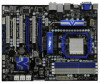
memory 128MB PCI Express 2.0 Super I/O RoHS PCI1 Six-Core CPU Ready 8Mb BIOS NEC USB 3.0 PCIE3 890GX Extreme3 PCI2 CMOS BATTERY ErP/EuP Ready AMD SB850 Chipset AUDIO SATA3_5_6 Dr. Debug SPEAKER1 1 34 33 32 31 30 29 28 27 26 25 24 23 22 21 FSB2.6GHz 140W CPU 30.5cm (12.0-in) 9 10 11 - ASRock 890GX Extreme3 | User Manual - Page 12
Port 8 Line In (Light Blue) ** 9 Front Speaker (Lime) 15 14 13 12 11 10 Microphone (Pink) 11 USB 3.0 Port (USB01) 12 IEEE 1394 Port (IEEE 1394) 13 accordance with the type of speaker you use. TABLE for Audio Output Connection Audio Output Channels Front Speaker Rear Speaker Central / Bass Line - ASRock 890GX Extreme3 | User Manual - Page 13
-Streaming function, you need to connect a front panel audio cable to the front panel audio header. After restarting your computer, you will find "VIA HD Audio Deck" tool on your system. Please follow below instructions according to the OS you install. For Windows® XP / XP 64-bit OS: Please click - ASRock 890GX Extreme3 | User Manual - Page 14
, peripherals, and/or components. 1. Unplug the power cord from the wall socket before touching any component. 2. To avoid damaging the motherboard components due to static electricity, NEVER place your motherboard directly on the carpet or the like. Also remember to use a grounded wrist strap - ASRock 890GX Extreme3 | User Manual - Page 15
Socker Corner Small Triangle STEP 2 / STEP 3: Match The CPU Golden Triangle To The Socket Corner Small Triangle STEP 4: Push Down And Lock The Socket Lever 2.2 Installation of CPU Fan and Heatsink After you install the CPU into this motherboard, it is necessary to install a larger heatsink and - ASRock 890GX Extreme3 | User Manual - Page 16
slots; see p.11 No.8), so that Dual Channel Memory Technology can be activated. This motherboard also allows you to install four DDR3 DIMMs for dual in all four slots. 1. If you want to install two memory modules, for optimal compatibility and reliability, it is recommended to install them in the - ASRock 890GX Extreme3 | User Manual - Page 17
matches the break on the slot. notch break notch break The DIMM only fits in one correct orientation. It will cause permanent damage to the motherboard and the DIMM if you force the DIMM into the slot at incorrect orientation. Step 3. Firmly insert the DIMM into the slot until the retaining - ASRock 890GX Extreme3 | User Manual - Page 18
. PCIE2 / PCIE3 (PCIE x16 slot; Blue) is used for PCI Express x16 lane width graphics cards, or used to install PCI Express graphics cards to support CrossFireXTM function. PCIE4 (PCIE x16 slot; White) is used for PCI Express x1 lane width cards, such as Gigabit LAN card, SATA2 card, etc, or - ASRock 890GX Extreme3 | User Manual - Page 19
HDMI monitor cable to HDMI port on the I/O panel. VGA/D-Sub port VGA/DVI-D port HDMI port 2. If you have installed onboard VGA driver from our support CD to your system already, you can freely enjoy the benefits of dual monitor function after your system boots. If you haven't installed onboard VGA - ASRock 890GX Extreme3 | User Manual - Page 20
memory. If you do not adjust the BIOS setup, the default value of "Share Memory", [Auto], will disable VGA/D-Sub function when the add-on VGA card is inserted to this motherboard. 4. Install the onboard VGA driver the number 2. D. Click "Extend my Windows desktop onto this monitor". E. Right-click - ASRock 890GX Extreme3 | User Manual - Page 21
Windows supported on this motherboard. To use HDCP function with this motherboard, you need to adopt the monitor that supports HDCP function as well. Therefore, you can enjoy the superior display quality with high-definition HDCP encryption contents. Please refer to below instruction compatible - ASRock 890GX Extreme3 | User Manual - Page 22
supported with Windows® XP with Service Pack 2 / VistaTM / 7 OS. 3-way CrossFireXTM and Quad CrossFireXTM feature are supported with Windows® VistaTM / 7 OS only. Please check AMD website for ATITM CrossFireXTM driver updates ATITM graphics card manuals for detailed installation guide. Step 1. - ASRock 890GX Extreme3 | User Manual - Page 23
Bridge is provided with the graphics card you purchase, not bundled with this motherboard. Please refer to your graphics card vendor for details.) CrossFire Bridge or Step 3. Connect the DVI monitor cable to the DVI connector on the Radeon graphics card on PCIE2 slot. (You may use the DVI - ASRock 890GX Extreme3 | User Manual - Page 24
Bridge to connect Radeon graphics cards on PCIE3 and PCIE4 slots. (CrossFireTM Bridge is provided with the graphics card you purchase, not bundled with this motherboard. Please refer to your graphics card vendor for details.) 24 - ASRock 890GX Extreme3 | User Manual - Page 25
CrossFireTM Bridge Step 5. Connect the DVI monitor cable to the DVI connector on the Radeon graphics card on PCIE2 slot. (You may use the DVI to D-Sub adapter to convert the DVI connector to D-Sub interface, and then connect the D-Sub monitor cable to the DVI to D-Sub adapter.) 25 - ASRock 890GX Extreme3 | User Manual - Page 26
for ATITM driver updates. Step 3. Step 4. Step 5. Install the required drivers to your system. For Windows® XP OS: A. ATITM recommends Windows® XP Service Pack 2 or higher to be installed (If you have Windows® XP Service Pack 2 or higher installed in your system, there is no need to download it - ASRock 890GX Extreme3 | User Manual - Page 27
is used only for identification or explanation and to the owners' benefit, without intent to infringe. * For further information of ATITM CrossFireXTM technology, please check AMD website for updates and details. 27 - ASRock 890GX Extreme3 | User Manual - Page 28
series graphics processor and a motherboard based on an AMD 890GX integrated chipset, all operating in a Windows® VistaTM / 7 environment. Please refer to below PCI Express graphics card support list for ATITM Hybrid CrossFireXTM. For the future update of more compatible PCI Express graphics cards - ASRock 890GX Extreme3 | User Manual - Page 29
8. Click "Yes" to continue. Step 9. Click "OK" to save your change. Step 10. Reboot your system. Then you can freely enjoy the benefit of HybridTM CrossFireXTM feature. * Hybrid * For further information of ATITM Hybrid CrossFireXTM technology, please check AMD website for up dates and details. 29 - ASRock 890GX Extreme3 | User Manual - Page 30
USB devices can wake up the system under S3 (Suspend to RAM) state. To support ErP/EuP requirement, please set this jumper to +5V. USB_PW3 (see p.11, No clear the CMOS right after you update the BIOS. If you need to clear the CMOS when you just finish updating the BIOS, you must boot up the - ASRock 890GX Extreme3 | User Manual - Page 31
will not function. Either end of the SATA data cable can be connected to the SATA3 hard disk or the SATA3 connector on this motherboard. Serial ATA (SATA) Power Cable (Optional) connect to the SATA HDD power connector connect to the power supply eSATA3 Bracket (Optional) Please connect the - ASRock 890GX Extreme3 | User Manual - Page 32
GND DUMMY 1 GND P+10 P-10 USB_PWR USB_PWR P-9 P+9 Audio Header (9-pin HD_AUDIO1) (see p.11, No. 34) IRTX +5V DUMMY 1 GND IRRX GND PRESENCE# MIC_RET OUT_RET 1 OUT2_L J_SENSE OUT2_R MIC2_R MIC2_L Besides four default USB 2.0 ports on the I/O panel, there are four USB 2.0 headers on this motherboard - ASRock 890GX Extreme3 | User Manual - Page 33
support HDA to function correctly. Please follow the instruction in our manual and chassis manual to install your system. 2. If you use AC'97 audio panel, please install it to the front panel audio for HD audio panel only. You don't need to connect them for AC'97 audio panel. E. Enter BIOS Setup - ASRock 890GX Extreme3 | User Manual - Page 34
speed control function. If you plan to connect the 3-Pin CPU fan to the CPU fan connector on this motherboard, please connect it to Pin 1-3. Pin 1-3 Connected 3-Pin Fan Installation ATX Power Connector (24-pin ATXPWR1) (see p.11 No. 10) 12 24 Please connect an ATX power supply to this connector - ASRock 890GX Extreme3 | User Manual - Page 35
+5V HDMI_SPDIF Cable (Optional) C B A HDMI_SPDIF header, providing SPDIF audio output to HDMI VGA card, allows the system to con nect HDMI Digital the black end (A) of HDMI_SPDIF cable to the HDMI_SPDIF header on the motherboard. Then connect the white end (B or C) of HDMI_SPDIF cable to the - ASRock 890GX Extreme3 | User Manual - Page 36
2.10 Smart Switches This motherboard has three smart switches: power switch, reset switch and clear CMOS switch, allowing users to quickly turn on/off or reset the system or clear - ASRock 890GX Extreme3 | User Manual - Page 37
2.11 Dr. Debug Dr. Debug is used to provide code information, which makes troubleshooting even easier. Please see the diagrams below for reading the Dr. Debug codes. The Bootblock initialization code sets up the chipset, memory and other components before system memory is available. The following - ASRock 890GX Extreme3 | User Manual - Page 38
cache for boot strap proccessor Early CPU Init Exit Initializes the 8042 compatible Key Board Controller. Detects the presence of PS/2 mouse. Detects the presence of Keyboard in KBC port. Testing and initialization of different Input Devices. Also, update the Kernel Variables. Traps the INT09h - ASRock 890GX Extreme3 | User Manual - Page 39
CPU, etc.) successfully installed in the system and update the BDA, EBDA, etc. 50 Programming the memory hole or any kind of implementation that needs an adjustment in system RAM size if needed. 52 Updates CMOS memory size from memory found in memory test. Allocates memory for Extended BIOS - ASRock 890GX Extreme3 | User Manual - Page 40
compatible digital audio or video monitor, such as a digital television (DTV). A complete HDMI system requires a HDMI VGA card and a HDMI ready motherboard with a HDMI_SPDIF header. This motherboard VGA card. Please refer to the VGA card user manual for connector usage in advance. Step 4. Step 5. - ASRock 890GX Extreme3 | User Manual - Page 41
hard disk. 2.14 Hot Plug Function for SATA3 HDDs This motherboard supports Hot Plug and Hot Swap functions for SATA3 in AHCI mode. AMD SB850 chipset provides hardware support for Advanced Host controller Interface (AHCI), a new programming interface for SATA host controllers developed thru a joint - ASRock 890GX Extreme3 | User Manual - Page 42
in the product spec on our website: www.asrock.com 2. Make sure your SATA3 HDD can support Hot Plug function from your dealer or HDD user manual. The SATA3 HDD, which cannot support Hot Plug function, will be damaged under the Hot Plug operation. 3. Please make sure the SATA3 driver is installed - ASRock 890GX Extreme3 | User Manual - Page 43
cable to (White) to the power supply 1x4-pin cable. the motherboard's SATA3 connector. SATA power cable 1x4-pin power connector (White) Step attention, before you process the Hot Unplug: Please do follow below instruction sequence to process the Hot Unplug, improper procedure will cause the SATA3 - ASRock 890GX Extreme3 | User Manual - Page 44
first. Then, the drivers compatible to your system can be auto-detected and listed on the support CD driver page. Please follow the order from up to bottom side to install those required drivers. Therefore, the drivers you install can work properly. 2.17 Installing Windows® 7 / 7 64-bit / VistaTM - ASRock 890GX Extreme3 | User Manual - Page 45
refer to the BIOS RAID installation guide part of the document in the following path in the Support CD: .. \ RAID Installation Guide STEP 3: Make a SATA3 Driver Diskette. Make a SATA3 driver diskette by following section 2.17.1 step 2 on page 44. STEP 4: Install Windows® 7 / 7 64-bit / VistaTM - ASRock 890GX Extreme3 | User Manual - Page 46
OS on your system. At the beginning of Windows® setup, press F6 to install a third-party AHCI driver. When prompted, insert the SATA3 driver diskette containing the AMD AHCI driver. After reading the floppy disk, the driver will be presented. Select the driver to install according to the OS you - ASRock 890GX Extreme3 | User Manual - Page 47
steps. Using SATA3 HDDs with NCQ and Hot Plug functions (AHCI mode) STEP 1: Set Up BIOS. A. Enter BIOS SETUP UTILITY Advanced screen Storage Configuration. B. Set the "SATA Operation Mode" option to [AHCI]. STEP 2: Install Windows® 7 / 7 64-bit / VistaTM / VistaTM 64-bit OS on your system - ASRock 890GX Extreme3 | User Manual - Page 48
Memory on the motherboard stores the BIOS SETUP UTILITY. You may run the BIOS SETUP UTILITY when you start up the computer. Please press or during the Power-On-Self-Test (POST) to enter the BIOS on. Because the BIOS software is constantly being updated, the following BIOS setup screens and - ASRock 890GX Extreme3 | User Manual - Page 49
] [Tue 03/02/2010] BIOS Version : 890GX Extreme3 P1.00 Processor Type : AMD Phenom(tm) II X2 555 Processor (64bit) Processor Speed : 3200MHz Microcode Update : 100F43/10000B6 L1 Cache Size : 256KB L2 Cache Size : 2048KB L3 Cache Size : 6144KB Total Memory DDR3_A1 DDR3_A2 DDR3_B1 DDR3_B2 : 1024MB - ASRock 890GX Extreme3 | User Manual - Page 50
Boot Failure Guard Count ASRock UCC CPU Active Core Control [Auto] [200] [Auto] [100] [Auto] [Enabled] [3] [Disabled] [All Cores] Processor Maximum Frequency x10.5 2100 MHZ North Bridge Maximum Frequency x9.0 1800 MHz Overclocking may cause damage to your CPU and motherboard. It should be done - ASRock 890GX Extreme3 | User Manual - Page 51
, which means you can enjoy the upgrade CPU performance with a better price. Please be noted that UCC feature is supported with AM3 CPU only, and in addition, not every AM3 CPU can support this function because some CPU's hidden core may be malfunctioned. CPU Active Core Control This allows you to - ASRock 890GX Extreme3 | User Manual - Page 52
not recommended to adjust the value of this item. CPU Voltage It allows you to adjust the value of CPU voltage. However, for safety and system stability, it : [Auto], [8 Bit] and [16 Bit]. Memory Configuration Memory Clock This item can be set by the code using [Auto]. You can set one of the - ASRock 890GX Extreme3 | User Manual - Page 53
Memory Timing BIOS SETUP UTILITY OC Tweaker Memory Timing Memory Controller Mode Power Down Enable Bank Interleaving Channel Interleaving CAS Latency (CL) 9 TRCD 12 TRP 12 TRAS 30 TRTP 5 TRRD 4 TWTR 5 TWR 10 TRC 33 TRWTWB 8 TRWTTO 7 TWRRD 2 [Unganged] [Disabled] [Auto] [ - ASRock 890GX Extreme3 | User Manual - Page 54
TRRD Use this to adjust TRRD values. Configuration options: [Auto], [4CLK] to [7CLK]. The default value is [Auto]. TWTR Use this to adjust TWTR values. Configuration options: [Auto], [4CLK] to [7CLK]. The default value is [Auto]. TWR Use this to adjust TWR values. Configuration options: [Auto], [ - ASRock 890GX Extreme3 | User Manual - Page 55
CHA ADDR/CMD Setup Use this to adjust values for CHA ADDR/CMD Setup feature. Configuration options: [Auto], [1/2CLK] and [1CLK]. The default value is [Auto]. CHA CS/ODT Delay Use this to adjust values for CHA CS/ODT Delay feature. Configuration options: [Auto], [No Delay], [1/64CLK] to [31/64CLK]. - ASRock 890GX Extreme3 | User Manual - Page 56
CHA Processor ODT Use this to adjust values for CHA Processor ODT. Configuration options: [Auto], [240 ohms], [120 ohms] and [60 ohms]. The default value is [Auto]. CHB CKE Drive Use this to adjust values for CHB CKE Drive. Configuration options: [Auto], [1.00x], [1.25x], [1.50x] and [2.00x]. The - ASRock 890GX Extreme3 | User Manual - Page 57
SidePort Voltage Use this to select SidePort voltage. Configuration options: [Auto], [1.50V] and [1.80V]. The default value is [Auto]. CPU VDDA Voltage Use this to select CPU VDDA voltage. Configuration options: [Auto], [2.56V] and [2.70V]. The default value is [Auto]. PCIE VDDA Voltage Use this to - ASRock 890GX Extreme3 | User Manual - Page 58
section may cause the system to malfunction. ASRock Instant Flash ASRock Instant Flash is a BIOS flash utility embedded in Flash ROM. This convenient BIOS update tool allows you to update system BIOS without entering operating systems first like MS-DOS or Windows®. Just launch this tool and save - ASRock 890GX Extreme3 | User Manual - Page 59
Secure Virtual Machine Enhanced Halt State L3 Cache Allocation BIOS SETUP UTILITY [Auto] [Enabled] [Disabled] [Auto] Enabling this function may reduce CPU voltage and memory freq., and lead to system stability or compatibility issue with some memory modules or power supplies. Please set this item - ASRock 890GX Extreme3 | User Manual - Page 60
3.4.2 Chipset Configuration BIOS SETUP UTILITY Advanced Chipset Settings Onboard HD Audio Front Panel OnBoard Lan Dr. LAN Link speed : 10Mbps Onboard IEEE 1394 Primary Graphics Adapter Internal Graphics Mode UMA Frame Buffer Size Onboard HDMI HD Audio Surround View [Auto] [Auto] [Enabled] [ - ASRock 890GX Extreme3 | User Manual - Page 61
Onboard HDMI HD Audio This allows you to enable or disable the onboard HDMI HD Audio in AMD 890GX. If you use Dual-link DVI monitor, please set this item to [Disabled]. Surround View This allows you to enable or disable the Surround View feature or Hybrid CrossFireXTM feature. 61 - ASRock 890GX Extreme3 | User Manual - Page 62
3.4.3 ACPI Configuration BIOS SETUP UTILITY Advanced ACPI Settings Suspend To RAM Check Ready Bit Away Mode Support Restore on AC / or disable the feature Check Ready Bit. Away Mode Support Use this item to enable or disable Away Mode support under Windows® XP Media Center OS. The default value is - ASRock 890GX Extreme3 | User Manual - Page 63
suggested to install SATA ODD driver on SATA5 port. AMD AHCI BIOS ROM Use this item to enable or disable AMD AHCI BIOS ROM. This option appears only when you set "SATA Operation Mode" to [AHCI]. The default value is SATA6 port is used internally, not eSATA, please set [Auto] for SATA3 support. 63 - ASRock 890GX Extreme3 | User Manual - Page 64
BIOS SETUP UTILITY Advanced SATA3_1 Master Device Vendor Size LBA Mode Block Mode PIO Mode Async DMA Ultra DMA S.M.A.R.T. :Hard Disk :MAXTOR 6L080J4 :80.0 GB :Supported :16Sectors :4 :MultiWord DMA-2 :Ultra DMA-6 :Supported MB under DOS and Windows; for Netware and UNIX compatible IDE devices. 64 - ASRock 890GX Extreme3 | User Manual - Page 65
], [Enabled]. 32Bit Data Transfer Use this item to enable 32-bit access to maximize the IDE hard disk data transfer rate. 3.4.5 PCIPnP Configuration BIOS SETUP UTILITY Advanced Advanced PCI / PnP Settings PCI Latency Timer PCI IDE BusMaster [32] [Enabled] Value in units of PCI clocks for PCI - ASRock 890GX Extreme3 | User Manual - Page 66
SETUP UTILITY Advanced Configure Super IO Chipset Serial Port Address Infrared Port Address PS/2 Port Type [3F8 / IRQ4] [Disabled] [Auto] Allow BIOS to Select Serial Port Base Addresses. +F1 F9 F10 ESC Select Screen Select Item Change Option General Help Load Defaults Save and Exit Exit v02 - ASRock 890GX Extreme3 | User Manual - Page 67
these four options: [Enabled] - Enables support for legacy USB. [Auto] - Enables legacy support if USB devices are connected. [Disabled] - USB devices are not allowed to use under legacy OS and BIOS setup when [Disabled] is selected. If you have USB compatibility issue, it is recommended to select - ASRock 890GX Extreme3 | User Manual - Page 68
of the CPU temperature, motherboard temperature, CPU fan speed, chassis fan speed, and the critical voltage. BIOS SETUP UTILITY allows you to set the chassis fan 2 speed. Configuration options: [Full On] and [Manual mode]. The default is value [Full On]. Chassis Fan 3 Setting This allows you to - ASRock 890GX Extreme3 | User Manual - Page 69
F1 General Help F9 Load Defaults F10 Save and Exit ESC Exit v02.54 (C) Copyright 1985-2005, American Megatrends, Inc. 3.6.1 Boot Settings Configuration BIOS SETUP UTILITY Boot Boot Settings Configuration Full Screen Logo AddOn ROM Display Boot Logo Boot From Onboard LAN Bootup Num-Lock [Enabled - ASRock 890GX Extreme3 | User Manual - Page 70
the option "Full Screen Logo". Configuration options: [Auto], [EuP], [Scenery] and [ASRock]. The default value is [Auto]. Currently, the option [Auto] is set to system. For the user password, you may also clear it. BIOS SETUP UTILITY Main OC Tweaker Advanced H/W Monitor Boot Security Exit Security - ASRock 890GX Extreme3 | User Manual - Page 71
message, "Discard changes?" Select [OK] to discard all changes. Load BIOS Defaults Load BIOS default values for all the setup questions. F9 key can be used for this operation. Load Performance Setup AHCI Mode This performance setup AHCI mode may not be compatible with all system configurations. If - ASRock 890GX Extreme3 | User Manual - Page 72
install the necessary drivers to activate the devices. 4.2.3 Utilities Menu The Utilities Menu shows the applications software that the motherboard supports. Click on a specific item then follow the installation wizard to install it. 4.2.4 Contact Information If you need to contact ASRock or want to
-
 1
1 -
 2
2 -
 3
3 -
 4
4 -
 5
5 -
 6
6 -
 7
7 -
8
-
9
-
10
-
11
-
12
-
13
-
14
-
15
-
16
-
17
-
18
-
19
-
20
-
21
-
22
-
23
-
24
-
25
-
26
-
27
-
28
-
29
-
30
-
31
-
32
-
33
-
34
-
35
-
36
-
37
-
38
-
39
-
40
-
41
-
42
-
43
-
44
-
45
-
46
-
47
-
48
-
49
-
50
-
51
-
52
-
53
-
54
-
55
-
56
-
57
-
58
-
59
-
60
-
61
-
62
-
63
-
64
-
65
-
66
-
67
-
68
-
69
-
70
-
71
-
72
 |
 |

1
890GX Extreme3
User Manual
Version 1.
1
Published
March
2010
Copyright©2010 ASRock INC. All rights reserved.