ASRock 890GX Extreme4 R2.0 User Manual
ASRock 890GX Extreme4 R2.0 Manual
 |
View all ASRock 890GX Extreme4 R2.0 manuals
Add to My Manuals
Save this manual to your list of manuals |
ASRock 890GX Extreme4 R2.0 manual content summary:
- ASRock 890GX Extreme4 R2.0 | User Manual - Page 1
890GX Extreme4 User Manual Version 2.0 Published February 2011 Copyright©2011 ASRock INC. All rights reserved. 1 - ASRock 890GX Extreme4 R2.0 | User Manual - Page 2
purchaser for backup purpose, without written consent of ASRock Inc. Products and corporate names appearing in this manual may or may not be registered trademarks or copyrights USA ONLY The Lithium battery adopted on this motherboard contains Perchlorate, a toxic substance controlled in Perchlorate - ASRock 890GX Extreme4 R2.0 | User Manual - Page 3
Introduction 5 1.1 Package Contents 5 1.2 Specifications 6 1.3 Motherboard Layout 12 1.4 I/O Panel 13 2 . Installation 15 Functions for SATA3 HDDs 43 2.14 SATA3 HDD Hot Plug Feature and Operation Guide 44 2.15 Driver Installation Guide 46 2.16 Installing Windows® 7 / 7 64-bit / VistaTM / - ASRock 890GX Extreme4 R2.0 | User Manual - Page 4
UTILITY 50 3.1 Introduction 50 3.1.1 UEFI Menu Bar 50 3.1.2 Navigation Keys 51 3.2 Main Screen 51 3.3 OC Tweaker 66 3.8 Exit Screen 67 4 . Software Support 68 4.1 Install Operating System 68 4.2 Support CD Information 68 4.2.1 Running Support CD 68 4.2.2 Drivers Menu 68 4.2.3 Utilities - ASRock 890GX Extreme4 R2.0 | User Manual - Page 5
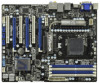
about the model you are using. www.asrock.com/support/index.asp 1.1 Package Contents ASRock 890GX Extreme4 Motherboard (ATX Form Factor: 12.0-in x 9.6-in, 30.5 cm x 24.4 cm) ASRock 890GX Extreme4 Quick Installation Guide ASRock 890GX Extreme4 Support CD 4 x Serial ATA (SATA) Data Cables (Optional - ASRock 890GX Extreme4 R2.0 | User Manual - Page 6
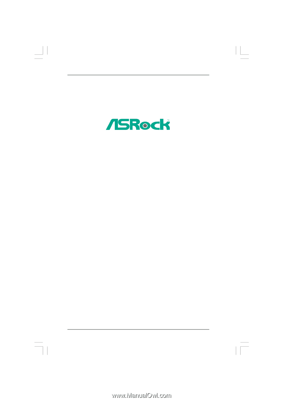
V8 + 2 Power Phase Design - Supports CPU up to 140W - Supports AMD's Cool 'n' QuietTM Technology - FSB 2600 MHz (5.2 GT/s) - Supports Untied Overclocking Technology (see CAUTION 2) - Supports Hyper-Transport 3.0 (HT 3.0) Technology - Northbridge: AMD 890GX - Southbridge: AMD SB850 - Dual Channel - ASRock 890GX Extreme4 R2.0 | User Manual - Page 7
7.1 CH HD Audio with Content Protection (Realtek ALC892 Audio Codec) - Premium Blu-ray audio support - Supports THX TruStudio ProTM - PCIE x1 Gigabit LAN 10/100/1000 Mb/s - Atheros® AR8151 - Supports Wake-On-LAN I/O Panel - 1 x PS/2 Keyboard Port - 1 x VGA/D-Sub Port - 1 x VGA/DVI-D Port - 1 x HDMI - ASRock 890GX Extreme4 R2.0 | User Manual - Page 8
CMOS Switch with LED - 1 x Power Switch with LED - 1 x Reset Switch with LED BIOS Feature - 32Mb AMI UEFI Legal BIOS with GUI support - Supports "Plug and Play" - ACPI 1.1 Compliance Wake Up Events - Supports jumperfree - SMBIOS 2.3.1 Support - CPU, VCCM, NB, SB Voltage Multi-adjustment - ASRock 890GX Extreme4 R2.0 | User Manual - Page 9
setting in the BIOS, applying Untied ASRock UCC (Unlock CPU Core) feature simplifies AMD CPU activation. As long as a simple switch of the UEFI option "ASRock motherboard, please refer to the memory support list on our website for the compatible memory modules. ASRock website http://www.asrock - ASRock 890GX Extreme4 R2.0 | User Manual - Page 10
or press key to BIOS setup menu to access ASRock Instant Flash. Just launch this tool and save the new BIOS file to your USB flash drive do is just to install the ASRock AIWI utility either from ASRock official website or ASRock software support CD to your motherboard, and also download the free - ASRock 890GX Extreme4 R2.0 | User Manual - Page 11
13. ASRock XFast USB can boost USB storage device performance. The performance may depend on the property of the device. 14. Although this motherboard offers stepless control, it is not recommended to perform over-clocking. Frequencies other than the recommended CPU bus frequencies may cause the - ASRock 890GX Extreme4 R2.0 | User Manual - Page 12
Motherboard (64 bit, 240-FpinSBmo8d0ul0e) 140W CPU FSB2.6GHz AM3+ Support 8-Core CPU DVI_CON1 VGA1 SOCKET AM3b HDMI1 Clr CMOS CHA_FAN1 890GX Extreme4 Super I/O PCIE3 Sideport memory 128MB PCI2 SATA3 6Gb/s CMOS BATTERY AMD SB850 Chipset AUDIO PCIE4 Front USB 3.0 CODEC PCI3 32Mb BIOS - ASRock 890GX Extreme4 R2.0 | User Manual - Page 13
1 . 4 I/O Panel 12 34 58 69 7 10 17 16 1 USB 2.0 Ports (USB45) 2 VGA/D-Sub Port 3 USB 2.0 Ports (USB23) * 4 LAN RJ-45 Port 5 Central / Bass (Orange) 6 Rear Speaker (Black) 7 Optical SPDIF Out Port 8 Line In (Light Blue) ** 9 Front Speaker (Lime) 15 14 13 12 11 10 11 12 *** 13 14 15 16 17 - ASRock 890GX Extreme4 R2.0 | User Manual - Page 14
Primary output" to use Rear Speaker, Central/Bass, and Front Speaker, or select "Realtek HDA Audio 2nd output" to use front panel audio. *** eSATA3 connector supports SATA Gen3 in cable 1M. 14 - ASRock 890GX Extreme4 R2.0 | User Manual - Page 15
the power is switched off or the power cord is detached from the power supply. Failure to do so may cause severe damage to the motherboard, peripherals, and/or components. 1. Unplug the power cord from the wall socket before touching any component. 2. To avoid damaging the - ASRock 890GX Extreme4 R2.0 | User Manual - Page 16
Socket Lever 2.2 Installation of CPU Fan and Heatsink After you install the CPU into this motherboard, it is necessary to install a larger heatsink and cooling fan to dissipate heat. No. 6). For proper installation, please kindly refer to the instruction manuals of the CPU fan and the heatsink. 16 - ASRock 890GX Extreme4 R2.0 | User Manual - Page 17
2.3 Installation of Memory Modules (DIMM) This motherboard provides four 240-pin DDR3 (Double Data Rate 3) DIMM slots, and supports Dual Channel Memory Technology. For dual channel configuration, you always need to install identical (the same brand, speed, size and chiptype) DDR3 DIMM pair in - ASRock 890GX Extreme4 R2.0 | User Manual - Page 18
matches the break on the slot. notch break notch break The DIMM only fits in one correct orientation. It will cause permanent damage to the motherboard and the DIMM if you force the DIMM into the slot at incorrect orientation. Step 3. Firmly insert the DIMM into the slot until the retaining - ASRock 890GX Extreme4 R2.0 | User Manual - Page 19
lane width graphics cards, or used to install PCI Express graphics cards to support CrossFireXTM function. PCIE4 (PCIE x16 slot; Blue) is used for PCI the installation. Step 2. Remove the system unit cover (if your motherboard is already installed in a chassis). Step 3. Remove the bracket facing - ASRock 890GX Extreme4 R2.0 | User Manual - Page 20
easily enjoy the benefits of dual monitor feature without installing any add-on VGA card to this motherboard. This motherboard also provides independent display controllers for DVI-D, D-Sub and HDMI to support dual VGA output so that DVI-D, D-sub and HDMI can drive same or different display contents - ASRock 890GX Extreme4 R2.0 | User Manual - Page 21
Surround Display Feature This motherboard supports surround display upgrade. With the internal VGA output support (DVI-D, D-Sub not adjust the UEFI setup, the default value of "Share Memory", [Auto], will disable VGA/D-Sub function when the add-on VGA card is inserted to this motherboard. 4. Install - ASRock 890GX Extreme4 R2.0 | User Manual - Page 22
function is supported on this motherboard. To use HDCP function with this motherboard, you need to adopt the monitor that supports HDCP function as well. Therefore, you can enjoy the superior display quality with high-definition HDCP encryption contents. Please refer to below instruction for more - ASRock 890GX Extreme4 R2.0 | User Manual - Page 23
Operation Guide This motherboard supports CrossFireXTM supported with Windows® XP with Service Pack 2 / VistaTM / 7 OS. 3-way CrossFireXTM and Quad CrossFireXTM feature are supported , please refer to ATITM graphics card manuals for detailed installation guide. Step 1. Insert one Radeon graphics - ASRock 890GX Extreme4 R2.0 | User Manual - Page 24
Bridge Interconnects on the top of Radeon graphics cards. (CrossFire Bridge is provided with the graphics card you purchase, not bundled with this motherboard. Please refer to your graphics card vendor for details.) CrossFire Bridge or Step 3. Connect the DVI monitor cable to the DVI connector - ASRock 890GX Extreme4 R2.0 | User Manual - Page 25
Bridge to connect Radeon graphics cards on PCIE3 and PCIE4 slots. (CrossFireTM Bridge is provided with the graphics card you purchase, not bundled with this motherboard. Please refer to your graphics card vendor for details.) 25 - ASRock 890GX Extreme4 R2.0 | User Manual - Page 26
CrossFireTM Bridge Step 5. Connect the DVI monitor cable to the DVI connector on the Radeon graphics card on PCIE2 slot. (You may use the DVI to D-Sub adapter to convert the DVI connector to D-Sub interface, and then connect the D-Sub monitor cable to the DVI to D-Sub adapter.) 26 - ASRock 890GX Extreme4 R2.0 | User Manual - Page 27
Step 3. Step 4. Step 5. Install the required drivers to your system. For Windows® XP OS: A. ATITM recommends Windows® XP Service Pack 2 or higher to be installed (If you have Windows® XP Service Pack 2 or higher installed in your system, there is no need to download it again): http://www.microsoft - ASRock 890GX Extreme4 R2.0 | User Manual - Page 28
Although you have selected the option "Enable CrossFireTM", the CrossFireXTM function may not work actually. Your computer will automatically reboot. After restarting your computer, please confirm whether the option "Enable CrossFireTM" in "ATI Catalyst Control Center" is selected or not; if not, - ASRock 890GX Extreme4 R2.0 | User Manual - Page 29
Guide This motherboard supports ATITM Hybrid CrossFireXTM feature. ATITM Hybrid CrossFireXTM brings multi-GPU performance capabilities by enabling an AMD 890GX on PCIE2 slot. Step 3. Boot your system. Press to enter BIOS setup. Enter "Advanced" screen, and enter "Chipset Settings". Then set the - ASRock 890GX Extreme4 R2.0 | User Manual - Page 30
Step 7. Double-click "ATI Catalyst Control Center". Click "View", click "CrossFireTM", and then select the option "Enable CrossFireTM". View CrossFireTM Enable CrossFireTM Step 8. Click "Yes" to continue. Step 9. Click "OK" to save your change. Step 10. Reboot your system. Then you can freely - ASRock 890GX Extreme4 R2.0 | User Manual - Page 31
and pin3 on CLRCMOS1 for 5 seconds. However, please do not clear the CMOS right after you update the BIOS. If you need to clear the CMOS when you just finish updating the BIOS, you must boot up the system first, and then shut it down before you do the clear-CMOS action - ASRock 890GX Extreme4 R2.0 | User Manual - Page 32
SATA data cable can be connected to the SATA3 hard disk or the SATA3 connector on this motherboard. Please connect the black end of SATA power cable to the power connector on each drive I/O panel, there are three USB 2.0 headers on this motherboard. Each USB 2.0 header can support two USB 2.0 ports. - ASRock 890GX Extreme4 R2.0 | User Manual - Page 33
panel, there is one USB 3.0 header on this motherboard. This USB 3.0 header can support two USB 3.0 ports. Infrared Module Header (5-pin IR1 supports Jack Sensing, but the panel wire on the chassis must support HDA to function correctly. Please follow the instruction in our manual and chassis manual - ASRock 890GX Extreme4 R2.0 | User Manual - Page 34
Connect the power switch, reset switch and system status indicator on the chassis to this header according to the pin assignments below. Note the positive and negative pins before connecting the cables. PWRBTN (Power Switch): Connect to the power switch on the chassis front panel. You may configure - ASRock 890GX Extreme4 R2.0 | User Manual - Page 35
the black wire to the ground pin. CHA_FAN1/2/3 fan speed can be controlled through UEFI or AXTU. (3-pin CHA_FAN3) (see p.12 No. 43) (3-pin PWR_FAN1) ( the black wire to the ground pin. Though this motherboard provides 4-Pin CPU fan (Quiet Fan) support, the 3-Pin CPU fan still can work successfully - ASRock 890GX Extreme4 R2.0 | User Manual - Page 36
default IEEE 1394 port on the I/O panel, there is one IEEE 1394 header (FRONT_1394) on this motherboard. This IEEE 1394 header can support one IEEE 1394 port. This COM1 header supports a serial port module. HDMI_SPDIF Header (2-pin HDMI_SPDIF1) (see p.12 No. 33) 1 GND SPDIFOUT HDMI_SPDIF header - ASRock 890GX Extreme4 R2.0 | User Manual - Page 37
5 Plug the Front USB 3.0 cable into the USB 3.0 Step 6 The Front USB 3.0 Panel is ready header (USB3_2_3) on the motherboard. to use. Rear USB 3.0 Bracket Installation Guide Step 1 Unscrew the two screws from the Front USB 3.0 Panel. Step 2 Put the USB 3.0 cable and the rear USB 3.0 bracket - ASRock 890GX Extreme4 R2.0 | User Manual - Page 38
2.10 Smart Switches This motherboard has three smart switches: power switch, reset switch and clear CMOS switch, allowing users to quickly turn on/off or reset the system or clear - ASRock 890GX Extreme4 R2.0 | User Manual - Page 39
2.11 Dr. Debug Dr. Debug is used to provide code information, which makes troubleshooting even easier. Please see the diagrams below for reading the Dr. Debug codes. Status Code 0x00 0x01 0x02 0x03 0x04 0x05 0x06 0x07 0x08 0x09 - ASRock 890GX Extreme4 R2.0 | User Manual - Page 40
0x37 0x38 0x39 0x3A 0x3B 0x3C 0x3D 0x3E 0x3F-0x4E 0x4F 0x50 0x51 0x52 0x53 0x54 0x55 0x56 0x57 0x58 0x59 0x5A 0x5B 0x5C-0x5F 0xE0 0xE1 0xE2 0xE3 0xE4-0xE7 0xE8 0xE9 0xEA 0xEB 0xEC-0xEF 0xF0 0xF1 0xF2 0xF3 0xF4 0xF5-0xF7 0xF8 0xF9 0xFA 0xFB - 0xFF 0x60 0X61 Post-Memory North Bridge initialization is - ASRock 890GX Extreme4 R2.0 | User Manual - Page 41
0x95 0x96 0x97 0x98 0x99 0x9A 0x9B 0x9C 0x9D 0x9E - 0x9F 0xA0 0xA1 0xA2 0xA3 0xA4 0xA5 Installation of the South Bridge Runtime Services CPU DXE initialization is started CPU DXE initialization (CPU module specific) CPU DXE initialization (CPU module specific) CPU DXE initialization (CPU module - ASRock 890GX Extreme4 R2.0 | User Manual - Page 42
Codes section below) Setup Input Wait Reserved for ASL (see ASL Status Codes section below) Ready To Boot event Legacy Boot event Exit Boot Services event Runtime Set Virtual Address MAP Begin Runtime Set Virtual Address MAP End Legacy Option ROM Initialization System Reset USB hot plug PCI bus hot - ASRock 890GX Extreme4 R2.0 | User Manual - Page 43
Serial ATA3 (SATA3) Hard Disks Installation This motherboard adopts AMD SB850 chipset that supports Serial ATA3 (SATA3) hard disks and RAID functions. You may install SATA3 hard disks on this motherboard for internal storage devices. This section will guide you to install the SATA3 hard disks. STEP - ASRock 890GX Extreme4 R2.0 | User Manual - Page 44
is installed into system properly. The latest SATA3 driver is available on our support website: www.asrock.com 4. Make sure to use the SATA power cable & data cable, which are from our motherboard package. 5. Please follow below instructions step by step to reduce the risk of HDD crash or data loss - ASRock 890GX Extreme4 R2.0 | User Manual - Page 45
cable to (White) to the power supply 1x4-pin cable. the motherboard's SATA3 connector. SATA power cable 1x4-pin power connector (White) Step attention, before you process the Hot Unplug: Please do follow below instruction sequence to process the Hot Unplug, improper procedure will cause the SATA3 - ASRock 890GX Extreme4 R2.0 | User Manual - Page 46
follow below steps. STEP 1: Set up UEFI. A. Enter UEFI SETUP UTILITY Advanced screen Storage Configuration. B. Set the "SATA Mode" option to [RAID]. STEP 2: Make a SATA3 Driver Diskette. (Please use USB floppy or floppy disk.) A. Insert the ASRock Support CD into your optical drive to boot - ASRock 890GX Extreme4 R2.0 | User Manual - Page 47
configure RAID function, you need to check the RAID installation guide in the Support CD for proper configuration. Please refer to the BIOS RAID installation guide part of the document in the following path in the Support CD: .. \ RAID Installation Guide STEP 4: Install Windows® XP / XP 64-bit OS on - ASRock 890GX Extreme4 R2.0 | User Manual - Page 48
the driver to install according to the OS you install. Using SATA3 HDDs without NCQ and Hot Plug functions (IDE mode) STEP 1: Set up UEFI. A. Enter UEFI SETUP UTILITY Advanced screen Storage Configuration. B. Set the "SATA Mode" option to [IDE]. STEP 2: Install Windows® XP / XP 64-bit OS on - ASRock 890GX Extreme4 R2.0 | User Manual - Page 49
Technology This motherboard supports Untied Overclocking Technology, which means during overclocking, FSB enjoys better margin due to fixed PCI / PCIE buses. Before you enable Untied Overclocking function, please enter "Overclock Mode" option of UEFI setup to set the selection from [Auto] to [Manual - ASRock 890GX Extreme4 R2.0 | User Manual - Page 50
SETUP UTILITY 3.1 Introduction This section explains how to use the UEFI SETUP UTILITY to configure your system. The SPI Memory on the motherboard stores the UEFI SETUP UTILITY. You may run the UEFI SETUP UTILITY when you start up the computer. Please press or during the Power-On-Self - ASRock 890GX Extreme4 R2.0 | User Manual - Page 51
for all the settings To save changes and exit the UEFI SETUP UTILITY To jump to the Exit Screen or exit the current screen 3.2 Main Screen When you enter the UEFI SETUP UTILITY, the Main screen will appear and display the system overview. System - ASRock 890GX Extreme4 R2.0 | User Manual - Page 52
stability. ASRock UCC ASRock UCC (Unlock CPU Core) feature simplifies AMD CPU activation. As long as a simple switch of the UEFI option "ASRock UCC", better price. Please be noted that UCC feature is supported with AM3/AM3+ CPU only, and in addition, not every AM3/AM3+ CPU can support this function - ASRock 890GX Extreme4 R2.0 | User Manual - Page 53
set to [Auto] by default. If it is set to [Manual], you may adjust the value of Processor Frequency and Processor Voltage. 16 Bit]. DRAM Configuration DRAM Frequency If [Auto] is selected, the motherboard will detect the memory module(s) inserted and assigns appropriate frequency automatically. DRAM - ASRock 890GX Extreme4 R2.0 | User Manual - Page 54
], [Address bits 6], [Address bits 12], [HASH 1] and [HASH 2]. The default value is [HASH 2]. CAS# Latency (tCL) Use this item to change CAS# Latency (tCL) Auto/Manual setting. The default is [Auto]. RAS# to CAS# Delay (tRCD) Use this item to change RAS# to CAS# Delay (tRCD) Auto - ASRock 890GX Extreme4 R2.0 | User Manual - Page 55
Four Activate Window (tFAW) Use this item to change Four Activate Window (tFAW) Auto/Manual setting. The default is [Auto]. GPU Clock Override Onboard GPU Clock Override Use this item to enable ot disable GPU clock override. The default value - ASRock 890GX Extreme4 R2.0 | User Manual - Page 56
Setting wrong values in this section may cause the system to malfunction. ASRock Instant Flash ASRock Instant Flash is a UEFI flash utility embedded in Flash ROM. This convenient UEFI update tool allows you to update system UEFI without entering operating systems first like MS-DOS or Windows®. Just - ASRock 890GX Extreme4 R2.0 | User Manual - Page 57
]. Configuration options: [Enabled] and [Disabled]. Enhance Halt State (C1E) All processors support the Halt State (C1). The C1 state is supported through the native processor instructions HLT and MWAIT and requires no hardware support from the chipset. In the C1 power state, the processor maintains - ASRock 890GX Extreme4 R2.0 | User Manual - Page 58
you set "Internal Graphics Mode" to [UMA]. Onboard HDMI HD Audio This allows you to enable or disable the onboard HDMI HD Audio in AMD 890GX. If you use Dual-link DVI monitor, please set this item to [Disabled]. Primary Graphics Adapter This item will switch the PCI Bus scanning order - ASRock 890GX Extreme4 R2.0 | User Manual - Page 59
3.4.3 South Bridge Configuration Onboard HD Audio Select [Auto], [Enabled] or [Disabled] for the onboard HD Audio feature. If you select [Auto], the onboard HD Audio will be disabled when PCI Sound Card is plugged. Front Panel Select [Auto] or [Disabled] for the onboard HD Audio Front Panel. Onboard - ASRock 890GX Extreme4 R2.0 | User Manual - Page 60
3.4.4 Storage Configuration SATA Controller Use this item to enable or disable the "SATA Controller" feature. SATA Mode Use this item to adjust SATA Mode. The default value of this option is [IDE Mode]. Configuration options: [AHCI Mode], [RAID Mode] and [IDE Mode]. If you set this item to RAID mode - ASRock 890GX Extreme4 R2.0 | User Manual - Page 61
3.4.5 Super IO Configuration Serial Port Use this item to enable or disable the onboard serial port. Serial Port Address Use this item to set the address for the onboard serial port. Configuration options: [Auto], [3F8 / IRQ4], [2F8 / IRQ3], [3E8 / IRQ4], [2E8 / IRQ3]. Infrared Port Use this item to - ASRock 890GX Extreme4 R2.0 | User Manual - Page 62
-detect or disable the Suspend-toRAM feature. Select [Auto] will enable this feature if the OS supports it. Check Ready Bit Use this item to enable or disable the feature Check Ready Bit. Restore this option to [Enabled] if you plan to use this motherboard to submit Windows® VistaTM certification. 62 - ASRock 890GX Extreme4 R2.0 | User Manual - Page 63
this item to enable or disable the use of USB 3.0 controller. Legacy USB Support Use this option to select legacy support for USB devices. There are four confi guration options: [Enabled], [Auto], [Disabled] and [UEFI Setup Only]. The default value is [Enabled]. Please refer to below descriptions - ASRock 890GX Extreme4 R2.0 | User Manual - Page 64
hardware on your system, including the parameters of the CPU temperature, motherboard temperature, CPU fan speed, chassis fan speed, and the critical voltage set the chassis fan 1 speed. Confi guration options: [Full On], [Manual Mode] and [Automatic Mode]. The default is value [Full On]. Chassis - ASRock 890GX Extreme4 R2.0 | User Manual - Page 65
3.6 Boot Screen In this section, it will display the available devices on your system for you to configure the boot settings and the boot priority. Setup Prompt Timeout This shows the number of seconds to wait for setup activation key. 65535(0XFFFF) means indefi nite waiting. Bootup Num-Lock If this - ASRock 890GX Extreme4 R2.0 | User Manual - Page 66
3.7 Security Screen In this section, you may set or change the supervisor/user password for the system. For the user password, you may also clear it. 66 - ASRock 890GX Extreme4 R2.0 | User Manual - Page 67
and exit setup?" Select [OK] to save the changes and exit the UEFI SETUP UTILITY. Discard Changes and Exit When you select this option, it message, "Discard changes and exit setup?" Select [OK] to exit the UEFI SETUP UTILITY without saving any changes. Discard Changes When you select this option - ASRock 890GX Extreme4 R2.0 | User Manual - Page 68
applications software that the motherboard supports. Click on a specific item then follow the installation wizard to install it. 4.2.4 Contact Information If you need to contact ASRock or want to know more about ASRock, welcome to visit ASRock's website at http://www.asrock - ASRock 890GX Extreme4 R2.0 | User Manual - Page 69
Installing OS on a HDD Larger Than 2TB This motherboard is adopting UEFI BIOS that allows Windows® OS to be installed on a large size HDD (>2TB). Please follow below procedure to install the operating system. 1. Please make sure to
-
 1
1 -
 2
2 -
 3
3 -
 4
4 -
 5
5 -
 6
6 -
 7
7 -
8
-
9
-
10
-
11
-
12
-
13
-
14
-
15
-
16
-
17
-
18
-
19
-
20
-
21
-
22
-
23
-
24
-
25
-
26
-
27
-
28
-
29
-
30
-
31
-
32
-
33
-
34
-
35
-
36
-
37
-
38
-
39
-
40
-
41
-
42
-
43
-
44
-
45
-
46
-
47
-
48
-
49
-
50
-
51
-
52
-
53
-
54
-
55
-
56
-
57
-
58
-
59
-
60
-
61
-
62
-
63
-
64
-
65
-
66
-
67
-
68
-
69
 |
 |
1
890GX Extreme4
User Manual
Version 2.0
Published February 2011
Copyright©2011 ASRock INC. All rights reserved.