ASRock 890GX Pro3 User Manual
ASRock 890GX Pro3 Manual
 |
View all ASRock 890GX Pro3 manuals
Add to My Manuals
Save this manual to your list of manuals |
ASRock 890GX Pro3 manual content summary:
- ASRock 890GX Pro3 | User Manual - Page 1
890GX Pro3 User Manual Version 1.0 Published January 2011 Copyright©2011 ASRock INC. All rights reserved. 1 - ASRock 890GX Pro3 | User Manual - Page 2
any form or by any means, except duplication of documentation by the purchaser for backup purpose, without written consent of ASRock Inc. Products and corporate names appearing in this manual may or may not be registered trademarks or copyrights of their respective companies, and are used only for - ASRock 890GX Pro3 | User Manual - Page 3
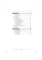
2.10 Smart Switches 35 2.11 Dr. Debug 36 2.12 Serial ATA3 (SATA3) Hard Disks Installation 40 2.13 Hot Plug and Hot Swap Functions for SATA3 HDDs 40 2.14 SATA3 HDD Hot Plug Feature and Operation Guide 41 2.15 Driver Installation Guide 43 2.16 Installing Windows® 7 / 7 64-bit / VistaTM / VistaTM - ASRock 890GX Pro3 | User Manual - Page 4
UEFI Menu Bar 47 3.1.2 Navigation Keys 48 3.2 Main Screen 48 3.3 OC Tweaker Screen 49 3.4 Advanced Screen 53 3.4.1 CPU Configuration 64 4 . Software Support 65 4.1 Install Operating System 65 4.2 Support CD Information 65 4.2.1 Running Support CD 65 4.2.2 Drivers Menu 65 4.2.3 Utilities - ASRock 890GX Pro3 | User Manual - Page 5
Contents ASRock 890GX Pro3 Motherboard (ATX Form Factor: 12.0-in x 9.6-in, 30.5 cm x 24.4 cm) ASRock 890GX Pro3 Quick Installation Guide ASRock 890GX Pro3 Support CD 2 x Serial ATA (SATA) Data Cables (Optional) 1 x I/O Panel Shield ASRock Reminds You... To get better performance in Windows® 7 / 7 64 - ASRock 890GX Pro3 | User Manual - Page 6
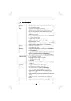
1.2 Specifications Platform CPU Chipset Memory Expansion Slot Graphics - ATX Form Factor: 12.0-in x 9.6-in, 30.5 cm x 24.4 cm - All Solid Capacitor design - Support for Socket AM3+ processors - Support for Socket AM3 processors: AMD PhenomTM II X6 / X4 / X3 / X2 (except 920 / 940) / Athlon II X4 / - ASRock 890GX Pro3 | User Manual - Page 7
1394 header - 1 x HDMI_SPDIF header - 1 x Power LED header - CPU/Chassis/Power FAN connector - 24 pin ATX power connector - 8 pin 12V power connector - Front panel audio connector - 3 x USB 2.0 headers (support 6 USB 2.0 ports) - 1 x Dr. Debug (7-Segment Debug LED) - 1 x Clear CMOS Switch with LED - ASRock 890GX Pro3 | User Manual - Page 8
- 32Mb AMI UEFI Legal BIOS with GUI support - Supports "Plug and Play" - ACPI 1.1 Compliance Wake Up Events - Supports jumperfree - SMBIOS 2.3.1 Support - CPU, VCCM, NB, SB Voltage Multi-adjustment Support CD - Drivers, Utilities, AntiVirus Software (Trial Version), AMD OverDriveTM Utility - ASRock 890GX Pro3 | User Manual - Page 9
XP. For Windows® OS with 64-bit CPU, there is no such limitation. 6. The maximum shared memory size is defined by the chipset vendor and is subject to change. Please check AMD website for the latest information. 7. For microphone input, this motherboard supports both stereo and mono modes. For audio - ASRock 890GX Pro3 | User Manual - Page 10
charging when your PC enters into Standby mode (S1), Suspend to RAM (S3), hibernation mode (S4) or power off (S5). With APP Charger driver installed, you can easily enjoy the marvelous charging experience than ever. ASRock website: http://www.asrock.com/Feature/AppCharger/index.asp 12. SmartView - ASRock 890GX Pro3 | User Manual - Page 11
CPU. 15. While CPU overheat is detected, the system will automatically shutdown. Before you resume the system, please check if the CPU fan on the motherboard system shall be under 1.00W in off mode condition. To meet EuP standard, an EuP ready motherboard and an EuP ready power supply are required - ASRock 890GX Pro3 | User Manual - Page 12
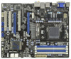
3.0 Hybrid CrossFire CMOS BATTERY 890GX Pro3 CHA_FAN3 Designed in Taipei Super I/O PCI1 PCIE3 ErP/EuP Ready AUDIO CODEC PCI2 RoHS PCI3 HD_AUDIO1 IR1 HDMI_SPDIF1 1 1 1 COM1 1 USB6_7 1 USB8_9 1 SATAIII_3_4 SATAIII_1_2 SATA3 6Gb/s AMD SB850 Chipset 1394a 32Mb BIOS CLRCMOS1 1 Dr - ASRock 890GX Pro3 | User Manual - Page 13
1.4 I/O Panel 12 34 58 69 7 10 17 16 1 USB 2.0 Ports (USB45) 2 VGA/D-Sub Port 3 USB 2.0 Ports (USB23) * 4 LAN RJ-45 Port 5 Central / Bass (Orange) 6 Rear Speaker (Black) 7 Optical SPDIF Out Port 8 Line In (Light Blue) ** 9 Front Speaker (Lime) 15 14 13 12 11 10 11 12 *** 13 14 15 16 17 - ASRock 890GX Pro3 | User Manual - Page 14
Primary output" to use Rear Speaker, Central/Bass, and Front Speaker, or select "Realtek HDA Audio 2nd output" to use front panel audio. *** eSATA3 connector supports SATA Gen3 in cable 1M. 14 - ASRock 890GX Pro3 | User Manual - Page 15
, peripherals, and/or components. 1. Unplug the power cord from the wall socket before touching any component. 2. To avoid damaging the motherboard components due to static electricity, NEVER place your motherboard directly on the carpet or the like. Also remember to use a grounded wrist strap - ASRock 890GX Pro3 | User Manual - Page 16
Socker Corner Small Triangle STEP 2 / STEP 3: Match The CPU Golden Triangle To The Socket Corner Small Triangle STEP 4: Push Down And Lock The Socket Lever 2.2 Installation of CPU Fan and Heatsink After you install the CPU into this motherboard, it is necessary to install a larger heatsink and - ASRock 890GX Pro3 | User Manual - Page 17
2.3 Installation of Memory Modules (DIMM) This motherboard provides four 240-pin DDR3 (Double Data Rate 3) DIMM slots, and supports Dual Channel Memory Technology. For dual channel configuration, you always need to install identical (the same brand, speed, size and chiptype) DDR3 DIMM pair in the - ASRock 890GX Pro3 | User Manual - Page 18
matches the break on the slot. notch break notch break The DIMM only fits in one correct orientation. It will cause permanent damage to the motherboard and the DIMM if you force the DIMM into the slot at incorrect orientation. Step 3. Firmly insert the DIMM into the slot until the retaining - ASRock 890GX Pro3 | User Manual - Page 19
or used to install PCI Express graphics cards to support CrossFireXTM function. 1. In single VGA card mode, it is recommended to install a PCI Express the installation. Step 2. Remove the system unit cover (if your motherboard is already installed in a chassis). Step 3. Remove the bracket facing - ASRock 890GX Pro3 | User Manual - Page 20
yet, please install onboard VGA driver from our support CD to your system and restart your computer. Then you can start to use dual monitor function on this motherboard. 1. DVI-D and HDMI ports cannot function at the same time. When one of them is enabled, the other one will be disabled. 2. When - ASRock 890GX Pro3 | User Manual - Page 21
memory. If you do not adjust the UEFI setup, the default value of "Share Memory", [Auto], will disable VGA/D-Sub function when the add-on VGA card is inserted to this motherboard. 4. Install the onboard VGA driver the number 2. D. Click "Extend my Windows desktop onto this monitor". E. Right-click - ASRock 890GX Pro3 | User Manual - Page 22
For Windows® 7 / 7 64- supported on this motherboard. To use HDCP function with this motherboard, you need to adopt the monitor that supports HDCP function as well. Therefore, you can enjoy the superior display quality with high-definition HDCP encryption contents. Please refer to below instruction - ASRock 890GX Pro3 | User Manual - Page 23
, 3450 or 5450 series graphics processor and a motherboard based on an AMD 890GX integrated chipset, all operating in a Windows® VistaTM / 7 environment. Please refer to below PCI Express graphics card support list for ATITM Hybrid CrossFireXTM. Vendor Chipset ATI RADEON HD2400XT RADEON HD3450 - ASRock 890GX Pro3 | User Manual - Page 24
system. Then you can freely enjoy the benefit of HybridTM CrossFireXTM feature. * Hybrid CrossFireXTM appearing here is a registered trademark of ATITM Technologies Inc., and is For further information of ATITM Hybrid CrossFireXTM technology, please check AMD website for up dates and details. 24 - ASRock 890GX Pro3 | User Manual - Page 25
supported with Windows® XP with Service Pack 2 / VistaTM / 7 OS. Quad CrossFireXTM feature are supported with Windows® VistaTM / 7 OS only. Please check AMD website for ATITM CrossFireXTM driver updates refer to ATITM graphics card manuals for detailed installation guide. Step 1. Insert one Radeon - ASRock 890GX Pro3 | User Manual - Page 26
Bridge is provided with the graphics card you purchase, not bundled with this motherboard. Please refer to your graphics card vendor for details.) CrossFire Bridge or Step 3. Connect the DVI monitor cable to the DVI connector on the Radeon graphics card on PCIE2 slot. (You may use the DVI - ASRock 890GX Pro3 | User Manual - Page 27
for ATITM driver updates. Step 3. Step 4. Step 5. Install the required drivers to your system. For Windows® XP OS: A. ATITM recommends Windows® XP Service Pack 2 or higher to be installed (If you have Windows® XP Service Pack 2 or higher installed in your system, there is no need to download it - ASRock 890GX Pro3 | User Manual - Page 28
is used only for identification or explanation and to the owners' benefit, without intent to infringe. * For further information of ATITM CrossFireXTM technology, please check AMD website for updates and details. 28 - ASRock 890GX Pro3 | User Manual - Page 29
short pin2 and pin3 on CLRCMOS1 for 5 seconds. However, please do not clear the CMOS right after you update the BIOS. If you need to clear the CMOS when you just finish updating the BIOS, you must boot up the system first, and then shut it down before you do the clear-CMOS action - ASRock 890GX Pro3 | User Manual - Page 30
hard disk or the SATA3 connector on this motherboard. Besides four default USB 2.0 ports on the I/O panel, there are three USB 2.0 headers on this motherboard. Each USB 2.0 header can support two USB 2.0 ports. This header supports an optional wireless transmitting and receiving infrared module - ASRock 890GX Pro3 | User Manual - Page 31
supports Jack Sensing, but the panel wire on the chassis must support HDA to function correctly. Please follow the instruction in our manual and chassis manual activate the front mic. For Windows® XP / XP 64-bit OS: Select "Mixer". Select "Recorder". Then click "FrontMic". For Windows® 7 / 7 64-bit - ASRock 890GX Pro3 | User Manual - Page 32
. Please connect the fan cables to the fan connectors and match the black wire to the ground pin. CHA_FAN1/2/3 fan speed can be controlled through UEFI or AXTU utility. (3-pin CHA_FAN3) (see p.12 No. 12) (3-pin PWR_FAN1) (see p.12 No. 2) GND +12V CHA_FAN_SPEED PWR_FAN_SPEED +12V GND - ASRock 890GX Pro3 | User Manual - Page 33
) support, the 3-Pin CPU fan still can work successfully even without the fan speed control function. If you plan to connect the 3-Pin CPU fan to the CPU fan connector on this motherboard, please connect it to Pin 1-3. Pin 1-3 Connected 3-Pin Fan Installation (3-pin CPU_FAN2) (see p.12 No. 5) ATX - ASRock 890GX Pro3 | User Manual - Page 34
No.31) HDMI_SPDIF Header (2-pin HDMI_SPDIF1) (see p.12 No. 33) RRXD1 DDTR#1 DDSR#1 CCTS#1 1 RRI#1 RRTS#1 GND TTXD1 DDCD#1 1 GND SPDIFOUT This COM1 header supports a serial port module. HDMI_SPDIF header, providing SPDIF audio output to HDMI VGA card, allows the system to con nect HDMI Digital TV - ASRock 890GX Pro3 | User Manual - Page 35
2.10 Smart Switches This motherboard has three smart switches: power switch, reset switch and clear CMOS switch, allowing users to quickly turn on/off or reset the system or clear - ASRock 890GX Pro3 | User Manual - Page 36
2.11 Dr. Debug Dr. Debug is used to provide code information, which makes troubleshooting even easier. Please see the diagrams below for reading the Dr. Debug codes. Status Code 0x00 0x01 0x02 0x03 0x04 0x05 0x06 0x07 0x08 0x09 0x0A 0x0B 0x0C - 0x0D 0x0E 0x0F 0x10 0x11 0x12 0x13 0x14 0x15 - ASRock 890GX Pro3 | User Manual - Page 37
do not match Memory initialization error. No usable memory detected Unspecified memory initialization error Memory not installed Invalid CPU type or Speed CPU mismatch CPU self test failed or possible CPU cache error CPU micro-code is not found or micro-code update is failed Internal CPU error reset - ASRock 890GX Pro3 | User Manual - Page 38
Services CPU DXE initialization is started CPU DXE initialization (CPU module specific) CPU DXE initialization (CPU module specific) CPU DXE initialization (CPU module specific) CPU DXE initialization (CPU Device Selection (BDS) phase is started Driver connecting is started PCI Bus initialization is - ASRock 890GX Pro3 | User Manual - Page 39
section below) Ready To Boot event Legacy Boot event Exit Boot Services event Runtime Set Virtual Address MAP Begin Runtime Set Virtual Address future AMI codes OEM BDS initialization codes CPU initialization error North Bridge initialization error update is failed Reset protocol is not available 39 - ASRock 890GX Pro3 | User Manual - Page 40
hard disk. 2.13 Hot Plug and Hot Swap Functions for SATA3 HDDs This motherboard supports Hot Plug and Hot Swap functions for SATA3 in RAID / AHCI mode. AMD SB850 chipset provides hardware support for Advanced Host controller Interface (AHCI), a new programming interface for SATA host controllers - ASRock 890GX Pro3 | User Manual - Page 41
is installed into system properly. The latest SATA3 driver is available on our support website: www.asrock.com 4. Make sure to use the SATA power cable & data cable, which are from our motherboard package. 5. Please follow below instructions step by step to reduce the risk of HDD crash or data - ASRock 890GX Pro3 | User Manual - Page 42
cable to (White) to the power supply 1x4-pin cable. the motherboard's SATA3 connector. SATA power cable 1x4-pin power connector (White) Step attention, before you process the Hot Unplug: Please do follow below instruction sequence to process the Hot Unplug, improper procedure will cause the SATA3 - ASRock 890GX Pro3 | User Manual - Page 43
follow below steps. STEP 1: Set up UEFI. A. Enter UEFI SETUP UTILITY Advanced screen Storage Configuration. B. Set the "SATA Mode" option to [RAID]. STEP 2: Make a SATA3 Driver Diskette. (Please use USB floppy or floppy disk.) A. Insert the ASRock Support CD into your optical drive to boot - ASRock 890GX Pro3 | User Manual - Page 44
refer to the BIOS RAID installation guide part of the document in the following path in the Support CD: .. \ RAID Installation Guide STEP 3: Make a SATA3 Driver Diskette. Make a SATA3 driver diskette by following section 2.16.1 step 2 on page 43. STEP 4: Install Windows® 7 / 7 64-bit / VistaTM - ASRock 890GX Pro3 | User Manual - Page 45
(AHCI mode) STEP 1: Set up UEFI. A. Enter UEFI SETUP UTILITY Advanced screen Storage Configuration. B. Set the "SATA Mode" option to [AHCI]. STEP 2: Make a SATA3 driver diskette. Make a SATA3 driver diskette by following section 2.16.1 step 2 on page 43. STEP 3: Install Windows® XP - ASRock 890GX Pro3 | User Manual - Page 46
(IDE mode) STEP 1: Set up UEFI. A. Enter UEFI SETUP UTILITY Advanced screen Storage Configuration. B. Set the "SATA Mode" option to [IDE]. STEP 2: Install Windows® 7 / 7 64-bit / VistaTM / VistaTM 64-bit OS on your system. 2.18 Untied Overclocking Technology This motherboard supports Untied - ASRock 890GX Pro3 | User Manual - Page 47
UEFI SETUP UTILITY to configure your system. The SPI Memory on the motherboard stores the UEFI SETUP UTILITY. You may run the UEFI Because the UEFI software is constantly being updated, the following UEFI setup screens set up overclocking features Advanced To set up the advanced UEFI features H/W - ASRock 890GX Pro3 | User Manual - Page 48
for all the settings To save changes and exit the UEFI SETUP UTILITY To jump to the Exit Screen or exit the current screen 3.2 Main Screen When you enter the UEFI SETUP UTILITY, the Main screen will appear and display the system overview. System - ASRock 890GX Pro3 | User Manual - Page 49
Overclock Mode. Configuration options: [Auto] and [Manual]. The default value is [Auto]. Spread Spectrum This item should always be [Auto] for better system stability. ASRock UCC ASRock UCC (Unlock CPU Core) feature simplifies AMD CPU activation. As long as a simple switch of the UEFI option "ASRock - ASRock 890GX Pro3 | User Manual - Page 50
for system stability. CPU Frequency (MHz) Use this option to adjust CPU frequency. CPU Voltage It allows you to adjust the value of CPU voltage. However, DRAM Frequency If [Auto] is selected, the motherboard will detect the memory module(s) inserted and assigns appropriate frequency automatically. - ASRock 890GX Pro3 | User Manual - Page 51
or disable DDR power down mode. Bank Interleaving Interleaving allows memory accesses to be spread out over banks on the same node, or accross nodes, decreasing access contention. Channel Interleaving It allows you to enable Channel Memory Interleaving. Configuration options: [Disabled], [Address - ASRock 890GX Pro3 | User Manual - Page 52
) Use this item to change Four Activate Window (tFAW) Auto/Manual setting. The default is [Auto]. GPU Clock is [Auto]. CPU Load-Line Calibration CPU Load-Line Calibration helps prevent CPU voltage droop when the system is under heavy load. CPU VDDA Voltage Use this to select CPU VDDA Voltage. The - ASRock 890GX Pro3 | User Manual - Page 53
section may cause the system to malfunction. ASRock Instant Flash ASRock Instant Flash is a UEFI flash utility embedded in Flash ROM. This convenient UEFI update tool allows you to update system UEFI without entering operating systems first like MS-DOS or Windows®. Just launch this tool and save the - ASRock 890GX Pro3 | User Manual - Page 54
). The C1 state is supported through the native processor instructions HLT and MWAIT and requires no hardware support from the chipset. In the C1 power state, the processor maintains the context of the system caches. CPU Thermal Throttle Use this item to enable CPU internal thermal control mechanism - ASRock 890GX Pro3 | User Manual - Page 55
Graphics Mode" to [UMA]. Onboard HDMI HD Audio This allows you to enable or disable the onboard HDMI HD Audio in AMD 890GX. If you use Dual-link DVI monitor, please set this item to [Disabled]. Surround View This allows you to enable or disable the Surround View feature or Hybrid CrossFireXTM - ASRock 890GX Pro3 | User Manual - Page 56
3.4.3 South Bridge Configuration Onboard HD Audio Select [Auto], [Enabled] or [Disabled] for the onboard HD Audio feature. If you select [Auto], the onboard HD Audio will be disabled when PCI Sound Card is plugged. Front Panel Select [Auto] or [Disabled] for the onboard HD Audio Front Panel. Onboard - ASRock 890GX Pro3 | User Manual - Page 57
. The default value of this option is [IDE Mode]. Configuration options: [AHCI Mode], [RAID Mode] and [IDE Mode]. If you set this item to RAID mode, it is suggested to install SATA ODD driver on SATA3_5 or eSATA port. SATA IDE Combined Mode This item is for SATA3_5 and eSATA ports. Use this item to - ASRock 890GX Pro3 | User Manual - Page 58
3.4.5 Super IO Configuration Serial Port Use this item to enable or disable the onboard serial port. Serial Port Address Use this item to set the address for the onboard serial port. Configuration options: [Auto], [3F8 / IRQ4], [2F8 / IRQ3], [3E8 / IRQ4], [2E8 / IRQ3]. Infrared Port Use this item to - ASRock 890GX Pro3 | User Manual - Page 59
Suspend to RAM Use this item to select whether to auto-detect or disable the Suspend-toRAM feature. Select [Auto] will enable this feature if the OS supports on the system from the power-soft-off mode. PCI Devices Power On Use this item to enable motherboard to submit Windows® VistaTM certification. 59 - ASRock 890GX Pro3 | User Manual - Page 60
compatibility issue, it is recommended to select [Disabled] to enter OS. [UEFI Setup Only] - USB devices are allowed to use only under UEFI setup and Windows / Linux OS. Legacy USB 3.0 Support Use this option to enable or disable legacy support for USB 3.0 devices. The default value is [Enabled]. 60 - ASRock 890GX Pro3 | User Manual - Page 61
system, including the parameters of the CPU temperature, motherboard temperature, CPU fan speed, chassis fan speed, and the critical voltage. CPU Fan 1 & 2 Setting This allows you to set the CPU fan 1 & 2 speed. Confi guration options: [Full On] and [Automatic Mode]. The default is value [Full On - ASRock 890GX Pro3 | User Manual - Page 62
3.6 Boot Screen In this section, it will display the available devices on your system for you to configure the boot settings and the boot priority. Setup Prompt Timeout This shows the number of seconds to wait for setup activation key. 65535(0XFFFF) means indefi nite waiting. Bootup Num-Lock If this - ASRock 890GX Pro3 | User Manual - Page 63
3.7 Security Screen In this section, you may set or change the supervisor/user password for the system. For the user password, you may also clear it. 63 - ASRock 890GX Pro3 | User Manual - Page 64
and exit setup?" Select [OK] to save the changes and exit the UEFI SETUP UTILITY. Discard Changes and Exit When you select this option, it message, "Discard changes and exit setup?" Select [OK] to exit the UEFI SETUP UTILITY without saving any changes. Discard Changes When you select this option - ASRock 890GX Pro3 | User Manual - Page 65
install the necessary drivers to activate the devices. 4.2.3 Utilities Menu The Utilities Menu shows the applications software that the motherboard supports. Click on a specific item then follow the installation wizard to install it. 4.2.4 Contact Information If you need to contact ASRock or want to - ASRock 890GX Pro3 | User Manual - Page 66
2TB This motherboard is adopting UEFI BIOS that allows Windows® OS to be installed on a large size HDD (>2TB). Please follow below procedure to install the operating system. 1. Please make sure to use Windows® VistaTM 64-bit (with SP1 or above) or Windows® 7 64-bit. 2. Set AHCI Mode in UEFI Setup
-
 1
1 -
 2
2 -
 3
3 -
 4
4 -
 5
5 -
 6
6 -
 7
7 -
8
-
9
-
10
-
11
-
12
-
13
-
14
-
15
-
16
-
17
-
18
-
19
-
20
-
21
-
22
-
23
-
24
-
25
-
26
-
27
-
28
-
29
-
30
-
31
-
32
-
33
-
34
-
35
-
36
-
37
-
38
-
39
-
40
-
41
-
42
-
43
-
44
-
45
-
46
-
47
-
48
-
49
-
50
-
51
-
52
-
53
-
54
-
55
-
56
-
57
-
58
-
59
-
60
-
61
-
62
-
63
-
64
-
65
-
66
 |
 |

1
890GX Pro3
User Manual
Version 1.0
Published January 2011
Copyright©2011 ASRock INC. All rights reserved.