ASRock 939A785GMH User Manual
ASRock 939A785GMH Manual
 |
View all ASRock 939A785GMH manuals
Add to My Manuals
Save this manual to your list of manuals |
ASRock 939A785GMH manual content summary:
- ASRock 939A785GMH | User Manual - Page 1
939A785GMH User Manual Version 1.0 Published August 2011 Copyright©2011 ASRock INC. All rights reserved. 1 - ASRock 939A785GMH | User Manual - Page 2
purchaser for backup purpose, without written consent of ASRock Inc. Products and corporate names appearing in this manual may or may not be registered trademarks or copyrights USA ONLY The Lithium battery adopted on this motherboard contains Perchlorate, a toxic substance controlled in Perchlorate - ASRock 939A785GMH | User Manual - Page 3
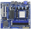
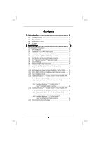
Motherboard Layout 11 1.4 I/O Panel 12 2 . Installation 13 Pre-installation Precautions 13 2.1 CPU Installation 14 2.2 Installation of CPU Fan and Heatsink 14 2.3 Installation of Memory Plug Feature and Operation Guide ....... 29 2.12 Driver Installation Guide 31 2.13 Installing Windows® 7 / 7 - ASRock 939A785GMH | User Manual - Page 4
UTILITY 36 3.1 Introduction 36 3.1.1 BIOS Menu Bar 36 3.1.2 Navigation Keys 37 3.2 Main Screen 37 3.3 OC Tweaker Exit Screen 56 4 . Software Support 57 4.1 Install Operating System 57 4.2 Support CD Information 57 4.2.1 Running Support CD 57 4.2.2 Drivers Menu 57 4.2.3 Utilities Menu 57 - ASRock 939A785GMH | User Manual - Page 5
design conforming to ASRock's commitment to quality and endurance. In this manual, chapter 1 and 2 contain introduction of the motherboard and step-by-step guide to the hardware installation. Chapter 3 and 4 contain the configuration guide to BIOS setup and information of the Support CD. Because the - ASRock 939A785GMH | User Manual - Page 6
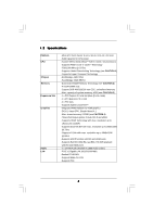
- Socket 939 for AMD AthlonTM 64FX / 64X2 / 64 processors - Supports AMD's Cool 'n' QuietTM Technology - FSB 1000 MHz (2.0 GT/s) - Supports Untied Overclocking Technology (see CAUTION 1) - Supports Hyper-Transport Technology - Northbridge: AMD 785G - Southbridge: AMD SB710 - Dual Channel DDR Memory - ASRock 939A785GMH | User Manual - Page 7
8Mb AMI BIOS - AMI Legal BIOS - Supports "Plug and Play" - ACPI 1.1 Compliance Wake Up Events - Supports jumperfree - SMBIOS 2.3.1 Support - VCCM, NB Voltage Multi-adjustment - Drivers, Utilities, AntiVirus Software (Trial Version), CyberLink MediaEspresso 6.5 Trial, ASRock Software Suite (CyberLink - ASRock 939A785GMH | User Manual - Page 8
visit our website: http://www.asrock.com WARNING Please realize that there is a certain risk involved with overclocking, including adjusting the setting in the BIOS, applying Untied Overclocking Technology, or using the thirdparty overclocking tools. Overclocking may affect your system stability - ASRock 939A785GMH | User Manual - Page 9
This motherboard supports Untied Overclocking Technology. Please read "Untied Overclocking Technology" on page 35 for details. 2. This motherboard supports Dual Channel Memory Technology. Before you implement Dual Channel Memory Technology, make sure to read the installation guide of memory modules - ASRock 939A785GMH | User Manual - Page 10
your overclocking record under the operating system and simplifies the complicated recording process of overclocking driver installed, you can easily enjoy the marvelous charging experience than ever. ASRock website: http://www.asrock.com/Feature/AppCharger/index.asp 11. Although this motherboard - ASRock 939A785GMH | User Manual - Page 11
Motherboard ) DVI_CON1 VGA1 SOCKET 939 RoHS HDMI1 eSATAII_1 Gigabit LAN USB 2.0 T: USB0 B: USB1 Top: RJ-45 939A785GMH IDE1 Top: CHA_FAN1 PCI2 FLOPPY1 LPT1 1 8Mb BIOS PANEL 1 PLED PWRBTN 1 HDLED Channel B: DDR3, DDR4; Black) 24 SPI Flash Memory (8Mb) 8 ATX Power Connector (ATXPWR1) 25 - ASRock 939A785GMH | User Manual - Page 12
Line In (No. 7) (No. 5) (No. 4) (No. 6) 2 V -- -- -- 4 V V -- -- 6 V V V -- 8 V V V V *** To support AC3 audio format with HDMI Audio under VistaTM, please install the XP HDMI audio driver. The driver is located under the path: ..\Drivers\NB Audio\REALTEK\XP64_XP(R1.68) And - ASRock 939A785GMH | User Manual - Page 13
, peripherals, and/or components. 1. Unplug the power cord from the wall socket before touching any component. 2. To avoid damaging the motherboard components due to static electricity, NEVER place your motherboard directly on the carpet or the like. Also remember to use a grounded wrist strap - ASRock 939A785GMH | User Manual - Page 14
Triangle To The Socket Corner Small Triangle STEP 4: Push Down And Lock The Socket Lever 2.2 Installation of CPU Fan and Heatsink After you install the CPU into this motherboard, it is For proper installation, please kindly refer to the instruction manuals of the CPU fan and the heatsink. 14 - ASRock 939A785GMH | User Manual - Page 15
2.3 Installation of Memory Modules (DIMM) 939A785GMH motherboard provides four 184-pin DDR (Double Data Rate) DIMM slots, and supports Dual Channel Memory Technology. For dual channel configuration, you always need to install identical (the same brand, speed, size and chip-type) DDR DIMM pair in the - ASRock 939A785GMH | User Manual - Page 16
matches the break on the slot. notch break notch break The DIMM only fits in one correct orientation. It will cause permanent damage to the motherboard and the DIMM if you force the DIMM into the slot at incorrect orientation. Step 3. Firmly insert the DIMM into the slot until the retaining - ASRock 939A785GMH | User Manual - Page 17
2.4 Expansion Slots (PCI and PCI Express Slots) There are 2 PCI slots and 2 PCI Express slots on this motherboard. PCI slots: PCI slots are used to install expansion cards that have the 32-bit PCI interface. PCIE slots: PCIE1 (PCIE x1 slot; White) is - ASRock 939A785GMH | User Manual - Page 18
after your system boots. If you haven't installed onboard VGA driver yet, please install onboard VGA driver from our support CD to your system and restart your computer. Then you can start to use multi monitor function on this motherboard. When you playback HDCP-protected video from Blu-ray (BD - ASRock 939A785GMH | User Manual - Page 19
motherboard supports surround display upgrade. With the internal VGA output support memory. If you do not adjust the BIOS setup, the default value of "Share Memory", [Auto], will disable D-Sub function when the add-on VGA card is inserted to this motherboard. 4. Install the onboard VGA driver Windows - ASRock 939A785GMH | User Manual - Page 20
four. For Windows® 7 / supported on this motherboard. To use HDCP function with this motherboard, you need to adopt the monitor that supports HDCP function as well. Therefore, you can enjoy the superior display quality with high-definition HDCP encryption contents. Please refer to below instruction - ASRock 939A785GMH | User Manual - Page 21
3450 series graphics processor and a motherboard based on an AMD 785G integrated chipset, all operating in a Windows® VistaTM environment. Please refer to below PCI Express graphics card support list for ATITM Hybrid CrossFireXTM. Vendor Chipset Model Driver ATI RADEON X2400PRO MSI RX2400 PRO - ASRock 939A785GMH | User Manual - Page 22
Step 7. Double-click "ATI Catalyst Control Center". Click "View", click "CrossFireTM", and then select the option "Enable CrossFireTM". View CrossFireTM Enable CrossFireTM Step 8. Click "Yes" to continue. Step 9. Click "OK" to save your change. Step 10. Reboot your system. Then you can freely - ASRock 939A785GMH | User Manual - Page 23
and pin3 on CLRCMOS1 for 5 seconds. However, please do not clear the CMOS right after you update the BIOS. If you need to clear the CMOS when you just finish updating the BIOS, you must boot up the system first, and then shut it down before you do the clear-CMOS action - ASRock 939A785GMH | User Manual - Page 24
to the motherboard connect the black end to the IDE devices 80-conductor ATA 66/100/133 cable Note: Please refer to the instruction of your IDE PORT 3) SATAII_5 (PORT 4) These five Serial ATAII (SATAII) connectors support SATAII or SATA hard disk for internal storage devices. The current SATAII - ASRock 939A785GMH | User Manual - Page 25
J_SENSE OUT2_R MIC2_R MIC2_L Besides four default USB 2.0 ports on the I/O panel, there are three USB 2.0 headers on this motherboard. Each USB 2.0 header can support two USB 2.0 ports. This is an interface for print port cable that allows convenient connection of printer devices. This header - ASRock 939A785GMH | User Manual - Page 26
the chassis must support HDA to function correctly. Please follow the instruction in our manual and chassis manual to install your BIOS Setup Utility. Enter Advanced Settings, and then select Chipset Configuration. Set the Front Panel Control option from [Auto] to [Enabled]. F. Enter Windows - ASRock 939A785GMH | User Manual - Page 27
1 2 3 4 Please connect the CPU fan cable to this connector and match the black wire to the ground pin. Though this motherboard provides 4-Pin CPU fan (Quiet Fan) support, the 3-Pin CPU fan still can work successfully even without the fan speed control function. If you plan to connect the 3-Pin - ASRock 939A785GMH | User Manual - Page 28
AMD SB710 south bridge chipset that supports Serial ATA (SATA) / Serial ATAII (SATAII) hard disks and RAID (RAID 0, RAID 1, RAID 10 and JBOD) functions. You may install SATA / SATAII hard disks on this motherboard for internal storage devices. This section will guide you to install the SATA / SATAII - ASRock 939A785GMH | User Manual - Page 29
is installed into system properly. The latest SATA / SATAII driver is available on our support website: www.asrock.com 4. Make sure to use the SATA power cable & data cable, which are from our motherboard package. 5. Please follow below instructions step by step to reduce the risk of HDD crash or - ASRock 939A785GMH | User Manual - Page 30
cable to (White) to the power supply 1x4-pin cable. the motherboard's SATAII connector. SATA power cable 1x4-pin power connector (White) Step attention, before you process the Hot Unplug: Please do follow below instruction sequence to process the Hot Unplug, improper procedure will cause the SATA - ASRock 939A785GMH | User Manual - Page 31
Mode" option to [RAID]. STEP 2: Make a SATA / SATAII Driver Diskette. A. Insert the ASRock Support CD into your optical drive to boot your system. B. During POST at the beginning of system boot-up, press key, and then a window for boot devices selection appears. Please select CD- ROM as - ASRock 939A785GMH | User Manual - Page 32
function, you need to check the RAID installation guide in the Support CD for proper configuration. Please refer to the BIOS RAID installation guide part of the document in the following path in the Support CD: .. \ RAID Installation Guide STEP 4: Install Windows® XP / XP 64-bit OS on your system - ASRock 939A785GMH | User Manual - Page 33
to set up "SATA Operation Mode" to [RAID] in BIOS first. Then, please set the RAID configuration by using the Windows RAID installation guide in the following path in the Support CD: .. \ RAID Installation Guide NOTE2. Currently, if you install Windows® 7 / 7 64-bit / VistaTM / VistaTM 64-bit on IDE - ASRock 939A785GMH | User Manual - Page 34
/ SATAII HDDs with NCQ and Hot Plug functions (AHCI mode) STEP 1: Set Up BIOS. A. Enter BIOS SETUP UTILITY Advanced screen Storage Configuration. B. Set the "SATA Operation Mode" option to [AHCI]. STEP 2: Install Windows® 7 / 7 64-bit / VistaTM / VistaTM 64-bit OS on your system. Using SATA - ASRock 939A785GMH | User Manual - Page 35
2.15 Untied Overclocking Technology This motherboard supports Untied Overclocking Technology, which means during overclocking, FSB enjoys better margin due to fixed PCI / PCIE buses. Before you enable Untied Overclocking function, please enter "Overclock Mode" option of BIOS setup to set the - ASRock 939A785GMH | User Manual - Page 36
the BIOS SETUP UTILITY to configure your system. The SPI Memory on the motherboard stores the BIOS SETUP UTILITY. You may run the BIOS SETUP UTILITY /date information OC Tweaker To set up overclocking features Advanced To set up the advanced BIOS features H/W Monitor To display current hardware - ASRock 939A785GMH | User Manual - Page 37
BIOS Version : 939A785GMH P1.00 Processor Type : Dual Core AMD Opteron (tm) Processor 180 (64bit) Processor Speed : 2400MHz Microcode Update : 20F32/4D L1 Cache Size : 256KB L2 Cache Size : 2048KB Total Memory DDR1 DDR2 DDR3 DDR4 : 256MB with 128MB shared memory Single-Channel Memory - ASRock 939A785GMH | User Manual - Page 38
Memory Configuration Memory Clock DRAM Voltage [Auto] [200] [100] [Auto] x12 2400 MHZ 1.400 V [Auto] [Auto] [Auto] [Auto] [Auto] [Auto] Overclocking may cause damage to your CPU and motherboard [Auto] by default. If it is set to [Manual], you may adjust the value of Processor Multiplier and - ASRock 939A785GMH | User Manual - Page 39
BIOS SETUP UTILITY Main OC Tweaker Advanced H/W Monitor Boot Security Exit CPU Configuration Overclock Mode CPU Memory Configuration [Auto] [200] [100] [Auto] x12 2400 MHZ 1.400 V [Manual] [x12 2400 MHz] [1.350 V] [Auto] [Auto] [Auto] Overclocking may cause damage to your CPU and motherboard - ASRock 939A785GMH | User Manual - Page 40
DRAM Voltage Use this to select DRAM voltage. Configuration options: [Auto], [2.60V] to [2.95V]. The default value is [Auto]. Memory Timing BIOS SETUP UTILITY OC Tweaker Memory Timing CAS Latency TRAS TRP TRCD TRRD TRC MA Timing Burst Length Bank Interleaving [Auto] [Auto] [Auto] [Auto] [Auto] [ - ASRock 939A785GMH | User Manual - Page 41
Bank Interleaving Interleaving allows memory accesses to be spread out over banks on the same node, or accross nodes, decreasing access contention. Chipset Settings Onboard GPU Clock Override This allows - ASRock 939A785GMH | User Manual - Page 42
section may cause the system to malfunction. ASRock Instant Flash ASRock Instant Flash is a BIOS flash utility embedded in Flash ROM. This convenient BIOS update tool allows you to update system BIOS without entering operating systems first like MS-DOS or Windows®. Just launch this tool and save - ASRock 939A785GMH | User Manual - Page 43
Advanced CPU Configuration Boot Failure Guard Cool' n' Quiet Memory Hole BIOS SETUP UTILITY [Enabled] [Auto] [Disabled] Enable or is [Auto]. Configuration options: [Auto], [Enabled] and [Disabled]. If you install Windows® 7 / VistaTM and want to enable this function, please set this item to [ - ASRock 939A785GMH | User Manual - Page 44
BIOS SETUP UTILITY Advanced Chipset Settings Onboard HD Audio Front Panel CD-In OnBoard Lan Primary Graphics Adapter [Auto] [Enabled] [Enabled] [Enabled] [PCI] Internal Graphics Mode Share Memory Audio. If you plan to use this motherboard to submit Windows® 7 / VistaTM logo test, please disable - ASRock 939A785GMH | User Manual - Page 45
CrossFireXTM feature. 3.4.3 ACPI Configuration BIOS SETUP UTILITY Advanced ACPI Settings Suspend To RAM Away Mode Support Restore on AC / Power Loss the feature Check Ready Bit. Away Mode Support Use this item to enable or disable Away Mode support under Windows® XP Media Center OS. The default - ASRock 939A785GMH | User Manual - Page 46
item to enable or disable ACPI HPET Table. The default value is [Disabled]. Please set this option to [Enabled] if you plan to use this motherboard to submit Windows® VistaTM certification. 46 - ASRock 939A785GMH | User Manual - Page 47
configuration for the device that you specify. We will use the "IDE1 Master" as the example in the following instruction, which can be applied to the configurations of "IDE1 Slave" as well. BIOS SETUP UTILITY Advanced IDE Master Device Vendor Size LBA Mode Block Mode PIO Mode Async DMA Ultra DMA - ASRock 939A785GMH | User Manual - Page 48
automatically detect the hard disk drive. After selecting the hard disk information into BIOS, use a disk utility, such as FDISK, to partition and format the new the LBA/Large mode for a hard disk > 512 MB under DOS and Windows; for Netware and UNIX user, select [Disabled] to disable the LBA/Large - ASRock 939A785GMH | User Manual - Page 49
3.4.5 PCIPnP Configuration BIOS SETUP UTILITY Advanced Advanced PCI / PnP Settings PCI Latency Timer PCI IDE BusMaster [32] [Enabled] Value in units of PCI clocks for PCI device latency - ASRock 939A785GMH | User Manual - Page 50
EPP Version ECP Mode DMA Channel Parallel Port IRQ PS/2 Port Type [Enabled] [3F8 / IRQ4] [Disabled] [378] [ECP + EPP] [1.9] [DMA3] [IRQ7] [Auto] Allow BIOS to Enable or Disable Floppy Controller. +F1 F9 F10 ESC Select Screen Select Item Change Option General Help Load Defaults Save and Exit Exit - ASRock 939A785GMH | User Manual - Page 51
Parallel Port Address Use this item to set the address for the onboard parallel port or disable it. Configuration options: [Disabled], [378], and [278]. Parallel Port Mode Use this item to set the operation mode of the parallel port. The default value is [ECP+EPP]. If this option is set to [ECP+EPP - ASRock 939A785GMH | User Manual - Page 52
Use this item to enable or disable the USB 2.0 support. Legacy USB Support Use this option to select legacy support for USB devices. There are four configuration options: [Enabled], [Auto], [Disabled] and [BIOS Setup Only]. The default value is [Enabled]. Please refer to below descriptions for - ASRock 939A785GMH | User Manual - Page 53
monitor the status of the hardware on your system, including the parameters of the CPU temperature, motherboard temperature, CPU fan speed, chassis fan speed, and the critical voltage. BIOS SETUP UTILITY Main OC Tweaker Advanced H/W Monitor Boot Security Exit Hardware Health Event Monitoring CPU - ASRock 939A785GMH | User Manual - Page 54
F1 General Help F9 Load Defaults F10 Save and Exit ESC Exit v02.54 (C) Copyright 1985-2005, American Megatrends, Inc. 3.6.1 Boot Settings Configuration BIOS SETUP UTILITY Boot Boot Settings Configuration Full Screen Logo AddOn ROM Display Boot Logo Boot From Onboard LAN Bootup Num-Lock [Enabled - ASRock 939A785GMH | User Manual - Page 55
option "Full Screen Logo". Configuration options: [Auto], [EUP], [Scenery] and [ASRock]. The default value is [Auto]. Boot From Onboard LAN Use this item to enable system. For the user password, you may also clear it. BIOS SETUP UTILITY Main OC Tweaker Advanced H/W Monitor Boot Security Exit - ASRock 939A785GMH | User Manual - Page 56
. Discard Changes When you select this option, it will pop-out the following message, "Discard changes?" Select [OK] to discard all changes. Load BIOS Defaults Load BIOS default values for all the setup questions. F9 key can be used for this operation. Load Performance Setup Default (IDE/SATA) This - ASRock 939A785GMH | User Manual - Page 57
install the necessary drivers to activate the devices. 4.2.3 Utilities Menu The Utilities Menu shows the applications software that the motherboard supports. Click on a specific item then follow the installation wizard to install it. 4.2.4 Contact Information If you need to contact ASRock or want to
-
 1
1 -
 2
2 -
 3
3 -
 4
4 -
 5
5 -
 6
6 -
 7
7 -
8
-
9
-
10
-
11
-
12
-
13
-
14
-
15
-
16
-
17
-
18
-
19
-
20
-
21
-
22
-
23
-
24
-
25
-
26
-
27
-
28
-
29
-
30
-
31
-
32
-
33
-
34
-
35
-
36
-
37
-
38
-
39
-
40
-
41
-
42
-
43
-
44
-
45
-
46
-
47
-
48
-
49
-
50
-
51
-
52
-
53
-
54
-
55
-
56
-
57
 |
 |

1
939A785GMH
User Manual
Version 1.0
Published August 2011
Copyright©2011 ASRock INC. All rights reserved.