ASRock 939A8X-M User Manual
ASRock 939A8X-M Manual
 |
View all ASRock 939A8X-M manuals
Add to My Manuals
Save this manual to your list of manuals |
ASRock 939A8X-M manual content summary:
- ASRock 939A8X-M | User Manual - Page 1
939A8X-M User Manual Version 1.1 Published July 2006 Copyright©2006 ASRock INC. All rights reserved. 1 - ASRock 939A8X-M | User Manual - Page 2
any form or by any means, except duplication of documentation by the purchaser for backup purpose, without written consent of ASRock Inc. Products and corporate names appearing in this manual may or may not be registered trademarks or copyrights of their respective companies, and are used only for - ASRock 939A8X-M | User Manual - Page 3
. Introduction 5 1.1 Package Contents 5 1.2 Specifications 6 1.3 Motherboard Layout 8 1.4 ASRock 8CH I/O 9 2 . Installation 10 Pre-installation Precautions 10 2.1 CPU Installation 11 2.2 Installation of CPU Fan and Heatsink 11 2.3 Installation of Memory Modules (DIMM 12 2.4 Expansion Slots - ASRock 939A8X-M | User Manual - Page 4
4 . Software Support 36 4.1 Install Operating System 36 4.2 Support CD Information 36 4.2.1 Running Support CD 36 4.2.2 Drivers Menu 36 4.2.3 Utilities Menu 36 4.2.4 Contact Information 36 APPENDIX: AMD's Cool 'n' QuietTM Technology ...... 37 4 - ASRock 939A8X-M | User Manual - Page 5
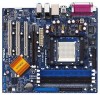
any modifications of this manual occur, the updated version will be available on ASRock website without further notice. You may find the latest memory and CPU support lists on ASRock website as well. ASRock website http://www.asrock.com 1.1 Package Contents 1 x ASRock 939A8X-M Motherboard (Micro ATX - ASRock 939A8X-M | User Manual - Page 6
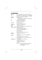
7.1 channels AC'97 Audio LAN: Speed: 802.3u (10/100 Ethernet), supports Wake-On-LAN Hardware Monitor: CPU temperature sensing Motherboard temperature sensing CPU overheat shutdown to protect CPU life (ASRock U-COP)(see CAUTION 2) CPU fan tachometer Chassis fan tachometer Voltage monitoring - ASRock 939A8X-M | User Manual - Page 7
CPU fan on the motherboard functions properly and unplug the power cord, then plug it back again. To improve heat dissipation, remember to spray thermal grease between the CPU Windows® 98 / ME. 5. For microphone input, this motherboard supports mono modes. For audio output, this motherboard supports - ASRock 939A8X-M | User Manual - Page 8
Game Port Header (GAME1) 20 JR1 Jumper / JL1 Jumper 21 Front Panel Audio Header (AUDIO1) 22 PCI Slots (PCI1 - 3) 23 AGP Slot (1.5V_AGP1) 24 Internal Audio Connector: CD1 (Black) 25 ATX Power Connector (ATXPWR1) 26 CPU Heatsink Retention Module 27 939-Pin CPU Socket 28 ATX 12V Connector (ATX12V1) 8 - ASRock 939A8X-M | User Manual - Page 9
1.4 ASRock 8CH I/O 1 13 12 11 2 3 6 4 7 5 8 10 9 1 Parallel Port 2 RJ-45 Port 3 table below for connection details in accordance with the type of speaker you use. TABLE for Audio Output Connection Audio Output Channels Front Speaker Rear Speaker Central / Bass (No. 7) (No. 4) (No. - ASRock 939A8X-M | User Manual - Page 10
, peripherals, and/or components. 1. Unplug the power cord from the wall socket before touching any component. 2. To avoid damaging the motherboard components due to static electricity, NEVER place your motherboard directly on the carpet or the like. Also remember to use a grounded wrist strap - ASRock 939A8X-M | User Manual - Page 11
Golden Triangle STEP 1: Lift Up The Socket Lever Socket Corner STEP 2 / STEP 3: STEP 4: Match The CPU Golden Triangle Push Down And Lock To The Socket Corner The Socket Lever 2.2 Installation of CPU Fan and Heatsink After you install the CPU into this motherboard, it is necessary to install - ASRock 939A8X-M | User Manual - Page 12
of Memory Modules (DIMM) 939A8X-M motherboard provides four 184-pin DDR (Double Data Rate) DIMM slots, and supports Dual Channel Memory Technology DIMM from the far side of CPU towards to the near side of CPU.) 1. If you want to install two different memory modules, for optimal compatibility and - ASRock 939A8X-M | User Manual - Page 13
matches the break on the slot. notch break notch break The DIMM only fits in one correct orientation. It will cause permanent damage to the motherboard and the DIMM if you force the DIMM into the slot at incorrect orientation. Step 3. Firmly insert the DIMM into the slot until the retaining - ASRock 939A8X-M | User Manual - Page 14
AGP Slots) There are 3 PCI slots and 1 AGP slot on 939A8X-M motherboard. PCI Slots: PCI slots are used to install expansion cards that have the 32-bit PCI interface. AGP slot: The AGP slot is used to install a graphics card. The ASRock AGP slot has a special design of clasp that can securely fasten - ASRock 939A8X-M | User Manual - Page 15
If JR1 and JL1 Jumpers are short, both the front panel and the rear panel audio connectors can work. Clear CMOS (CLRTC1) (see p.8, No. 10) 1_2 Default 2_3 clear the CMOS right after you update the BIOS. If you need to clear the CMOS when you just finish updating the BIOS, you must boot up the - ASRock 939A8X-M | User Manual - Page 16
ATA (SATA) connectors support SATA data cables for internal storage devices. The current SATA interface allows up to 1.5 Gb/s data transfer rate. Serial ATA (SATA) Data Cable Either end of the SATA data cable can be connected to the SATA hard disk or the SATA connector on the motherboard. 16 - ASRock 939A8X-M | User Manual - Page 17
to support 2 extra USB 2.0 ports. USB 2.0 Header (9-pin USB_H45) (see p.8, No. 15) USB_PWR P-5 P+5 GND DUMMY 1 GND P+4 P-4 USB_PWR ASRock 8CH 5V DUMMY 1 GND IRRX This header supports an optional wireless transmitting and receiving infrared module. Internal Audio Connectors (4-pin CD1) (CD1: - ASRock 939A8X-M | User Manual - Page 18
to this connector and match the black wire to the ground pin. CPU Fan Connector (3-pin CPU_FAN1) (see p.8 item 5) CPU_FAN_SPEED +12V GND Please connect a CPU fan cable to this connector and match the black wire to the ground pin. ATX Power Connector (20-pin ATXPWR1) (see p.8 item 25) Please - ASRock 939A8X-M | User Manual - Page 19
) Hard Disks Installation This motherboard supports Serial ATA (SATA) hard disks and RAID functions. This section will guide you to install the SATA hard disks. STEP 1: Install the SATA hard disks into the drive bays of your chassis. STEP 2: Connect the SATA power cable to the SATA hard disk. STEP - ASRock 939A8X-M | User Manual - Page 20
Operation in "RAID" Mode If you want to install Windows 2000, Windows XP, or Windows XP 64-bit OS on your SATA HDDs, you will need to make a SATA driver before you start the OS installation. STEP 1: Insert the ASRock Support CD into your optical drive to boot your system. (Do NOT insert any floppy - ASRock 939A8X-M | User Manual - Page 21
the BIOS SETUP UTILITY to configure your system. The Flash Memory on the motherboard stores the BIOS SETUP UTILITY. You may run the BIOS SETUP off and then back on. Because the BIOS software is constantly being updated, the following BIOS setup screens and descriptions are for reference purpose - ASRock 939A8X-M | User Manual - Page 22
Exit System Overview System Time System Date [17:00:09] [Tue 04/26/2005] BIOS Version : 939A8X-M BIOS P1.0 Processor Type : AMD Athlon(tm) 64 Processor 3400+ Processor Speed : 2200 MHz L1 Cache Size : 128KB L2 Cache Size : 1024KB Total Memory DIMM 1 DIMM 2 DIMM 3 DIMM 4 : 512MB Dual-Channel - ASRock 939A8X-M | User Manual - Page 23
BIOS SETUP UTILITY Advanced CPU Configuration CPU Host Frequency Actual Frequency (MHz) Boot Failure Guard Spread Spectrum Cool' n' Quiet [Auto] [200] [Enabled] [Disabled] [Enabled] Processor Maximum Multiplier Processor Maximum Voltage Multiplier/Voltage Change Memory Clock Flexibility - ASRock 939A8X-M | User Manual - Page 24
Frequency While entering setup, BIOS auto detects the present CPU host frequency of this motherboard. The actual CPU host frequency will show Change Processor Multiplier Processor Voltage Memory Clock Flexibility Option Burst Length CAS Latency (CL) TRCD x11 1.550 V [Manual] [x8] [1.500V] [Auto - ASRock 939A8X-M | User Manual - Page 25
This item will show when "Multiplier/Voltage Change" is set to [Manual]; otherwise, it will be hidden. You may set the value from [1. default value of this option is [Disabled]. It will allow better tolerance for memory compatibility when it is set to [Enabled]. Burst Length Burst length can be set - ASRock 939A8X-M | User Manual - Page 26
BIOS SETUP UTILITY Chipset Settings OnBoard LAN OnBoard AC97 Audio [Enabled] [Auto] AGP Aperture Size AGP Data Rate AGP Fast Write Primary Graphics Adapter [64 MB to enable or disable the feature of AGP fast write protocol support. Primary Graphics Adapter This item will switch the PCI Bus - ASRock 939A8X-M | User Manual - Page 27
VCCM voltage between [2.72V] and [2.61V]. 3.3.3 ACPI Configuration Advanced BIOS SETUP UTILITY ACPI Settings Suspend To RAM Repost Video on STR Resume Restore on STR resume. It is recommended to enable this feature under Microsoft Windows 98 / ME. (STR refers to suspend to RAM.) Ring-In Power - ASRock 939A8X-M | User Manual - Page 28
SATA Controller Use this item to enable or disable the "OnBoard SATA Controller" feature. SATA Operation Mode Use this item to adjust SATA Operation instruction, which can be applied to the configurations of "Primary IDE Slave", "Secondary IDE Master", and "Secondary IDE Slave" as well. BIOS - ASRock 939A8X-M | User Manual - Page 29
automatically detect the hard disk drive. After selecting the hard disk information into BIOS, use a disk utility, such as FDISK, to partition and format the item to select the LBA/Large mode for a hard disk > 512 MB under DOS and Windows; for Netware and UNIX user, select [Disabled] to disable the - ASRock 939A8X-M | User Manual - Page 30
PCI IDE BusMaster feature. 3.3.6 Floppy Configuration In this section, you may configure the type of your floppy drive. BIOS SETUP UTILITY Advanced Floppy Configuration Floppy A Floppy B [1.44 MB 312"] [Disabled] Select the type of floppy drive connected to the system. +F1 F9 F10 ESC Select - ASRock 939A8X-M | User Manual - Page 31
Channel Parallel Port IRQ OnBoard Game Port OnBoard MIDI Port [Enabled] [3F8 / IRQ4] [Disabled] [378] [ECP + EPP] [1.9] [DMA3] [IRQ7] [Enabled] [Disabled] Allow BIOS to Enable or Disable Floppy Controller. +F1 F9 F10 ESC Select Screen Select Item Change Option General Help Load Defaults Save and - ASRock 939A8X-M | User Manual - Page 32
the MIDI Port or disable it. Configuration options: [Disabled], [300], and [330]. 3.3.8 USB Configuration BIOS SETUP UTILITY Advanced USB Configuration USB Controller USB 2.0 Support Legacy USB Support [Enabled] [Enabled] [Disabled] To enable or disable the onboard USB controllers. +F1 F9 F10 - ASRock 939A8X-M | User Manual - Page 33
you to monitor the status of the hardware on your system, including the parameters of the CPU temperature, motherboard temperature, CPU fan speed, chassis fan speed, and the critical voltage. BIOS SETUP UTILITY Main Advanced H/W Monitor Boot Security Exit Hardware Health Event Monitoring - ASRock 939A8X-M | User Manual - Page 34
may set or change the supervisor/user password for the system. For the user password, you may also clear it. Main Advanced BIOS SETUP UTILITY H/W Monitor Boot Security Settings Supervisor Password : Not Installed User Password : Not Installed Change Supervisor Password Change User Password - ASRock 939A8X-M | User Manual - Page 35
and exit setup?" Select [OK] to save the changes and exit the BIOS SETUP UTILITY. Discard Changes and Exit When you select this option, it message, "Discard changes and exit setup?" Select [OK] to exit the BIOS SETUP UTILITY without saving any changes. Discard Changes When you select this option - ASRock 939A8X-M | User Manual - Page 36
available devices drivers including ASRock Express GbL PCI Express LAN card driver if the system detects the installed devices. Please install the necessary drivers to activate the devices. 4.2.3 Utilities Menu The Utilities Menu shows the applications software that the motherboard supports. Click - ASRock 939A8X-M | User Manual - Page 37
feature, please make sure to install "AMD Processor Driver" from the "Support CD" first. If you are using Windows 2000/XP operating system, please follow the instruction below to enable AMD's Cool 'n' QuietTM technology: 1. From the Windows 2000/XP operating system, click the Start button. Select
-
 1
1 -
 2
2 -
 3
3 -
 4
4 -
 5
5 -
 6
6 -
 7
7 -
8
-
9
-
10
-
11
-
12
-
13
-
14
-
15
-
16
-
17
-
18
-
19
-
20
-
21
-
22
-
23
-
24
-
25
-
26
-
27
-
28
-
29
-
30
-
31
-
32
-
33
-
34
-
35
-
36
-
37
 |
 |
1
939A8X-M
User Manual
Version 1.1
Published July 2006
Copyright©2006 ASRock INC. All rights reserved.