ASRock 939Dual-SATA2 User Manual
ASRock 939Dual-SATA2 Manual
 |
View all ASRock 939Dual-SATA2 manuals
Add to My Manuals
Save this manual to your list of manuals |
ASRock 939Dual-SATA2 manual content summary:
- ASRock 939Dual-SATA2 | User Manual - Page 1
939Dual-SATA2 User Manual Version 1.1 Published July 2006 Copyright©2006 ASRock INC. All rights reserved. 1 - ASRock 939Dual-SATA2 | User Manual - Page 2
of business, loss of data, interruption of business and the like), even if ASRock has been advised of the possibility of such damages arising from any defect or error in the manual or product. This device complies with Part 15 of the FCC Rules. Operation is subject to the following two conditions - ASRock 939Dual-SATA2 | User Manual - Page 3
Installation of Memory Modules (DIMM 12 2.4 Expansion Slots (Future CPU Port, PCI Slots, PCIE Slots, and AGP Slot 14 2.5 Jumpers Setup 16 2.6 Surround Display Feature 16 2.7 Onboard Headers and Connectors 17 2.8 Serial ATA (SATA) Hard Disks Installation 20 2.9 Making a SATA Driver Diskette For - ASRock 939Dual-SATA2 | User Manual - Page 4
3.6 Security Screen 37 3.7 Exit Screen 38 4 . Software Support 39 4.1 Install Operating System 39 4.2 Support CD Information 39 4.2.1 Running Support CD 39 4.2.2 Drivers Menu 39 4.2.3 Utilities Menu 39 4.2.4 Contact Information 39 APPENDIX: AMD's Cool 'n' QuietTM Technology ...... 40 4 - ASRock 939Dual-SATA2 | User Manual - Page 5
latest memory and CPU support lists on ASRock website as well. ASRock website http://www.asrock.com 1.1 Package Contents 1 x ASRock 939Dual-SATA2 Motherboard (ATX Form Factor: 12.0-in x 9.6-in, 30.5 cm x 24.4 cm) 1 x ASRock 939Dual-SATA2 Quick Installation Guide 1 x ASRock 939Dual-SATA2 Support CD - ASRock 939Dual-SATA2 | User Manual - Page 6
x 24.4 cm CPU: 939-Pin Socket Supporting AMD AthlonTM 64 / 64FX Processor Supports AMD's Cool 'n' QuietTM Technology (see CAUTION 1) Chipsets: North Bridge: ULi® M1695 chipset For 939-Pin CPU, FSB @ 1 GHz / 2.0 GT/s South Bridge: ULi® M1567 chipset, supports SATA 1.5Gb/s Memory: 4 x DDR - ASRock 939Dual-SATA2 | User Manual - Page 7
Microsoft® Windows® 2000 / XP / XP 64-bit compliant CAUTION! 1. For power-saving's sake, it is strongly recommended to enable AMD's Cool 'n' QuietTM technology under Windows system. See APPENDIX on page 40 to enable AMD's Cool 'n' QuietTM technology. 2. This motherboard supports Dual Channel Memory - ASRock 939Dual-SATA2 | User Manual - Page 8
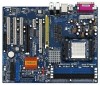
CD1 ULi M1695 Chipset 1 J11 LAN PHY FUTURE_CPU_PORT1 PCIE 1 1 J10 1 J9 PCI EXPRESS SATAII SATAII_1 PCIE 2 939Dual-SATA2 ULi M1567 1.5V_AGP1 Chipset AGP8X JMicron JMB360 SATA SATA2 SATA1 AUDIO CODEC JR1 JL1 1 1 AUDIO1 GAME1 PCI 1 USB2.0 PCI 2 PCI 3 IR1 1 2Mb BIOS ATA133 - ASRock 939Dual-SATA2 | User Manual - Page 9
1.4 ASRock 8CH I/O 1 13 12 11 2 3 6 4 7 5 8 10 9 1 Parallel Port 2 RJ-45 Port 3 Side Speaker (Gray) 4 Rear Speaker (Black) 5 Central / Bass (Orange) 6 Line In (Light Blue) *7 Front Speaker ( - ASRock 939Dual-SATA2 | User Manual - Page 10
any motherboard settings. Before you install or remove any component, ensure that the power is switched off or the power cord is detached from the power supply. Failure to do so may cause severe damage to the motherboard, peripherals, and/or components. 1. Unplug the power cord from the wall socket - ASRock 939Dual-SATA2 | User Manual - Page 11
Golden Triangle STEP 1: Lift Up The Socket Lever Socket Corner STEP 2 / STEP 3: STEP 4: Match The CPU Golden Triangle Push Down And Lock To The Socket Corner The Socket Lever 2.2 Installation of CPU Fan and Heatsink After you install the CPU into this motherboard, it is necessary to install - ASRock 939Dual-SATA2 | User Manual - Page 12
2.3 Installation of Memory Modules (DIMM) 939Dual-SATA2 motherboard provides four 184-pin DDR (Double Data Rate) DIMM slots, and supports Dual Channel Memory Technology. For dual channel configuration, you always need to install identical (the same brand, speed, size and chip-type) DDR DIMM pair in - ASRock 939Dual-SATA2 | User Manual - Page 13
Installing a DIMM Please make sure to disconnect power supply before adding or removing DIMMs or the system components. The DIMM only fits in one correct orientation. It will cause permanent damage to the motherboard and the DIMM if you force the DIMM into the slot at incorrect orientation. Step - ASRock 939Dual-SATA2 | User Manual - Page 14
Port allows you to upgrade your AMD 939-Pin CPU to AMD 940-Pin CPU by installing an add-on ASRock M2CPU Board into this future CPU Port on 939DualSATA2 motherboard. Before you upgrade the 939-Pin CPU to the 940-Pin (M2) CPU, it is necessary to adjust the jumper settings for those required jumpers on - ASRock 939Dual-SATA2 | User Manual - Page 15
make sure that the power supply is switched off or the power cord is unplugged. Please read the documentation of the expansion card and make necessary hardware settings for the card before you start the installation. Step 2. Remove the system unit cover (if your motherboard is already installed in - ASRock 939Dual-SATA2 | User Manual - Page 16
cord from the power supply. After waiting for 15 seconds, use a jumper cap to short pin2 and pin3 on CLRTC1 for 5 seconds. However, please do not clear the CMOS right after you update the BIOS. If you need to clear the CMOS when you just finish updating the BIOS, you must boot up the system first - ASRock 939Dual-SATA2 | User Manual - Page 17
use only one IDE device on this motherboard, please set the IDE device as "Master". Please refer to the instruction of your IDE device vendor for the (SATA) (SATA1: see p.8 No. 14) (SATA2: see p.8 No. 13) SATA2 connectors support SATA data cables for internal storage devices. The current SATA - ASRock 939Dual-SATA2 | User Manual - Page 18
SATA power cable to the power connector of the power supply. USB 2.0 Header (9-pin USB67) (see p.8 No. 21) USB_PWR P-6 P+6 GND DUMMY 1 GND P+7 P-7 USB_PWR ASRock 1 GND IRRX CD-R GND GND CD-L CD1 This header supports an optional wireless transmitting and receiving infrared module. This connector - ASRock 939Dual-SATA2 | User Manual - Page 19
19) CPU Fan Connector (3-pin CPU_FAN1) (see p.8 No. 3) ATX Power Connector (20-pin ATXPWR1) (see p.8 No. 2) PLED+ PLEDPWRBTN# GND 1 DUMMY RESET# GND CPU fan cable to this connector and match the black wire to the ground pin. Please connect an ATX power supply to this connector. ATX 12V Power - ASRock 939Dual-SATA2 | User Manual - Page 20
in "RAID" Mode If you want to install Windows 2000, Windows XP, or Windows XP 64-bit OS on your SATA HDDs, you will need to make a SATA driver diskette before you start the OS installation. STEP 1: Insert the ASRock Support CD into your optical drive to boot your system. (Do NOT insert any floppy - ASRock 939Dual-SATA2 | User Manual - Page 21
path in the Support CD: .. \ Information \ Manual \ RAID Installation Guide \ English.pdf 2.10 SATA Operating in "non-RAID" Mode If you want to install Windows 2000, Windows XP, or Windows XP 64-bit OS on your SATA HDDs operating in non-RAID mode, you don't need to make a SATA driver diskette before - ASRock 939Dual-SATA2 | User Manual - Page 22
SETUP UTILITY to configure your system. The Flash Memory on the motherboard stores the BIOS SETUP UTILITY. You may run the BIOS SETUP UTILITY when you start up the computer. Please press during the Power-On-Self-Test (POST) to enter the BIOS SETUP UTILITY, otherwise, POST will continue with its - ASRock 939Dual-SATA2 | User Manual - Page 23
00:09] [Tue 06/28/2005] BIOS Version : 939Dual-SATA2 BIOS P1.0 Processor Type : AMD Athlon(tm) 64 Processor 3500+ (64 bit supported) Processor Speed : 2200 MHz Microcode Update : 10FF0/41 L1 Cache Size : 128KB L2 Cache Size : 1024KB Total Memory DDR 1 DDR 2 DDR 3 DDR 4 : 512MB Dual-Channel Memory - ASRock 939Dual-SATA2 | User Manual - Page 24
you may upgrade your AMD 939-Pin CPU to AMD 940-Pin (M2) CPU by installing an add-on ASRock M2CPU Board into future CPU Port on this motherboard 3.3 Advanced Screen In this section, you may set the configurations for the following items: CPU Configuration, Chipset Configuration, ACPI Configuration - ASRock 939Dual-SATA2 | User Manual - Page 25
3.3.1 CPU Configuration BIOS SETUP UTILITY Advanced CPU Configuration Overclock Mode CPU Frequency (MHz) PCIE Frequency (MHz) Boot Failure Guard Spread Spectrum Cool' n' Quiet Processor Maximum Multiplier Processor Maximum Voltage Multiplier/Voltage Change Memory Clock Flexibility Option Burst - ASRock 939Dual-SATA2 | User Manual - Page 26
Advanced BIOS SETUP UTILITY CPU Configuration Overclock Mode CPU Frequency (MHz) PCIE Frequency (MHz) Boot Failure Guard Spread Spectrum Cool' n' Quiet Processor Maximum Multiplier Processor Maximum Voltage Multiplier/Voltage Change Processor Multiplier Processor Voltage Memory Clock Flexibility - ASRock 939Dual-SATA2 | User Manual - Page 27
BIOS SETUP UTILITY Advanced Chipset Settings OnBoard LAN OnBoard AC97 Audio [Enabled] [Auto] AGP Aperture Size AGP Data Rate AGP Fast Write Primary Graphics Adapter [64MB] [4X] [Disabled] [PCI] CPU - NB Link Speed CPU of the PCI memory address range used for graphics memory. It is support. 27 - ASRock 939Dual-SATA2 | User Manual - Page 28
PCI], [PCIE] and [AGP]. CPU - NB Link Speed This feature allows you selecting CPU to NB BIOS SETUP UTILITY Advanced ACPI Settings Suspend To RAM Repost Video on STR Resume Restore on AC / Power Loss Ring-In Power On PCI Devices Power On PS / 2 Keyboard Power On RTC Alarm Power On [Auto] [No] [Power - ASRock 939Dual-SATA2 | User Manual - Page 29
suspend to RAM.) Restore on AC/Power Loss This allows you to set the power state after an unexpected AC/power loss. If [Power Off] is selected, the AC/power remains off when the power recovers. If [Power On] is selected, the AC/power resumes and the system starts to boot up when the power recovers - ASRock 939Dual-SATA2 | User Manual - Page 30
value of this option is [IDE]. Configuration options: [IDE], [SATA]. IDE Device Configuration You may set the IDE configuration for the device that you specify. We will use the "Primary IDE Master" as the example in the following instruction, which can be applied to the configurations of "Primary - ASRock 939Dual-SATA2 | User Manual - Page 31
BIOS SETUP UTILITY Advanced Primary IDE Master Device Vendor Size LBA Mode Block Mode PIO Mode Async DMA Ultra DMA S.M.A.R.T. :Hard Disk :MAXTOR 6L080J4 :80.0 GB :Supported :16Sectors :4 :MultiWord DMA-2 :Ultra DMA-6 :Supported 512 MB under DOS and Windows; for Netware and UNIX item to set the PIO - ASRock 939Dual-SATA2 | User Manual - Page 32
Use this item to enable 32-bit access to maximize the IDE hard disk data transfer rate. 3.3.5 PCIPnP Configuration BIOS SETUP UTILITY Advanced Advanced PCI / PnP Settings WARNING: Setting wrong values in below sections may cause system to malfunction. Value in units of PCI clocks for PCI device - ASRock 939Dual-SATA2 | User Manual - Page 33
. 3.3.7 Super IO Configuration BIOS SETUP UTILITY Advanced Configure Super IO Chipset OnBoard Floppy Controller Serial Port enable or disable floppy drive controller. Serial Port Address Use this item to set the address for the onboard serial port or disable it. Configuration options: [Disabled - ASRock 939Dual-SATA2 | User Manual - Page 34
or disable it. Configuration options: [Disabled], [378], and [278]. Parallel Port Mode Use this item to set the operation mode of the parallel port. The default value is [ECP+EPP]. If this option is set to [ECP+EPP], it will show the EPP version in the following item, "EPP Version". Configuration - ASRock 939Dual-SATA2 | User Manual - Page 35
the parameters of the CPU temperature, motherboard temperature, CPU fan speed, chassis fan speed, and the critical voltage. BIOS SETUP UTILITY Main Advanced H/W Monitor Boot Security Exit Hardware Health Event Monitoring CPU Temperature M / B Temperature CPU Fan Speed Chassis Fan Speed - ASRock 939Dual-SATA2 | User Manual - Page 36
devices on your system for you to configure the boot settings and the boot priority. Main Advanced BIOS SETUP UTILITY H/W Monitor Boot Security Exit Boot Settings Boot Settings Configuration 1st Boot Device 2nd Boot Device 3rd Boot Device Removable Drives [1st Floppy Device] [HDD: PM - ASRock 939Dual-SATA2 | User Manual - Page 37
supervisor/user password for the system. For the user password, you may also clear it. BIOS SETUP UTILITY Main Advanced H/W Monitor Boot Security Exit Security Settings Supervisor Password : Not Installed User Password : Not Installed Change Supervisor Password Change User Password Clear - ASRock 939Dual-SATA2 | User Manual - Page 38
3.7 Exit Screen Main BIOS SETUP UTILITY Advanced H/W Monitro Boot Security Exit Exit Options Save Changes and "Save configuration changes and exit setup?" Select [OK] to save the changes and exit the BIOS SETUP UTILITY. Discard Changes and Exit When you select this option, it will pop-out the - ASRock 939Dual-SATA2 | User Manual - Page 39
Install Operating System This motherboard supports various Microsoft® Windows® operating systems: 2000 / XP / XP 64-bit. Because motherboard settings and hardware options vary, use the setup procedures in this chapter for general reference only. Refer to your OS documentation for more information - ASRock 939Dual-SATA2 | User Manual - Page 40
sure to install "AMD Processor Driver" from the "Support CD" first. If you are using Windows 2000/XP operating system, please follow the instruction below to enable AMD's Cool 'n' QuietTM technology: 1. From the Windows 2000/XP operating system, click the Start button. Select Settings, then Control
-
 1
1 -
 2
2 -
 3
3 -
 4
4 -
 5
5 -
 6
6 -
 7
7 -
8
-
9
-
10
-
11
-
12
-
13
-
14
-
15
-
16
-
17
-
18
-
19
-
20
-
21
-
22
-
23
-
24
-
25
-
26
-
27
-
28
-
29
-
30
-
31
-
32
-
33
-
34
-
35
-
36
-
37
-
38
-
39
-
40
 |
 |

1
939Dual-SATA2
User Manual
Version 1.1
Published July 2006
Copyright©2006 ASRock INC. All rights reserved.