ASRock 939NF4G-VSTA User Manual
ASRock 939NF4G-VSTA Manual
 |
View all ASRock 939NF4G-VSTA manuals
Add to My Manuals
Save this manual to your list of manuals |
ASRock 939NF4G-VSTA manual content summary:
- ASRock 939NF4G-VSTA | User Manual - Page 1
939NF4G-VSTA User Manual Version 1.2 Published July 2006 Copyright©2006 ASRock INC. All rights reserved. 1 - ASRock 939NF4G-VSTA | User Manual - Page 2
any form or by any means, except duplication of documentation by the purchaser for backup purpose, without written consent of ASRock Inc. Products and corporate names appearing in this manual may or may not be registered trademarks or copyrights of their respective companies, and are used only for - ASRock 939NF4G-VSTA | User Manual - Page 3
Installation Guide 23 2.12 HDMR Card and Driver Installation 24 2.13 Installing Windows® 2000 / XP / XP 64-bit / VistaTM Without RAID Functions 24 2.14 Installing Windows® 2000 / XP / XP 64-bit / VistaTM With RAID Functions 24 2.15 Untied Overclocking Technology 25 3 . BIOS SETUP UTILITY 26 - ASRock 939NF4G-VSTA | User Manual - Page 4
3.5.1 Boot Settings Configuration 39 3.6 Security Screen 40 3.7 Exit Screen 41 4 . Software Support 42 4.1 Install Operating System 42 4.2 Support CD Information 42 4.2.1 Running Support CD 42 4.2.2 Drivers Menu 42 4.2.3 Utilities Menu 42 4.2.4 Contact Information 42 APPENDIX: AMD's Cool - ASRock 939NF4G-VSTA | User Manual - Page 5
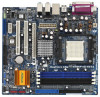
and CPU support lists on ASRock website as well. ASRock website http://www.asrock.com 1.1 Package Contents 1 x ASRock 939NF4G-VSTA Motherboard (Micro ATX Form Factor: 9.6-in x 8.8-in, 24.4 cm x 22.4 cm) 1 x ASRock 939NF4G-VSTA Quick Installation Guide 1 x ASRock 939NF4G-VSTA Support CD 1 x Ultra - ASRock 939NF4G-VSTA | User Manual - Page 6
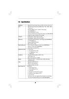
LAN Rear Panel I/O - Micro ATX Form Factor: 9.6-in x 8.8-in, 24.4 cm x 22.4 cm - 939-Pin Socket Supporting AMD AthlonTM 64 / 64FX / 64X2 Processors - Supports x DDR DIMM slots - Support DDR400/333/266 - Max. capacity: 4GB - CPU Frequency Stepless Control (see CAUTION 4) - ASRock U-COP (see CAUTION - ASRock 939NF4G-VSTA | User Manual - Page 7
- Front panel audio connector - 2 x USB 2.0 headers (support 4 USB 2.0 ports) (see CAUTION 8) - 4Mb AMI BIOS - AMI Legal BIOS - Supports "Plug and Play" - ACPI 1.1 Compliance Wake Up Events - Supports jumperfree - SMBIOS 2.3.1 Support - Drivers, Utilities, AntiVirus Software (Trial Version) - CPU - ASRock 939NF4G-VSTA | User Manual - Page 8
'n' QuietTM technology under Windows system. See APPENDIX on page 43 to enable AMD's Cool 'n' QuietTM technology. Since not all K8 939-pin CPU can support AMD's Cool 'n' QuietTM technology, please check AMD's website for details. 2. This motherboard supports Untied Overclocking Technology. Please - ASRock 939NF4G-VSTA | User Manual - Page 9
who purchase this motherboard and plan to submit Windows® VistaTM Premium and with total system memory size 512MB and plan to submit Windows® VistaTM Basic logo, please adjust the shared memory size system memory size above 512MB and plan to submit Windows® VistaTM Premium and Basic logo, the shared - ASRock 939NF4G-VSTA | User Manual - Page 10
1.4 Motherboard Layout 1 2 34 PS2 Mouse 1 PS2_USB_PW1 ATX12V1 5 22.4cm (8.8-in) Dual Channel FSB1GHz 6 7 DDR400 PS2 Keyboard IDE2 PARALLEL PORT SOCKET 939 VGA1 1 31 30 29 28 27 Top: LINE IN Center: FRONT Bottom: MIC IN Top: REAR SPK Center: SIDE SPK Bottom: CTR BASS USB 2.0 T: USB2 - ASRock 939NF4G-VSTA | User Manual - Page 11
1.5 HD 8CH I/O 1 2 3 6 4 7 5 8 13 12 11 10 9 1 Parallel Port 2 RJ-45 Port 3 Side Speaker (Gray) 4 Rear Speaker (Black) 5 Central / Bass (Orange) 6 Line In (Light Blue) *7 Front Speaker (Lime) 8 Microphone (Pink) 9 USB 2.0 Ports (USB01) 10 USB 2.0 Ports (USB23) 11 VGA Port 12 PS/2 - ASRock 939NF4G-VSTA | User Manual - Page 12
2. Installation 939NF4G-VSTA is a Micro ATX form factor (9.6-in x 8.8-in, 24.4 cm x 22.4 cm) motherboard. Before you install the motherboard, study the configuration of your chassis to ensure that the motherboard fits into it. Pre-installation Precautions Take note of the following precautions - ASRock 939NF4G-VSTA | User Manual - Page 13
Triangle Push Down And Lock To The Socket Corner The Socket Lever 2.2 Installation of CPU Fan and Heatsink After you install the CPU into this motherboard, it is necessary to install a larger proper installation, please kindly refer to the instruction manuals of the CPU fan and the heatsink. 13 - ASRock 939NF4G-VSTA | User Manual - Page 14
2.3 Installation of Memory Modules (DIMM) 939NF4G-VSTA motherboard provides four 184-pin DDR (Double Data Rate) DIMM slots, and supports Dual Channel Memory Technology. For dual channel configuration, you always need to install identical (the same brand, speed, size and chip-type) DDR DIMM pair - ASRock 939NF4G-VSTA | User Manual - Page 15
matches the break on the slot. notch break notch break The DIMM only fits in one correct orientation. It will cause permanent damage to the motherboard and the DIMM if you force the DIMM into the slot at incorrect orientation. Step 3. Firmly insert the DIMM into the slot until the retaining - ASRock 939NF4G-VSTA | User Manual - Page 16
and 1 HDMR slot on 939NF4G-VSTA motherboard. PCIE Slots: PCIE1 ( cards, such as Gigabit LAN card, SATA2 card, etc used to insert an ASRock HDMR card with Monitor Feature This motherboard supports Multi Monitor upgrade. BIOS, you can install VGA cards and VGA card drivers to enjoy multi-monitors. 16 - ASRock 939NF4G-VSTA | User Manual - Page 17
the CMOS right after you update the BIOS. If you need to clear the CMOS when you just finish updating the BIOS, you must boot up the system Placing jumper caps over the headers and connectors will cause permanent damage of the motherboard! • Floppy Connector (33-pin FLOPPY1) (see p.10 No. 21) - ASRock 939NF4G-VSTA | User Manual - Page 18
one IDE device on this motherboard, please set the IDE device as "Master". Please refer to the instruction of your IDE device vendor p.10, No. 12) SATAII_2 SATAII_1 These Serial ATA II (SATA II) connectors support SATA II or SATA hard disk for internal storage devices. The current SATA II - ASRock 939NF4G-VSTA | User Manual - Page 19
allows convenient connection and control of audio devices. 1. High Definition Audio supports Jack Sensing, but the panel wire on the chassis must support HDA to function correctly. Please follow the instruction in our manual and chassis manual to install your system. 2. If you use AC'97 audio - ASRock 939NF4G-VSTA | User Manual - Page 20
FAN_SPEED_CONTROL Please connect the CPU fan cable to this connector and match the black wire to the ground pin. Though this motherboard provides 4-Pin CPU fan (Quiet Fan) support, the 3-Pin CPU fan still can work successfully even without the fan speed control function. If you plan to connect - ASRock 939NF4G-VSTA | User Manual - Page 21
RRXD1 DDTR#1 DDSR#1 CCTS#1 1 RRI#1 RRTS#1 GND TTXD1 DDCD#1 Connect a Game cable to this header if the Game port bracket is installed. This COM1 header supports a serial port module. c s 21 - ASRock 939NF4G-VSTA | User Manual - Page 22
guide. Some default setting of SATAII hard disks may not be at SATAII mode, which operate with the best performance. In order to enable SATAII function, please follow the below instruction 's website for details: http://www.hitachigst.com/hdd/support/download.htm The above examples are just for your - ASRock 939NF4G-VSTA | User Manual - Page 23
2.10 Hot Plug and Hot Swap Functions for SATA / SATAII HDDs This motherboard supports Hot Plug and Hot Swap functions for SATA / SATAII Devices. NOTE What 11 Driver Installation Guide To install the drivers to your system, please insert the support CD to your optical drive first. Then, the drivers - ASRock 939NF4G-VSTA | User Manual - Page 24
motherboard. Please make sure that the HDMR card is completely seated on the slot. 2. Install HDMR card driver from our support CD to your system. 3. Reboot your system. 2.13 Installing Windows® 2000 / Windows® XP / Windows® XP 64-bit / Windows SATAII Driver Diskette. A. Insert the ASRock Support - ASRock 939NF4G-VSTA | User Manual - Page 25
drivers into the floppy diskette. STEP 2: Set Up BIOS. A. Enter BIOS Support CD, "Guide to nVidia RAID Utility for Windows", which is located in the folder at the following path: .. \Information\Manual\RAID Utility for Windows Guide 2.15 Untied Overclocking Technology This motherboard supports - ASRock 939NF4G-VSTA | User Manual - Page 26
SETUP UTILITY 3.1 Introduction This section explains how to use the BIOS SETUP UTILITY to configure your system. The Flash Memory on the motherboard stores the BIOS SETUP UTILITY. You may run the BIOS SETUP UTILITY when you start up the computer. Please press during the Power-On-Self-Test (POST - ASRock 939NF4G-VSTA | User Manual - Page 27
Boot Security Exit System Overview System Time [17:00:09] System Date [Wed 05/03/2006] BIOS Version : 939NF4G-VSTA BIOS P1.0 Processor Type : AMD Athlon(tm) 64 Processor 3400+ (64bit supported) Processor Speed : 2200 MHz Microcode Update : F7A/3A L1 Cache Size : 128KB L2 Cache Size : 512KB - ASRock 939NF4G-VSTA | User Manual - Page 28
cause the system to malfunction. 3.3.1 CPU Configuration BIOS SETUP UTILITY Advanced CPU Configuration Overclock Mode CPU Frequency If AUTO, multiplier and voltage will be left at the rated frequency/voltage. If Manual, multiplier and voltage will be set based on User Selection in Setup. +F1 F9 - ASRock 939NF4G-VSTA | User Manual - Page 29
item is set to [Auto] by default. If it is set to [Manual], you may adjust the value of Processor Multiplier and Processor Voltage. However, it is recommended to keep the default value for system stability. BIOS SETUP UTILITY Advanced CPU Configuration Overclock Mode CPU Frequency (MHz) PCIE - ASRock 939NF4G-VSTA | User Manual - Page 30
item will show when "Multiplier/Voltage Change" is set to [Manual]; otherwise, it will be hidden. You may set the this item. Processor Voltage This item will show when "Multiplier/Voltage Change" is set to [Manual]; otherwise, it will be hidden. You may set the value from [1.550V] down to [0.800V - ASRock 939NF4G-VSTA | User Manual - Page 31
3.3.2 Chipset Configuration BIOS SETUP UTILITY Advanced Chipset Settings Onboard LAN Onboard HD Audio Front Panel Controller (C) Copyright 1985-2003, American Megatrends, Inc. OnBoard LAN This allows you to enable or disable the onboard LAN feature. OnBoard HD Audio Select [Auto], [Enabled] - ASRock 939NF4G-VSTA | User Manual - Page 32
BIOS SETUP UTILITY Advanced ACPI Settings Suspend To RAM . Select [Auto] will enable this feature if the OS supports it. If you set this item to [Disabled], the recommended to enable this feature under Microsoft Windows 98 / ME. (STR refers to suspend to RAM.) Restore on AC/Power Loss This allows - ASRock 939NF4G-VSTA | User Manual - Page 33
3.3.4 IDE Configuration Advanced BIOS SETUP UTILITY IDE Configuration OnBoard IDE Controller OnBoard you specify. We will use the "Primary IDE Master" as the example in the following instruction, which can be applied to the configurations of "Primary IDE Slave", "Secondary IDE Master", and "Secondary - ASRock 939NF4G-VSTA | User Manual - Page 34
BIOS SETUP UTILITY Advanced Primary IDE Master Device Vendor Size LBA Mode Block Mode PIO Mode Async DMA Ultra DMA S.M.A.R.T. :Hard Disk :MAXTOR 6L080J4 :80.0 GB :Supported :16Sectors :4 :MultiWord DMA-2 :Ultra DMA-6 :Supported disk > 512 MB under DOS and Windows; for Netware and UNIX user, select - ASRock 939NF4G-VSTA | User Manual - Page 35
Enabled]. 32Bit Data Transfer Use this item to enable 32-bit access to maximize the IDE hard disk data transfer rate. 3.3.5 PCIPnP Configuration BIOS SETUP UTILITY Advanced Advanced PCI / PnP Settings WARNING: Setting wrong values in below sections may cause system to malfunction. Value in units - ASRock 939NF4G-VSTA | User Manual - Page 36
Channel Parallel Port IRQ OnBoard Game Port OnBoard MIDI Port [Enabled] [3F8 / IRQ4] [Disabled] [378] [ECP + EPP] [1.9] [DMA3] [IRQ7] [Enabled] [Disabled] Allow BIOS to Enable or Disable Floppy Controller. +F1 F9 F10 ESC Select Screen Select Item Change Option General Help Load Defaults Save and - ASRock 939NF4G-VSTA | User Manual - Page 37
Parallel Port Address Use this item to set the address for the onboard parallel port or disable it. Configuration options: [Disabled], [378], and [278]. Parallel Port Mode Use this item to set the operation mode of the parallel port. The default value is [ECP+EPP]. If this option is set to [ECP+EPP - ASRock 939NF4G-VSTA | User Manual - Page 38
there is no USB device connected, "Auto" option will disable the legacy USB support. 3.4 Hardware Health Event Monitoring Screen In this section, it allows you to monitor CPU temperature, motherboard temperature, CPU fan speed, chassis fan speed, and the critical voltage. BIOS SETUP UTILITY Main - ASRock 939NF4G-VSTA | User Manual - Page 39
General Help F9 Load Defaults F10 Save and Exit ESC Exit v02.54 (C) Copyright 1985-2003, American Megatrends, Inc. 3.5.1 Boot Settings Configuration BIOS SETUP UTILITY Boot Boot Settings Configuration Boot From Network Bootup Num-Lock [Disabled] [On] To enable or disable the boot from network - ASRock 939NF4G-VSTA | User Manual - Page 40
you may set or change the supervisor/user password for the system. For the user password, you may also clear it. BIOS SETUP UTILITY Main Advanced H/W Monitor Boot Security Exit Security Settings Supervisor Password : Not Installed User Password : Not Installed Change Supervisor Password - ASRock 939NF4G-VSTA | User Manual - Page 41
and exit setup?" Select [OK] to save the changes and exit the BIOS SETUP UTILITY. Discard Changes and Exit When you select this option, it message, "Discard changes and exit setup?" Select [OK] to exit the BIOS SETUP UTILITY without saving any changes. Discard Changes When you select this option - ASRock 939NF4G-VSTA | User Manual - Page 42
, locate and double click on the file "ASSETUP.EXE" from the BIN folder in the Support CD to display the menus. 4.2.2 Drivers Menu The Drivers Menu shows the available devices drivers including ASRock Express GbL PCI Express LAN card driver if the system detects the installed devices. Please install - ASRock 939NF4G-VSTA | User Manual - Page 43
this feature, please make sure to install "AMD Processor Driver" from the "Support CD" first. If you are using Windows® 2000/XP operating system, please follow the instruction below to enable AMD's Cool 'n' QuietTM technology: 1. From the Windows® 2000/XP operating system, click the Start button
-
 1
1 -
 2
2 -
 3
3 -
 4
4 -
 5
5 -
 6
6 -
 7
7 -
8
-
9
-
10
-
11
-
12
-
13
-
14
-
15
-
16
-
17
-
18
-
19
-
20
-
21
-
22
-
23
-
24
-
25
-
26
-
27
-
28
-
29
-
30
-
31
-
32
-
33
-
34
-
35
-
36
-
37
-
38
-
39
-
40
-
41
-
42
-
43
 |
 |

1
939NF4G-VSTA
User Manual
Version 1.2
Published July 2006
Copyright©2006 ASRock INC. All rights reserved.