ASRock 939S56-M User Manual
ASRock 939S56-M Manual
 |
View all ASRock 939S56-M manuals
Add to My Manuals
Save this manual to your list of manuals |
ASRock 939S56-M manual content summary:
- ASRock 939S56-M | User Manual - Page 1
939S56-M User Manual Version 1.0 Published May 2005 Copyright©2005 ASRock INC. All rights reserved. 1 - ASRock 939S56-M | User Manual - Page 2
any form or by any means, except duplication of documentation by the purchaser for backup purpose, without written consent of ASRock Inc. Products and corporate names appearing in this manual may or may not be registered trademarks or copyrights of their respective companies, and are used only for - ASRock 939S56-M | User Manual - Page 3
Contents 1 . Introduction 5 1.1 Package Contents 5 1.2 Specifications 6 1.3 Motherboard Layout 9 1.4 ASRock 8CH I/O 10 2 . Installation 10 Pre-installation Precautions 10 2.1 CPU Installation 11 2.2 Installation of CPU Fan and Heatsink 11 2.3 Installation of Memory Modules (DIMM 12 2.4 - ASRock 939S56-M | User Manual - Page 4
4 . Software Support 36 4.1 Install Operating System 36 4.2 Support CD Information 36 4.2.1 Running Support CD 36 4.2.2 Drivers Menu 36 4.2.3 Utilities Menu 36 4.2.4 Contact Information 36 APPENDIX: AMD's Cool 'n' QuietTM Technology ...... 37 4 - ASRock 939S56-M | User Manual - Page 5
any modifications of this manual occur, the updated version will be available on ASRock website without further notice. You may find the latest memory and CPU support lists on ASRock website as well. ASRock website http://www.asrock.com 1.1 Package Contents 1 x ASRock 939S56-M Motherboard (Micro ATX - ASRock 939S56-M | User Manual - Page 6
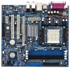
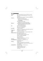
24.4 cm x 22.4 cm CPU: 939-Pin Socket Supporting AMD AthlonTM 64 / 64FX / 64 X2 Processors Supports AMD's Cool 'n' QuietTM Technology (see CAUTION 1) Chipsets: North Bridge: SiS 756 Chipset FSB @ 1 GHz (2.0 GT/s) / 800MHz Supports Untied Overclocking Technology (see CAUTION 2) South Bridge - ASRock 939S56-M | User Manual - Page 7
system. See APPENDIX on page 37 to enable AMD's Cool 'n' QuietTM technology. 2. This motherboard supports Untied Overclocking Technology. FSB enjoys better margin due to fixed PCI/PCIE buses. In other words, CPU FSB is untied during overclocking, but PCIE and PCI buses are in the fixed mode so that - ASRock 939S56-M | User Manual - Page 8
Motherboard Layout 939S56-M FSB 1GHz 12 34 22.4cm (8.8-in) PS2 Mouse 1 PS2_USB_PW1 ATX12V1 56 PARALLEL PORT PS2 Keyboard 7 24.4cm (9.6-in) DDR4 (64/72 bit, 184-pin module) DDR2 (64/72 bit, 184-pin module) DDR3 (64/72 bit, 184-pin module) DDR1 (64/72 bit, 184-pin module) SOCKET 939 - ASRock 939S56-M | User Manual - Page 9
1.4 ASRock 8CH I/O 1 13 12 11 2 3 6 4 7 5 8 10 9 1 Parallel Port 2 RJ-45 Port 3 Rear Speaker (Gray) 4 Side Speaker (Black) 5 Central / Bass (Orange) 6 Line In (Light Blue) * 7 Front Speaker ( - ASRock 939S56-M | User Manual - Page 10
, peripherals, and/or components. 1. Unplug the power cord from the wall socket before touching any component. 2. To avoid damaging the motherboard components due to static electricity, NEVER place your motherboard directly on the carpet or the like. Also remember to use a grounded wrist strap - ASRock 939S56-M | User Manual - Page 11
. Lever 90° Up CPU Golden Triangle Socket Corner STEP 1: Lift Up The Socket Lever STEP 2 / STEP 3: STEP 4: Match The CPU Golden Triangle Push Down And Lock To The Socket Corner The Socket Lever 2.2 Installation of CPU Fan and Heatsink After you install the CPU into this motherboard, it is - ASRock 939S56-M | User Manual - Page 12
of Memory Modules (DIMM) 939S56-M motherboard provides four 184-pin DDR (Double Data Rate) DIMM slots, and supports Dual Channel Memory Technology. (That is, to populate DDR DIMM from the near side of CPU towards to the far side of CPU.) 1. If you want to install two different memory modules, for - ASRock 939S56-M | User Manual - Page 13
matches the break on the slot. notch break notch break The DIMM only fits in one correct orientation. It will cause permanent damage to the motherboard and the DIMM if you force the DIMM into the slot at incorrect orientation. Step 3. Firmly insert the DIMM into the slot until the retaining - ASRock 939S56-M | User Manual - Page 14
) There are 2 PCI slots and 2 PCI Express slots on 939S56-M motherboard. PCI Slots: PCI slots are used to install expansion cards that cards. PCIE2 (PCIE x1 slot) is used for PCI Express cards, such as Gigabit LAN card, SATA II card, etc. Installing an expansion card Step 1. Before installing the - ASRock 939S56-M | User Manual - Page 15
and reset the system parameters to default setup, please turn off the computer and unplug the power cord from the power supply. After waiting for 15 not clear the CMOS right after you update the BIOS. If you need to clear the CMOS when you just finish updating the BIOS, you must boot up the system - ASRock 939S56-M | User Manual - Page 16
one IDE device on this motherboard, please set the IDE device as "Master". Please refer to the instruction of your IDE device vendor for see p.8 No. 12) SATA1 SATA2 These two Serial ATA (SATA) connectors support SATA data cables for internal storage devices. The current SATA interface allows up to - ASRock 939S56-M | User Manual - Page 17
4 ready-to-use USB 2.0 ports on the rear panel. If the rear USB ports are not sufficient, this USB 2.0 header is available to support 2 extra USB 2.0 ports. ASRock 8CH I/OTM provides you 4 ready-to-use USB 2.0 ports on the rear panel. If the rear USB ports are not sufficient, this USB 2.0 header - ASRock 939S56-M | User Manual - Page 18
Please connect a chassis fan cable to this connector and match the black wire to the ground pin. CPU Fan Connector (3-pin CPU_FAN1) (see p.8 No. 30) CPU_FAN_SPEED +12V GND Please connect the CPU fan cable to this connector and match the black wire to the ground pin. ATX Power Connector (20 - ASRock 939S56-M | User Manual - Page 19
" and "non-RAID" mode are options under "SATA Operation Mode" in BIOS setup. Please refer to page 28 for details. They need different drivers during actual operation. 2.8 Hot Plug Function for SATA HDDs 939S56-M motherboard supports Hot Plug function for SATA devices. What is Hot Plug Function? If - ASRock 939S56-M | User Manual - Page 20
Operation in "RAID" Mode If you want to install Windows 2000, Windows XP, or Windows XP 64-bit OS on your SATA HDDs with RAID functions, you will need to make a SATA driver before you start the OS installation. STEP 1: Insert the ASRock Support CD into your optical drive to boot your system. (Do - ASRock 939S56-M | User Manual - Page 21
BIOS SETUP UTILITY to configure your system. The Flash Memory on the motherboard stores the BIOS SETUP UTILITY. You may run the BIOS SETUP UTILITY when you start up the computer then back on. Because the BIOS software is constantly being updated, the following BIOS setup screens and descriptions are - ASRock 939S56-M | User Manual - Page 22
H/W Monitor Boot Security Exit System Overview System Time System Date [17:00:09] [Tue 04/26/2005] BIOS Version : 939S56-M BIOS P1.0 Processor Type : AMD Athlon(tm) 64 Processor 3400+ Processor Speed : 2200 MHz Microcode Update : F7A/3A L1 Cache Size : 128KB L2 Cache Size : 1024KB Total - ASRock 939S56-M | User Manual - Page 23
to malfunction. 3.3.1 CPU Configuration BIOS SETUP UTILITY Advanced CPU Configuration Overclock Mode CPU Frequency (MHz) PCIE ] If AUTO, multiplier and voltage will be left at the rated frequency/voltage. If Manual, multiplier and voltage will be set based on User Selection in Setup. +F1 F9 - ASRock 939S56-M | User Manual - Page 24
[Auto] by default. If it is set to [Manual], you may adjust the value of Processor Multiplier and Processor Voltage. However, it is recommended to keep the default value for system stability. BIOS SETUP UTILITY Advanced CPU Configuration Overclock Mode CPU Frequency (MHz) PCIE Frequency (MHz) Boot - ASRock 939S56-M | User Manual - Page 25
Processor Voltage This item will show when "Multiplier/Voltage Change" is set to [Manual]; otherwise, it will be hidden. You may set the value from [1.550V] the value of this item. Memory Clock This item can be set by the code using [Auto]. You can set one of the standard values as listed: [133 - ASRock 939S56-M | User Manual - Page 26
the onboard AC97 Audio feature. OnBoard LAN This allows you to enable or disable the onboard LAN feature. Primary Graphics Adapter This item The default value is [Auto]. 3.3.3 ACPI Configuration Advanced BIOS SETUP UTILITY ACPI Settings Suspend To RAM Repost Video on STR Resume Restore on AC / - ASRock 939S56-M | User Manual - Page 27
supports it. If you set this item to [Disabled], the function "Repost Video on STR Resume" will be hidden. Repost Video on STR Resume This feature allows you to repost video on STR resume. It is recommended to enable this feature under Microsoft Windows 98 / ME. (STR refers to suspend to RAM BIOS - ASRock 939S56-M | User Manual - Page 28
[non-RAID]. However, if you want to install Windows 98 SE / ME without RAID functions, please still Primary IDE Master" as the example in the following instruction, which can be applied to the configurations of "Primary motherboard, the IDE Configuration screen will be as below. Advanced BIOS - ASRock 939S56-M | User Manual - Page 29
BIOS SETUP UTILITY Advanced Primary IDE Master Device Vendor Size LBA Mode Block Mode PIO Mode Async DMA Ultra DMA S.M.A.R.T. :Hard Disk :MAXTOR 6L080J4 :80.0 GB :Supported :16Sectors :4 :MultiWord DMA-2 :Ultra DMA-6 :Supported disk > 512 MB under DOS and Windows; for Netware and UNIX user, select - ASRock 939S56-M | User Manual - Page 30
32-Bit Data Transfer Use this item to enable 32-bit access to maximize the IDE hard disk data transfer rate. 3.3.5 PCIPnP Configuration Advanced BIOS SETUP UTILITY Advanced PCI / PnP Settings WARNING: Setting wrong values in below sections may cause system to malfunction. Value in units of PCI - ASRock 939S56-M | User Manual - Page 31
Channel Parallel Port IRQ OnBoard Game Port OnBoard MIDI Port [Enabled] [3F8 / IRQ4] [Disabled] [378] [ECP + EPP] [1.9] [DMA3] [IRQ7] [Enabled] [Disabled] Allow BIOS to Enable or Disable Floppy Controller. +F1 F9 F10 ESC Select Screen Select Item Change Option General Help Load Defaults Save and - ASRock 939S56-M | User Manual - Page 32
the MIDI Port or disable it. Configuration options: [Disabled], [300], and [330]. 3.3.8 USB Configuration BIOS SETUP UTILITY Advanced USB Configuration USB Controller USB 2.0 Support Legacy USB Support [Enabled] [Enabled] [Disabled] To enable or disable the onboard USB controllers. +F1 F9 F10 - ASRock 939S56-M | User Manual - Page 33
you to monitor the status of the hardware on your system, including the parameters of the CPU temperature, motherboard temperature, CPU fan speed, chassis fan speed, and the critical voltage. BIOS SETUP UTILITY Main Advanced H/W Monitor Boot Security Exit Hardware Health Event Monitoring - ASRock 939S56-M | User Manual - Page 34
may set or change the supervisor/user password for the system. For the user password, you may also clear it. Main Advanced BIOS SETUP UTILITY H/W Monitor Boot Security Settings Supervisor Password : Not Installed User Password : Not Installed Change Supervisor Password Change User Password - ASRock 939S56-M | User Manual - Page 35
and exit setup?" Select [OK] to save the changes and exit the BIOS SETUP UTILITY. Discard Changes and Exit When you select this option, it message, "Discard changes and exit setup?" Select [OK] to exit the BIOS SETUP UTILITY without saving any changes. Discard Changes When you select this option - ASRock 939S56-M | User Manual - Page 36
available devices drivers including ASRock Express GbL PCI Express LAN card driver if the system detects the installed devices. Please install the necessary drivers to activate the devices. 4.2.3 Utilities Menu The Utilities Menu shows the applications software that the motherboard supports. Click - ASRock 939S56-M | User Manual - Page 37
feature, please make sure to install "AMD Processor Driver" from the "Support CD" first. If you are using Windows 2000/XP operating system, please follow the instruction below to enable AMD's Cool 'n' QuietTM technology: 1. From the Windows 2000/XP operating system, click the Start button. Select
-
 1
1 -
 2
2 -
 3
3 -
 4
4 -
 5
5 -
 6
6 -
 7
7 -
8
-
9
-
10
-
11
-
12
-
13
-
14
-
15
-
16
-
17
-
18
-
19
-
20
-
21
-
22
-
23
-
24
-
25
-
26
-
27
-
28
-
29
-
30
-
31
-
32
-
33
-
34
-
35
-
36
-
37
 |
 |

1
939S56-M
User Manual
Version 1.0
Published May 2005
Copyright©2005 ASRock INC. All rights reserved.