ASRock 945GCM-S User Manual
ASRock 945GCM-S Manual
 |
View all ASRock 945GCM-S manuals
Add to My Manuals
Save this manual to your list of manuals |
ASRock 945GCM-S manual content summary:
- ASRock 945GCM-S | User Manual - Page 1
945GCM-S User Manual Version 1.0 Published August 2008 Copyright©2008 ASRock INC. All rights reserved. 1 - ASRock 945GCM-S | User Manual - Page 2
without written consent of ASRock Inc. Products and corporate names appearing in this manual may or may not be intent to infringe. Disclaimer: Specifications and information contained in this manual are furnished for informational use battery adopted on this motherboard contains Perchlorate, a toxic - ASRock 945GCM-S | User Manual - Page 3
Slots (PCI and PCI Express Slots 17 2.7 Jumpers Setup 18 2.8 Onboard Headers and Connectors 19 2.9 SATAII Hard Disk Setup Guide 23 2.10 Serial ATA (SATA) / Serial ATAII (SATAII) Hard Disks Installation 24 2.11 Driver Installation Guide 24 2.12 Untied Overclocking Technology 24 3 BIOS SETUP - ASRock 945GCM-S | User Manual - Page 4
4 Software Support 43 4.1 Install Operating System 43 4.2 Support CD Information 43 4.2.1 Running Support CD 43 4.2.2 Drivers Menu 43 4.2.3 Utilities Menu 43 4.2.4 Contact Information 43 4 - ASRock 945GCM-S | User Manual - Page 5
of this manual occur, the updated version will be available on ASRock website without further notice. You may find the latest VGA cards and CPU support lists on ASRock website as well. ASRock website http://www.asrock.com If you require technical support related to this motherboard, please visit - ASRock 945GCM-S | User Manual - Page 6
Platform CPU Chipset Memory Expansion Slot Graphics Audio LAN Rear Panel I/O Connector - Micro ATX Form Factor: 9.6-in x 7.5-in, 24.4 cm x 19.1 cm - LGA 775 for Intel® Dual Core CoreTM 2 Extreme / CoreTM 2 Duo / Pentium® Dual Core / Celeron®, supporting Dual Core Wolfdale processors - Compatible - ASRock 945GCM-S | User Manual - Page 7
- AMBIOS 2.3.1 Support - Supports Smart BIOS Support CD - Drivers, Utilities, AntiVirus Software (Trial Version) Unique Feature - Intelligent Energy Saver (see CAUTION 10) - Hybrid Booster: - CPU Frequency Stepless Control (see CAUTION 11) - ASRock U-COP (see CAUTION 12) - Boot Failure Guard - ASRock 945GCM-S | User Manual - Page 8
below for the CPU FSB frequency and its corre- sponding memory support frequency. CPU FSB Frequency Memory Support Frequency 1333 DDR2 533*, DDR2 667 1066 DDR2 533, DDR2 667 800 DDR2 400, DDR2 533, DDR2 667 533 DDR2 400, DDR2 533 * When you use a FSB1333-CPU on this motherboard, it will - ASRock 945GCM-S | User Manual - Page 9
automatically shutdown. Before you resume the system, please check if the CPU fan on the motherboard functions properly and unplug the power cord, then plug it back again. To improve heat dissipation, remember to spray thermal grease between the CPU and the heatsink when you install the PC system. 9 - ASRock 945GCM-S | User Manual - Page 10
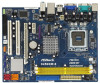
Top: RJ-45 LAN PHY Super IO CD1 AUDIO CODEC HD_AUDIO1 FLOPPY1 1 OC 800 1 LPT1 1 PCIE1 Intel 945GC Chipset CMOS Battery CLRCMOS1 PCIE2 PCI EXPRESS PCI1 IDE1 RoHS Intel ICH7 SATAII_3 SATAII_1 PCI2 CHA_FAN1 4Mb BIOS PANEL 1 PLED PWRBTN 1 HDLED RESET USB4_5 1 USB6_7 1 SPEAKER1 1 945GCM - ASRock 945GCM-S | User Manual - Page 11
(Pink) 7 USB 2.0 Ports (USB01) 8 VGA Port 9 COM Port 10 PS/2 Keyboard Port (Purple) * To enable Multi-Streaming function, you need to connect a front panel audio cable to the front panel audio header. Please refer to below steps for the software setting of Multi-Streaming. For Windows® XP: After - ASRock 945GCM-S | User Manual - Page 12
945GCM-S is a Micro ATX form factor (9.6" x 7.5", 24.4 x 19.1 cm) motherboard. Before you install the motherboard, study the configuration of your chassis to ensure that the motherboard fits into it. Make sure to unplug the power cord before installing or removing the motherboard. Failure - ASRock 945GCM-S | User Manual - Page 13
plate to fully open position at approximately 100 degrees. Step 2. Insert the 775-LAND CPU: Step 2-1. Hold the CPU by the edges where are marked with black lines. black line black line Step 2-2. Orient the CPU with IHS (Integrated Heat Sink) up. Locate Pin1 and the two orientation key notches - ASRock 945GCM-S | User Manual - Page 14
CPU is within the socket and properly mated to the orient keys. Step 3. Remove PnP Cap (Pick and Place Cap): Use your left hand index finger and thumb to support PnP cap. 2. This cap must be placed if returning the motherboard for after service. Step 4. Close the socket: Step 4-1. Rotate the load - ASRock 945GCM-S | User Manual - Page 15
are securely fastened and in good contact with each other. Then connect the CPU fan to the CPU_FAN connector (CPU_FAN1, see page 10, No. 4). For proper installation, please kindly refer to the instruction manuals of your CPU fan and heatsink. Below is an example to illustrate the installation of the - ASRock 945GCM-S | User Manual - Page 16
2.5 Installation of Memory Modules (DIMM) 945GCM-S motherboard provides two 240-pin DDR2 (Double Data Rate 2) DIMM slots, and supports Dual Channel Memory Technology. For dual channel configuration, you always need to install two identical (the same brand, speed, size and chip-type) memory modules - ASRock 945GCM-S | User Manual - Page 17
slots: PCIE1 (PCIE x1 slot) is used for PCI Express cards with x1 lane width cards, such as Gigabit LAN card, SATA2 card, etc. PCIE2 (PCIE x16 slot) is used for PCI Express cards with x16 lane width graphics cards. If you install the add-on PCI Express VGA card to PCIE2 (PCIE x16 slot), the onboard - ASRock 945GCM-S | User Manual - Page 18
pin2, pin3 to enable +5VSB (standby) for PS/2 +5V +5VSB or USB wake up events. Note: To select +5VSB, it requires 2 Amp and Default Note: If you want to overclock the FSB800-CPU (e.g. Cel400, E1000, E2000, E4000, E5000, E6000 series CPU) to FSB1066 on this motherboard, you need to adjust the - ASRock 945GCM-S | User Manual - Page 19
, see p.10 No. 7) PIN1 IDE1 connect the blue end connect the black end to the motherboard to the IDE devices 80-conductor ATA 66/100 cable Note: Please refer to the instruction of your IDE device vendor for the details. SATAII_1 SATAII_3 SATAII_2 SATAII_4 Serial ATAII Connectors (SATAII_1 - ASRock 945GCM-S | User Manual - Page 20
cable that allows convenient connection and control of audio devices. 1. High Definition Audio supports Jack Sensing, but the panel wire on the chassis must support HDA to function correctly. Please follow the instruction in our manual and chassis manual to install your system. 2. If you use AC - ASRock 945GCM-S | User Manual - Page 21
E. Enter BIOS Setup Utility. Enter Advanced Settings, and then select Chipset Configuration. Set the Front Panel Control option from [Auto] to [Enabled]. F. Enter Windows system. Click the icon on the lower right hand taskbar to enter Realtek HD Audio Manager. For Windows® 2000 / XP / XP 64-bit - ASRock 945GCM-S | User Manual - Page 22
Though this motherboard provides 4-Pin CPU fan (Quiet Fan) support, the 3-Pin CPU fan still can work successfully even without the fan speed control function. If you plan to connect the 3-Pin CPU fan to the CPU fan connector on this motherboard, please connect it to Pin 1-3. Pin 1-3 Connected 3-Pin - ASRock 945GCM-S | User Manual - Page 23
guide. Some default setting of SATAII hard disks may not be at SATAII mode, which operate with the best performance. In order to enable SATAII function, please follow the below instruction website for details: http://www.hitachigst.com/hdd/support/download.htm The above examples are just for your - ASRock 945GCM-S | User Manual - Page 24
drivers compatible to your system can be auto-detected and listed on the support CD driver page. Please follow the order from up to bottom side to install those required drivers. Therefore, the drivers you install can work properly. 2 . 1 2 Untied Overclocking Technology This motherboard supports - ASRock 945GCM-S | User Manual - Page 25
system off and then back on. Because the BIOS software is constantly being updated, the following BIOS setup screens and descriptions are for reference purpose information Advanced To set up the advanced BIOS features PCIPnP To set up the PCI features Boot To set up the default system device to - ASRock 945GCM-S | User Manual - Page 26
UTILITY Main Smart Advanced H/W Monitor Boot Security Exit System Overview System Time System Date [14:00:09] [Thu 07/31/2008] BIOS Version : 945GCM-S P1.00 Processor Type : Intel (R) CPU 3.40 GHz (64bit) Processor Speed : 3400 MHz Microcode Update : F34/17 Cache Size : 1024KB Total - ASRock 945GCM-S | User Manual - Page 27
SETUP UTILITY. Load BIOS Defaults Load BIOS default values for all the setup questions. F9 key can be used for this operation. Load Performance Setup Default (IDE/SATA) This performance setup default may not be compatible with all system configurations. If system boot failure occurs after loading - ASRock 945GCM-S | User Manual - Page 28
, Inc. Setting wrong values in this section may cause the system to malfunction. 3.4.1 CPU Configuration BIOS SETUP UTILITY Advanced CPU Configuration Overclock Mode CPU Frequency (MHz) PCIE Frequency (MHz) Boot Failure Guard Spread Spectrum Ratio Actual Value Enhance Halt State Max CPUID Value - ASRock 945GCM-S | User Manual - Page 29
you changing the ratio value of this motherboard. If the CPU you adopt supports EIST (Intel (R) SpeedStep(tm) tech.), and you plan to adjust the ratio value, please disable the option " Intel (R) SpeedStep(tm) tech." in advance. Enhance Halt State All processors support the Halt State (C1). The C1 - ASRock 945GCM-S | User Manual - Page 30
] if using Microsoft® Windows® XP, or Linux kernel version 2.4.18 or higher. This option will be hidden if the installed CPU does not support Hyper-Threading technology. Intel (R) SpeedStep(tm) tech. Intel (R) SpeedStep(tm) tech. is Intel's new power saving technology. Processor can switch between - ASRock 945GCM-S | User Manual - Page 31
DVMT (Dynamic Video Memory Technology) is an architecture that offers breakthrough performance for the motherboard through efficient memory utilization. In Fixed mode, a fixed-size fragment of the system memory is allocated to the graphics core. In DVMT mode, the graphics driver allocates memory as - ASRock 945GCM-S | User Manual - Page 32
If you select [Auto], the onboard HD Audio will be disabled when PCI Sound Card is plugged. Front Panel Select [Auto], [Enabled] or [Disabled] for the onboard HD Audio Front Panel. OnBoard Lan This allows you to enable or disable the "OnBoard Lan" feature. PCI Fix Function This allows you to enable - ASRock 945GCM-S | User Manual - Page 33
3.4.3 ACPI Configuration BIOS SETUP UTILITY Advanced ACPI Configuration Suspend To RAM Restore on AC/Power Loss Ring-In Power On PCI Devices Power On PS / 2 Keyboard Power On RTC Alarm Power On ACPI HPET Table [Disabled] [Power Off] [Disabled] [Disabled] [Disabled] [Disabled] [Disabled] Select - ASRock 945GCM-S | User Manual - Page 34
Compatible] when you install legacy OS (Windows NT). If native OS (Windows 2000 / XP) is installed, please select [Enhanced]. When [Compatible not work. Because Intel® ICH7 south bridge only supports four IDE devices under legacy OS (Windows NT), you have to choose [SATA 1, SATA instruction. 34 - ASRock 945GCM-S | User Manual - Page 35
BIOS SETUP UTILITY Advanced Primary IDE Master Device Vendor Size LBA Mode Block Mode PIO Mode Async DMA Ultra DMA S.M.A.R.T. Type LBA/Large Mode Block (Multi-Sector Transfer) PIO Mode DMA Mode S.M.A.R.T. 32Bit Data Transfer :Hard Disk :ST340014A :40.0 GB :Supported DOS and Windows; for Netware - ASRock 945GCM-S | User Manual - Page 36
and Exit Exit v02.54 (C) Copyright 1985-2005, American Megatrends, Inc. PCI Latency Timer The default value is 32. It is recommended to keep the default value unless the installed PCI expansion cards' specifications require other settings. PCI IDE BusMaster Use this item to enable or disable the - ASRock 945GCM-S | User Manual - Page 37
Port Address Parallel Port Mode EPP Version ECP Mode DMA Channel Parallel Port IRQ [Enabled] [3F8 / IRQ4] [378] [ECP + EPP] [1.9] [DMA3] [IRQ7] Allow BIOS to Enable or Disable Floppy Controller. +F1 F9 F10 ESC Select Screen Select Item Change Option General Help Load Defaults Save and Exit Exit - ASRock 945GCM-S | User Manual - Page 38
parallel port. Configuration options: [IRQ5] and [IRQ7]. 3.4.8 USB Configuration BIOS SETUP UTILITY Advanced USB Configuration USB Controller USB 2.0 Support Legacy USB Support [Enabled] [Enabled] [BIOS Setup Only] To enable or disable the onboard USB controllers. +F1 F9 F10 ESC Select Screen - ASRock 945GCM-S | User Manual - Page 39
Only] - USB devices are allowed to use only under BIOS setup and Windows / Linux OS. 3.5 Hardware Health Event Monitoring Screen In this section, it allows you to monitor the status of the hardware on your system, including the parameters of the CPU temperature, motherboard temperature, CPU fan - ASRock 945GCM-S | User Manual - Page 40
Exit ESC Exit v02.54 (C) Copyright 1985-2005, American Megatrends, Inc. 3.6.1 Boot Settings Configuration BIOS SETUP UTILITY Boot Boot Settings Configuration Full Screen Logo AddOn ROM Display Boot From Onboard LAN Bootup Num-Lock [Enabled] [Enabled] [Disabled] [On] Disabled: Displays normal - ASRock 945GCM-S | User Manual - Page 41
Onboard LAN feature. Boot Up Num-Lock If this item is set to [On], it will automatically activate the Numeric Lock function after boot-up. 3.7 Security Screen In this section, you may set or change the supervisor/user password for the system. For the user password, you may also clear it. BIOS SETUP - ASRock 945GCM-S | User Manual - Page 42
3.8 Exit Screen BIOS SETUP UTILITY Main Smart Advanced H/W Monitor Boot Security Exit Exit Options Save Changes and "Save configuration changes and exit setup?" Select [OK] to save the changes and exit the BIOS SETUP UTILITY. Discard Changes and Exit When you select this option, it will pop-out the - ASRock 945GCM-S | User Manual - Page 43
install the necessary drivers to activate the devices. 4.2.3 Utilities Menu The Utilities Menu shows the applications software that the motherboard supports. Click on a specific item then follow the installation wizard to install it. 4.2.4 Contact Information If you need to contact ASRock or want to
-
 1
1 -
 2
2 -
 3
3 -
 4
4 -
 5
5 -
 6
6 -
 7
7 -
8
-
9
-
10
-
11
-
12
-
13
-
14
-
15
-
16
-
17
-
18
-
19
-
20
-
21
-
22
-
23
-
24
-
25
-
26
-
27
-
28
-
29
-
30
-
31
-
32
-
33
-
34
-
35
-
36
-
37
-
38
-
39
-
40
-
41
-
42
-
43
 |
 |

1
945GCM-S
User Manual
Version 1.0
Published August 2008
Copyright©2008 ASRock INC. All rights reserved.