ASRock 970 Extreme3 R2.0 User Manual
ASRock 970 Extreme3 R2.0 Manual
 |
View all ASRock 970 Extreme3 R2.0 manuals
Add to My Manuals
Save this manual to your list of manuals |
ASRock 970 Extreme3 R2.0 manual content summary:
- ASRock 970 Extreme3 R2.0 | User Manual - Page 1
970 Extreme3 R2.0 User Manual Version 1.0 Published October 2012 Copyright©2012 ASRock INC. All rights reserved. 1 - ASRock 970 Extreme3 R2.0 | User Manual - Page 2
purchaser for backup purpose, without written consent of ASRock Inc. Products and corporate names appearing in this manual may or may not be registered trademarks or copyrights USA ONLY The Lithium battery adopted on this motherboard contains Perchlorate, a toxic substance controlled in Perchlorate - ASRock 970 Extreme3 R2.0 | User Manual - Page 3
2.2 Installation of CPU Fan and Heatsink 18 2.3 Installation of Memory Modules (DIMM 19 2.4 Expansion Slots (PCI and PCI Express Slots 21 2.5 CrossFireXTM and Quad CrossFireXTM Operation Guide 22 2.6 Surround Display Information 25 2.7 ASRock Smart Remote Installation Guide 26 2.8 Jumpers - ASRock 970 Extreme3 R2.0 | User Manual - Page 4
UEFI Menu Bar 41 3.1.2 Navigation Keys 42 3.2 Main Screen 43 3.3 OC Tweaker Screen 44 3.4 Advanced Screen 48 3.4.1 CPU 62 4. Software Support 63 4.1 Install Operating System 63 4.2 Support CD Information 63 4.2.1 Running Support CD 63 4.2.2 Drivers Menu 63 4.2.3 Utilities - ASRock 970 Extreme3 R2.0 | User Manual - Page 5
information about the model you are using. www.asrock.com/support/index.asp 1.1 Package Contents ASRock 970 Extreme3 R2.0 Motherboard (ATX Form Factor) ASRock 970 Extreme3 R2.0 Quick Installation Guide ASRock 970 Extreme3 R2.0 Support CD 2 x Serial ATA (SATA) Data Cables (Optional) 1 x I/O Panel - ASRock 970 Extreme3 R2.0 | User Manual - Page 6
Specifications Platform CPU Chipset Memory Expansion Slot Audio LAN - ATX Form Factor - ASRock DuraCap (2.5 x longer life time) (100% Japan-made high-quality Conductive Polymer Capacitors) - Support for Socket AM3+ processors - Support for Socket AM3 processors: AMD PhenomTM II X6 / X4 / X3 / X2 - ASRock 970 Extreme3 R2.0 | User Manual - Page 7
audio connector - 3 x USB 2.0 headers (support 6 USB 2.0 ports) - 1 x USB 3.0 header (supports 2 USB 3.0 ports) - 32Mb AMI UEFI Legal BIOS with GUI support - Supports "Plug and Play" - ACPI 1.1 Compliance Wake Up Events - Supports jumperfree - SMBIOS 2.3.1 Support - CPU, VCCM, NB, SB Voltage Multi - ASRock 970 Extreme3 R2.0 | User Manual - Page 8
visit our website: http://www.asrock.com WARNING Please realize that there is a certain risk involved with overclocking, including adjusting the setting in the BIOS, applying Untied Overclocking Technology, or using third-party overclocking tools. Overclocking may affect your system's stability - ASRock 970 Extreme3 R2.0 | User Manual - Page 9
speed is supported depends on the AM3/AM3+ CPU you adopt. If you want to adopt DDR3 2100/1866/1800/1600 memory module on this motherboard, please refer to the memory support list on our website for the compatible memory modules. Non OC mode's DDR3 1866 is supported by AM3+ CPU. ASRock website: http - ASRock 970 Extreme3 R2.0 | User Manual - Page 10
1.3 Unique Features ASRock Extreme Tuning Utility (AXTU) ASRock Extreme Tuning Utility (AXTU) is an all-in-one tool to ne-tune different system functions in a user-friendly interface, which includes Hardware Monitor, Fan Control, Overclocking, OC DNA, IES and XFast RAM. In Hardware Monitor, it shows - ASRock 970 Extreme3 R2.0 | User Manual - Page 11
data streams you are transferring currently. ASRock XFast RAM ASRock XFast RAM is a new function that is included into ASRock Extreme Tuning Utility (AXTU). It fully utilizes the memory space that cannot be used under Windows® OS 32-bit CPU. ASRock XFast RAM shortens the loading time of previously - ASRock 970 Extreme3 R2.0 | User Manual - Page 12
loss occurs during the BIOS update process, ASRock Crashless BIOS will automatically finish the BIOS update procedure after regaining power. Please note that BIOS files need to be placed in the root directory of your USB disk. Only USB2.0 ports support this feature. ASRock OMG (Online Management - ASRock 970 Extreme3 R2.0 | User Manual - Page 13
to get up to 15.77% performance boost! With the smart X-Boost, overclocking CPU can become a near one-button process. * The functionality of "Unlock CPU Cores" feature might vary by different processors. ASRock Restart to UEFI Windows® 8 brings the ultimate boot up experience. The lightning boot up - ASRock 970 Extreme3 R2.0 | User Manual - Page 14
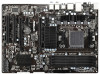
RJ-45 LAN USB 2.0 T: USB2 B: USB3 eSATA3 USB 3.0 T: USB0 B: USB1 CHA_FAN3 SOCKET AM3b CPU_FAN2 CPU_FAN1 Front USB 3.0 USB3_2_3 AMD 970 PCIE1 Chipset PCIE2 AM3+ 140W CPU DDR3 2100+ Support 8-Core CPU DDR3_A1 (64 bit, 240-FpinSBmo8d0ul0e) DDR3_A2 (64 bit, 240-pin module) DDR3_B1 (64 - ASRock 970 Extreme3 R2.0 | User Manual - Page 15
1.4 I/O Panel 1 2 3 4 7 5 8 6 9 15 14 13 1 PS/2 Mouse Port (Green) * 2 LAN RJ-45 Port 3 USB 2.0 Ports (USB23) 4 Side Speaker (Gray) 5 Rear Speaker (Black) 6 Central / Bass (Orange) 7 Line In (Light Blue) ** 8 Front Speaker (Lime) 12 11 10 9 10 *** 11 12 13 14 15 Microphone (Pink) USB - ASRock 970 Extreme3 R2.0 | User Manual - Page 16
Primary output" to use Rear Speaker, Central/Bass, and Front Speaker, or select "Realtek HDA Audio 2nd output" to use front panel audio. *** eSATA3 connector supports SATA Gen3 in cable 1M. 16 - ASRock 970 Extreme3 R2.0 | User Manual - Page 17
, peripherals, and/or components. 1. Unplug the power cord from the wall socket before touching any component. 2. To avoid damaging the motherboard components due to static electricity, NEVER place your motherboard directly on the carpet or the like. Also remember to use a grounded wrist strap - ASRock 970 Extreme3 R2.0 | User Manual - Page 18
Corner Small Triangle STEP 2 / STEP 3: STEP 4: Match The CPU Golden Triangle Push Down And Lock To The Socket Corner Small The Socket Lever Triangle 2.2 Installation of CPU Fan and Heatsink After you install the CPU into this motherboard, it is necessary to install a larger heatsink and - ASRock 970 Extreme3 R2.0 | User Manual - Page 19
2.3 Installation of Memory Modules (DIMM) This motherboard provides four 240-pin DDR3 (Double Data Rate 3) DIMM slots, and supports Dual Channel Memory Technology. For dual channel configuration, you always need to install identical (the same brand, speed, size and chip-type) DDR3 DIMM pair in the - ASRock 970 Extreme3 R2.0 | User Manual - Page 20
matches the break on the slot. notch break notch break The DIMM only fits in one correct orientation. It will cause permanent damage to the motherboard and the DIMM if you force the DIMM into the slot at incorrect orientation. Step 3. Firmly insert the DIMM into the slot until the retaining - ASRock 970 Extreme3 R2.0 | User Manual - Page 21
support CrossFireXTM function. PCIE4 (PCIE x16 slot) is used for PCI Express x4 lane width cards, or used to install PCI Express graphics cards to support bandwidth while PCIE4 slot will work at x4 bandwidth. 3. Please connect a chassis fan to motherboard chassis fan connector (CHA_FAN1, CHA_FAN2 or - ASRock 970 Extreme3 R2.0 | User Manual - Page 22
3D application. Currently CrossFireXTM feature is supported with Windows® XP with Service Pack 2 / VistaTM / 7 / 8 OS. Quad CrossFireXTM feature is supported with Windows® VistaTM / 7 / 8 OS only. Please check AMD website for AMD CrossFireXTM driver updates. 1. If a customer incorrectly configures - ASRock 970 Extreme3 R2.0 | User Manual - Page 23
Bridge Interconnects on the top of the Radeon graphics cards. (The CrossFire Bridge is provided with the graphics card you purchase, not bundled with this motherboard. Please refer to your graphics card vendor for details.) CrossFire Bridge or Step 3. Connect the DVI monitor cable to the DVI - ASRock 970 Extreme3 R2.0 | User Manual - Page 24
to uninstall any previously installed Catalyst drivers prior to installation. Please check AMD website for AMD driver updates. Step 3. Step 4. Step 5. Install the required drivers to your system. For Windows® XP OS: A. AMD recommends Windows® XP Service Pack 2 or higher to be installed - ASRock 970 Extreme3 R2.0 | User Manual - Page 25
technology, please check AMD website for updates and details. 2.6 Surround Display Feature This motherboard supports Surround Display upgrade. With the external add-on PCI Express VGA cards, you can easily enjoy the benefits of Surround Display feature. For the detailed instruction, please refer to - ASRock 970 Extreme3 R2.0 | User Manual - Page 26
2.7 ASRock Smart Remote Installation Guide ASRock Smart Remote is only used for ASRock motherboard with CIR header. Please refer to below procedures for the quick installation and usage of ASRock Smart Remote. Step1. Find the CIR header located next to the USB 2.0 header on ASRock motherboard. - ASRock 970 Extreme3 R2.0 | User Manual - Page 27
chassis on the market. 3. The Multi-Angle CIR Receiver does not support Hot-Plug function. Please install it before you boot the system. * ASRock Smart Remote is only supported by some of ASRock motherboards. Please refer to ASRock website for the motherboard support list: http://www.asrock.com 27 - ASRock 970 Extreme3 R2.0 | User Manual - Page 28
need to clear the CMOS when you just finish updating the BIOS, you must boot up the system first, and then shut it down before you do the clear-CMOS ac- tion. Please be noted that the password, date, time, user default profile, 1394 GUID and MAC address will be cleared only if - ASRock 970 Extreme3 R2.0 | User Manual - Page 29
1 GND P+8 P-8 USB_PWR IRTX +5VSB DUMMY 1 GND IRRX Besides four default USB 2.0 ports on the I/O panel, there are three USB 2.0 headers on this motherboard. Each USB 2.0 header can support two USB 2.0 ports. This header supports an optional wireless transmitting and receiving infrared module. 29 - ASRock 970 Extreme3 R2.0 | User Manual - Page 30
allows convenient connection and control of audio devices. 1. High Definition Audio supports Jack Sensing, but the panel wire on the chassis must support HDA to function correctly. Please follow the instruction in our manual and chassis manual to install your system. 2. If you use AC'97 audio - ASRock 970 Extreme3 R2.0 | User Manual - Page 31
). Please connect the fan cables to the fan connectors and match the black wire to the ground pin. CHA_FAN1/2/3 fan speed can be controlled through UEFI or AXTU. (3-pin CHA_FAN3) (see p.14 No. 2) (3-pin PWR_FAN1) (see p.14 No. 10) GND +12V PWR_FAN_SPEED 31 - ASRock 970 Extreme3 R2.0 | User Manual - Page 32
(4-pin CPU_FAN1) +12V (see p.14 No. 6) GND 1 2 3 4 Please connect the CPU fan cable to the connector and match the black wire to the ground pin. Though this motherboard provides 4-Pin CPU fan (Quiet Fan) support, the 3-Pin CPU fan still can work successfully even without the fan speed - ASRock 970 Extreme3 R2.0 | User Manual - Page 33
IntA_P2_SSTXIntA_P2_SSTX+ GND IntA_P2_DIntA_P2_D+ Vbus IntA_P3_SSRXIntA_P3_SSRX+ GND IntA_P3_SSTXIntA_P3_SSTX+ GND IntA_P3_DIntA_P3_D+ DUMMY Besides two default USB 3.0 ports on the I/O panel, there is one USB 3.0 header on this motherboard. This USB 3.0 header can support two USB 3.0 ports. 33 - ASRock 970 Extreme3 R2.0 | User Manual - Page 34
SATA3) Hard Disks Installation This motherboard adopts AMD SB950 chipset that supports Serial ATA3 (SATA3) hard disks and RAID (RAID 0, RAID 1, RAID 5 and RAID 10) functions. You may install SATA3 hard disks on this motherboard for internal storage devices. This section will guide you to install the - ASRock 970 Extreme3 R2.0 | User Manual - Page 35
is installed into system properly. The latest SATA3 driver is available on our support website: www.asrock.com 4. Make sure to use the SATA power cable & data cable, which are from our motherboard package. 5. Please follow below instructions step by step to reduce the risk of HDD crash or data - ASRock 970 Extreme3 R2.0 | User Manual - Page 36
the power supply 1x4-pin cable. Connect SATA data cable to the motherboard's SATAII / SATA3 connector. SATA power cable 1x4-pin power connector attention, before you process the Hot Unplug: Please do follow below instruction sequence to process the Hot Unplug, improper procedure will cause the - ASRock 970 Extreme3 R2.0 | User Manual - Page 37
follow below steps. STEP 1: Set up UEFI. A. Enter UEFI SETUP UTILITY Advanced screen Storage Configuration. B. Set the "SATA Mode" option to [RAID]. STEP 2: Make a SATA3 Driver Diskette. (Please use an USB floppy or a floppy disk.) A. Insert the ASRock Support CD into your optical drive to - ASRock 970 Extreme3 R2.0 | User Manual - Page 38
you need to check the RAID installation guide in the Support CD for proper configuration. Please refer to the BIOS RAID installation guide part of the document in the following path in the Support CD: .. \ RAID Installation Guide STEP 3: Make a SATA3 Driver Diskette. (Please use an USB floppy or - ASRock 970 Extreme3 R2.0 | User Manual - Page 39
insert the SATA3 driver diskette containing the AMD AHCI driver. After reading the floppy disk, the driver will be presented. Select the driver to install according to the OS you install. Using SATA3 HDDs without NCQ and Hot Plug functions (IDE mode) STEP 1: Set up UEFI. A. Enter UEFI SETUP UTILITY - ASRock 970 Extreme3 R2.0 | User Manual - Page 40
Technology This motherboard supports Untied Overclocking Technology, which means during overclocking, FSB enjoys better margin due to fixed PCI / PCIE buses. Before you enable Untied Overclocking function, please enter "Overclock Mode" option of UEFI setup to set the selection from [Auto] to [Manual - ASRock 970 Extreme3 R2.0 | User Manual - Page 41
Memory on the motherboard stores the UEFI SETUP UTILITY. You may run the UEFI SETUP UTILITY when you start up the computer. Please press or during the Power-On-Self-Test (POST) to enter the UEFI SETUP UTILITY, otherwise, POST up overclocking features Advanced To set up the advanced UEFI - ASRock 970 Extreme3 R2.0 | User Manual - Page 42
of the screen To display the General Help Screen Discard changes and exit the UEFI SETUP UTILITY Load optimal default values for all the settings Save changes and exit the UEFI SETUP UTILITY Print screen Jump to the Exit Screen or exit the current screen - ASRock 970 Extreme3 R2.0 | User Manual - Page 43
screen will appear and display the system overview. System Browser System Browser can let you easily check your current system configuration in UEFI setup. OMG (Online Management Guard) Administrators are able to establish an internet curfew or restrict internet access at specified times via OMG - ASRock 970 Extreme3 R2.0 | User Manual - Page 44
Overclock Mode. Configuration options: [Auto] and [Manual]. The default value is [Auto]. Spread Spectrum This item should always be [Auto] for better system stability. ASRock UCC ASRock UCC (Unlock CPU Core) feature simplifies AMD CPU activation. As long as a simple switch of the UEFI option "ASRock - ASRock 970 Extreme3 R2.0 | User Manual - Page 45
Auto]. AMD IO C-State Support This allows you to enable or disable AMD IO C-State Support. The to [Auto] by default. If it is set to [Manual], you may adjust the value of Processor Frequency and Processor selected, the motherboard will detect the memory module(s) inserted and assigns appropriate frequency - ASRock 970 Extreme3 R2.0 | User Manual - Page 46
. The default value is [Auto]. Power Down Enable Use this item to enable or disable DDR power down mode. Bank Interleaving Interleaving allows memory accesses to be spread out over banks on the same node, or accross nodes, decreasing access contention. Channel Interleaving It allows you to enable - ASRock 970 Extreme3 R2.0 | User Manual - Page 47
to select NB Voltage. The default value is [Auto]. HT Voltage Use this to select HT Voltage. The default value is [Auto]. CPU VDDA Voltage Use this to select CPU VDDA Voltage. The default value is [Auto]. PCIE VDDA Voltage Use this to select PCIE VDDA Voltage. The default value is [Auto - ASRock 970 Extreme3 R2.0 | User Manual - Page 48
may set the configurations for the following items: CPU Configuration, Nouth Bridge Configuration, South Bridge Configuration, Flash Instant Flash is a UEFI flash utility embedded in Flash ROM. This convenient UEFI update tool allows you to update system UEFI without entering operating systems first - ASRock 970 Extreme3 R2.0 | User Manual - Page 49
stability or compatibility issue with some memory modules or power supplies. Please set this item to [Disable] if above issue occurs. Enhance Halt State (C1E) All processors support the Halt State (C1). The C1 state is supported through the native processor instructions HLT and MWAIT and requires no - ASRock 970 Extreme3 R2.0 | User Manual - Page 50
type of Primary VGA in case of multiple video controllers. The default value of this feature is [PCI Express]. Configuration options: [PCI] and [PCI Express]. IOMMU Use this to enable or disable IOMMU. The default value of this feature is [Disabled]. 50 - ASRock 970 Extreme3 R2.0 | User Manual - Page 51
3.4.3 South Bridge Configuration Onboard HD Audio Select [Auto], [Enabled] or [Disabled] for the onboard HD Audio feature. If you select [Auto], the onboard HD Audio will be disabled when PCI Sound Card is plugged. Front Panel Select [Auto] or [Disabled] for the onboard HD Audio Front Panel. - ASRock 970 Extreme3 R2.0 | User Manual - Page 52
Mode]. Configuration options: [AHCI Mode], [RAID Mode] and [IDE Mode]. If you set this item to RAID mode, it is suggested to install SATA ODD driver on SATA3_5 and eSATA3 ports. SATA IDE Combined Mode This item is for SATA3_5 and eSATA3 ports. Use this item to enable or disable SATA - ASRock 970 Extreme3 R2.0 | User Manual - Page 53
3.4.5 Super IO Configuration Serial Port Use this item to enable or disable the onboard serial port. Serial Port Address Use this item to set the address for the onboard serial port. Configuration options: [3F8h / IRQ4] and [3E8h / IRQ4]. Infrared Port Use this item to enable or disable the onboard - ASRock 970 Extreme3 R2.0 | User Manual - Page 54
3.4.6 ACPI Configuration Suspend to RAM Use this item to select whether to auto-detect or disable the Suspend-toRAM feature. Select [Auto] will enable this feature if the OS supports it. Check Ready Bit Use this item to enable or disable the feature Check Ready Bit. ACPI HPET table Use this item to - ASRock 970 Extreme3 R2.0 | User Manual - Page 55
USB Keyboard/Remote Power On Use this item to enable or disable the system to wake from S5 using USB Keyboard/Remote. USB Mouse Power On Use this item to enable or disable the system to wake from S5 using USB Mouse. CSM Please disable CSM when you enable Fast Boot option. The default value is [ - ASRock 970 Extreme3 R2.0 | User Manual - Page 56
this item to enable or disable the use of USB 3.0 controller. Legacy USB Support Use this option to select legacy support for USB devices. There are four confi guration options: [Enabled], [Auto], [Disabled] and [UEFI Setup Only]. The default value is [Enabled]. Please refer to below descriptions - ASRock 970 Extreme3 R2.0 | User Manual - Page 57
Configuration Internet Setting Use this item to set up the internet connection mode. Configuration options: [DHCP (Auto IP)] and [PPPOE]. UEFI Download Server Use this item to select UEFI firmware download server for Internet Flash. Configuration options: [Asia], [Europe], [USA] and [China]. 57 - ASRock 970 Extreme3 R2.0 | User Manual - Page 58
the CPU temperature, motherboard temperature, CPU fan speed, chassis fan speed, and the critical voltage. CPU Fan 1 & 2 Setting This allows you to set the CPU fan [Full On] and [Manual Mode]. The default is value [Full On]. Dehumidifier Function Users may prevent motherboard damages due to dampness - ASRock 970 Extreme3 R2.0 | User Manual - Page 59
not boot by using an USB flash drive. [Ultra Fast] - There are a few restrictions. 1. Only supports Windows® 8 UEFI operating system. 2. You will not be able to enter BIOS Setup (Clear CMOS or run utility in Widows® to enter BIOS Setup). 3. If you are using an external graphics card, the VBIOS must - ASRock 970 Extreme3 R2.0 | User Manual - Page 60
Full Screen Logo Use this item to enable or disable OEM Logo. The default value is [Enabled]. AddOn ROM Display Use this option to adjust AddOn ROM Display. If you enable the option "Full Screen Logo" but you want to see the AddOn ROM information when the system boots, please select [Enabled]. - ASRock 970 Extreme3 R2.0 | User Manual - Page 61
3.7 Security Screen In this section, you may set or change the supervisor/user password for the system. For the user password, you may also clear it. Secure Boot Use this to enable or disable Secure Boot. The default value is [Disabled]. 61 - ASRock 970 Extreme3 R2.0 | User Manual - Page 62
and exit setup?" Select [OK] to save the changes and exit the UEFI SETUP UTILITY. Discard Changes and Exit When you select this option, it message, "Discard changes and exit setup?" Select [OK] to exit the UEFI SETUP UTILITY without saving any changes. Discard Changes When you select this option - ASRock 970 Extreme3 R2.0 | User Manual - Page 63
install the necessary drivers to activate the devices. 4.2.3 Utilities Menu The Utilities Menu shows the applications software that the motherboard supports. Click on a specific item then follow the installation wizard to install it. 4.2.4 Contact Information If you need to contact ASRock or want to - ASRock 970 Extreme3 R2.0 | User Manual - Page 64
on a HDD Larger Than 2TB This motherboard is adopting UEFI BIOS that allows Windows® OS to be installed F2> or at system POST. Set AHCI Mode in UEFI Setup Utility > Advanced > Storage Configuration > SATA Mode. 3. Choose the item "UEFI:xxx" to boot in UEFI Setup Utility > Boot > Boot Option - ASRock 970 Extreme3 R2.0 | User Manual - Page 65
This motherboard is adopting UEFI BIOS that POST. Set RAID Mode in UEFI Setup Utility > Advanced > Storage Configuration > SATA Mode. 3. Choose onboard RAID 3TB+ unlocker > UEFI Mode For GPT partition. Press to save the change and exit. 4. Press to enter Boot Manual. Choose UEFI - ASRock 970 Extreme3 R2.0 | User Manual - Page 66
7. And then key in drvcfg -s [Drv number] [Ctrl number] to enter Raid Utility. For example: key in drvcfg -s 4E B5. 8. Choose Logical Drive Main Menu to set up Raid Drive. 9. Choose Logical Drive Create Menu to create a Raid Drive. 10. Choose Usable Physical Drive List to select Raid HDD. 66 - ASRock 970 Extreme3 R2.0 | User Manual - Page 67
. After set up Raid size, please click Start to Create. 14. Press to exit Utility. 15. During reboot, please press to enter Boot Manual. Choose UEFI: SCSI CD/DVD Drive. * This option only shows on Windows® 8 64-bit, 7 64-bit and VistaTM 64-bit OS. 67 - ASRock 970 Extreme3 R2.0 | User Manual - Page 68
Windows® Installation Guide to install OS. If you install Windows® 8 64-bit / 7 64-bit / VistaTM 64-bit in a large hard disk (ex. Disk volume > 2TB), it may take more time to boot into Windows® or install driver/utilities. If you encounter this problem, you will need to following instructions to fix - ASRock 970 Extreme3 R2.0 | User Manual - Page 69
B. Disable "Volume Shadow Copy" service. a. Type "computer management" in the Start Menu, then press "Enter". b. Go to "Services and Applications>Services"; Then double click "Volume Shadow Copy". c. Set "Startup type" to "Disable" then Click "OK". 69 - ASRock 970 Extreme3 R2.0 | User Manual - Page 70
C. Reboot your system. D. After reboot, please start to install motherboard drivers and utilities. Windows® 8 64-bit / 7 64-bit: A. Please request the hotfix KB2505454 thru this link: http://support.microsoft.com/kb/2505454/ B. After installing Windows® 8 64-bit / 7 64-bit, install the hotfix
-
 1
1 -
 2
2 -
 3
3 -
 4
4 -
 5
5 -
 6
6 -
 7
7 -
8
-
9
-
10
-
11
-
12
-
13
-
14
-
15
-
16
-
17
-
18
-
19
-
20
-
21
-
22
-
23
-
24
-
25
-
26
-
27
-
28
-
29
-
30
-
31
-
32
-
33
-
34
-
35
-
36
-
37
-
38
-
39
-
40
-
41
-
42
-
43
-
44
-
45
-
46
-
47
-
48
-
49
-
50
-
51
-
52
-
53
-
54
-
55
-
56
-
57
-
58
-
59
-
60
-
61
-
62
-
63
-
64
-
65
-
66
-
67
-
68
-
69
-
70
 |
 |

1
970 Extreme3 R2.0
User Manual
Version 1.0
Published October 2012
Copyright©2012 ASRock INC. All rights reserved.