ASRock 970 Extreme3 User Manual
ASRock 970 Extreme3 Manual
 |
View all ASRock 970 Extreme3 manuals
Add to My Manuals
Save this manual to your list of manuals |
ASRock 970 Extreme3 manual content summary:
- ASRock 970 Extreme3 | User Manual - Page 1
970 Extreme3 User Manual Version 1.0 Published August 2011 Copyright©2011 ASRock INC. All rights reserved. 1 - ASRock 970 Extreme3 | User Manual - Page 2
purpose, without written consent of ASRock Inc. Products and corporate names appearing in this manual may or may not be registered The Lithium battery adopted on this motherboard contains Perchlorate, a toxic substance , see www.dtsc.ca.gov/hazardouswaste/perchlorate" ASRock Website: http://www - ASRock 970 Extreme3 | User Manual - Page 3
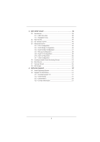
CPU Installation 16 2.2 Installation of CPU Fan and Heatsink 16 2.3 Installation of Memory Modules (DIMM 17 2.4 Expansion Slots (PCI and PCI Express Slots 19 2.5 CrossFireXTM and Quad CrossFireXTM Operation Guide 20 2.6 Surround Display Information 23 2.7 ASRock Smart Remote Installation Guide - ASRock 970 Extreme3 | User Manual - Page 4
OC Tweaker Screen 40 3.4 Advanced Screen 44 3.4.1 CPU Configuration 45 3.4.2 North Bridge Configuration 46 Boot Screen 54 3.7 Security Screen 55 3.8 Exit Screen 56 4. Software Support 57 4.1 Install Operating System 57 4.2 Support CD Information 57 4.2.1 Running Support CD 57 4.2.2 Drivers - ASRock 970 Extreme3 | User Manual - Page 5
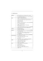
fic information about the model you are using. www.asrock.com/support/index.asp 1.1 Package Contents ASRock 970 Extreme3 Motherboard (ATX Form Factor: 12.0-in x 8.6-in, 30.5 cm x 21.8 cm) ASRock 970 Extreme3 Quick Installation Guide ASRock 970 Extreme3 Support CD 2 x Serial ATA (SATA) Data Cables - ASRock 970 Extreme3 | User Manual - Page 6
Power Phase Design - Supports CPU up to 140W - Supports AMD's Cool 'n' QuietTM Technology - FSB 2400 MHz (4.8 GT/s) - Supports Untied Overclocking Technology (see CAUTION 2) - Supports Hyper-Transport 3.0 (HT 3.0) Technology - Northbridge: AMD 970 - Southbridge: AMD SB950 - Dual Channel DDR3 Memory - ASRock 970 Extreme3 | User Manual - Page 7
header - 1 x HDMI_SPDIF header - 1 x Power LED header - CPU/Chassis/Power FAN connector - 24 pin ATX power connector - 8 pin 12V power connector - Front panel audio connector - 3 x USB 2.0 headers (support 6 USB 2.0 ports) - 32Mb AMI UEFI Legal BIOS with GUI support - Supports "Plug and Play" - ACPI - ASRock 970 Extreme3 | User Manual - Page 8
ready power supply is required) (see CAUTION 16) * For detailed product information, please visit our website: http://www.asrock.com WARNING Please realize that there is a certain risk involved with overclocking, including adjusting the setting in the BIOS, applying Untied Overclocking Technology - ASRock 970 Extreme3 | User Manual - Page 9
speed is supported depends on the AM3/AM3+ CPU you adopt. If you want to adopt DDR3 2100/1866/1800/1600 memory module on this motherboard, please refer to the memory support list on our website for the compatible memory modules. Non OC mode's DDR3 1866 is supported by AM3+ CPU. ASRock website: http - ASRock 970 Extreme3 | User Manual - Page 10
benefits. LAN Application Prioritization: You can configure your application priority ideally and/or add new programs. Lower Latency in Game: After setting online game priority higher, it can lower the latency in game. Traffic Shaping: You can watch Youtube HD video and download files simultaneously - ASRock 970 Extreme3 | User Manual - Page 11
you resume the system, please check if the CPU fan on the motherboard functions properly and unplug the power cord, then plug it back again. To improve heat dissipation, remember to spray thermal grease between the CPU and the heatsink when you install the PC system. 16. EuP, stands for Energy - ASRock 970 Extreme3 | User Manual - Page 12
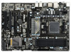
17 18 32 31 30 29 28 27 26 25 24 232221 20 19 1 ATX 12V Power Connector (ATX12V1) 2 Chassis Fan Connector (CHA_FAN3) 3 AM3+ CPU Socket 4 CPU Heatsink Retention Module 5 CPU Fan Connector (CPU_FAN2) 6 CPU Fan Connector (CPU_FAN1) 7 2 x 240-pin DDR3 DIMM Slots (Dual Channel: DDR3_A1, DDR3_B1; Black - ASRock 970 Extreme3 | User Manual - Page 13
(Pink) USB 3.0 Port (USB01) eSATA3 Connector USB 2.0 Ports (USB01) Optical SPDIF Out Port Coaxial SPDIF Out Port PS/2 Keyboard Port (Purple) * There are two LED next to the LAN port. LAN Port ** If you use 2-channel speaker, please connect the speaker's plug into "Front Speaker Jack". See - ASRock 970 Extreme3 | User Manual - Page 14
your computer, you will find "Mixer" tool on your system. Please select "Mixer ToolBox" , click "Enable playback multi-streaming", and click "ok". Choose "2CH", "4CH", "6CH", or "8CH" and then you are allowed to select "Realtek HDA Primary output" to use Rear Speaker, Central/Bass, and Front - ASRock 970 Extreme3 | User Manual - Page 15
any motherboard settings. Before you install or remove any component, ensure that the power is switched off or the power cord is detached from the power supply. Failure to do so may cause severe damage to the motherboard, peripherals, and/or components. 1. Unplug the power cord from the wall socket - ASRock 970 Extreme3 | User Manual - Page 16
that the CPU and the heatsink are securely fastened and in good contact with each other. Then connect the CPU fan to the CPU FAN connector (CPU_FAN1, see Page 12, No. 6 or CPU_FAN2, see Page 12, No. 5). For proper installation, please kindly refer to the instruction manuals of the CPU fan and the - ASRock 970 Extreme3 | User Manual - Page 17
DIMMs in all four slots. 1. Please install the memory module into the slots DDR3_A2 and DDR3_B2 for the first priority. 2. If you want to install two memory modules, for optimal compatibility and reliability, it is recommended to install them either in the set of slots DDR3_A1 and DDR3_B1, or in - ASRock 970 Extreme3 | User Manual - Page 18
Installing a DIMM Please make sure to disconnect power supply before adding or removing DIMMs or the system components. The DIMM only fits in one correct orientation. It will cause permanent damage to the motherboard and the DIMM if you force the DIMM into the slot at incorrect orientation. Step 3. - ASRock 970 Extreme3 | User Manual - Page 19
Please connect a chassis fan to motherboard chassis fan connector (CHA_FAN1, CHA_FAN2 or CHA_FAN3) when using multiple graphics cards for better thermal environment. Installing an expansion card Step 1. Before installing the expansion card, please make sure that the power supply is switched off or - ASRock 970 Extreme3 | User Manual - Page 20
Service Pack 2 / VistaTM / 7 OS. Quad CrossFireXTM feature are supported with Windows® VistaTM / 7 OS only. Please check AMD website for AMDTM CrossFireXTM driver updates. 1. If a customer incorrectly configures their system they will not see card manuals for detailed installation guide. Step - ASRock 970 Extreme3 | User Manual - Page 21
Bridge is provided with the graphics card you purchase, not bundled with this motherboard. Please refer to your graphics card vendor for details.) CrossFire Bridge or Step 3. Connect the DVI monitor cable to the DVI connector on the Radeon graphics card on PCIE2 slot. (You may use the DVI - ASRock 970 Extreme3 | User Manual - Page 22
tem. The Catalyst Uninstaller is an optional download. We recommend using this utility to uninstall any previously installed Catalyst drivers prior to installation. Please check AMD website for AMDTM driver updates. Step 3. Step 4. Step 5. Install the required drivers to your system. For Windows - ASRock 970 Extreme3 | User Manual - Page 23
technology, please check AMD website for updates and details. 2.6 Surround Display Feature This motherboard supports Surround Display upgrade. With the external add-on PCI Express VGA cards, you can easily enjoy the benefits of Surround Display feature. For the detailed instruction, please refer to - ASRock 970 Extreme3 | User Manual - Page 24
is compatible with most of the chassis on the market. 3. The Multi-Angle CIR Receiver does not support Hot-Plug function. Please install it before you boot the system. * ASRock Smart Remote is only supported by some of ASRock motherboards. Please refer to ASRock website for the motherboard support - ASRock 970 Extreme3 | User Manual - Page 25
cord from the power supply. After waiting for 15 seconds, use a jumper cap to short pin2 and pin3 on CLRCMOS1 for 5 seconds. However, please do not clear the CMOS right after you update the BIOS. If you need to clear the CMOS when you just finish updating the BIOS, you must boot up the system first - ASRock 970 Extreme3 | User Manual - Page 26
disk or the SATA3 connector on this motherboard. USB 2.0 Headers (9-pin USB_4_5) (see p.12 No. 26) (9-pin USB_6_7) (see p.12 No. 27) Besides four default USB 2.0 ports on the I/O panel, there are three USB 2.0 headers on this motherboard. Each USB 2.0 header can support two USB 2.0 ports. (9-pin - ASRock 970 Extreme3 | User Manual - Page 27
supports Jack Sensing, but the panel wire on the chassis must support HDA to function correctly. Please follow the instruction in our manual and chassis manual to install pin PANEL1) (see p.12 No. 23) This header accommodates several system front panel functions. Connect the power switch, reset - ASRock 970 Extreme3 | User Manual - Page 28
the pin assign-ments are matched correctly. Chassis Speaker Header (4-pin SPEAKER 1) (see p.12 No. 24) Power LED Header (3-pin PLED1) (see p.12 No. 22) 1 PLEDPLED+ PLED+ Chassis and Power Fan Connectors (4-pin CHA_FAN1) (see p.12 No. 12) GND +12V CHA_FAN_SPEED FAN_SPEED_CONTROL (3-pin CHA_FAN2 - ASRock 970 Extreme3 | User Manual - Page 29
If you plan to connect the 3-Pin CPU fan to the CPU fan connector on this motherboard, please connect it to Pin 1-3. Pin 1-3 Connected 3-Pin Fan Installation (3-pin CPU_FAN2) (see p.12 No. 5) GND +12V CPU_FAN_SPEED ATX Power Connector (24-pin ATXPWR1) (see p.12 No. 9) 12 24 Please connect an - ASRock 970 Extreme3 | User Manual - Page 30
HDMI_SPDIF Header (2-pin HDMI_SPDIF1) (see p.12 No. 31) 1 GND SPDIFOUT HDMI_SPDIF header, providing SPDIF audio output to HDMI VGA card, allows the system to connect HDMI Digital TV/ projector/LCD devices. Please connect the HDMI_SPDIF connector of HDMI VGA card to this header. 30 - ASRock 970 Extreme3 | User Manual - Page 31
Hard Disks Installation This motherboard adopts AMD SB950 chipset that supports Serial ATA3 (SATA3) hard disks and RAID (RAID 0, RAID 1, RAID 5 and RAID 10) functions. You may install SATA3 hard disks on this motherboard for internal storage devices. This section will guide you to install the SATA3 - ASRock 970 Extreme3 | User Manual - Page 32
Please make sure the SATA3 driver is installed into system properly. The latest SATA3 driver is available on our support website: www.asrock.com 4. Make sure to use the SATA power cable & data cable, which are from our motherboard package. 5. Please follow below instructions step by step to reduce - ASRock 970 Extreme3 | User Manual - Page 33
instruction sequence to process the Hot Plug, improper procedure will cause the SATA3 HDD damage and data loss. Step 1 Please connect SATA power cable 1x4-pin Step 2 Connect SATA data cable to end (White) to the power supply 1x4-pin the motherboard's SATAII / SATA3 cable. connector. SATA power - ASRock 970 Extreme3 | User Manual - Page 34
screen Storage Configuration. B. Set the "SATA Mode" option to [RAID]. STEP 2: Make a SATA3 Driver Diskette. (Please use USB floppy or floppy disk.) A. Insert the ASRock Support CD into your optical drive to boot your system. B. During POST at the beginning of system boot-up, press key - ASRock 970 Extreme3 | User Manual - Page 35
to [RAID]. STEP 2: Use "RAID Installation Guide" to set RAID configuration. Before you start to configure RAID function, you need to check the RAID installation guide in the Support CD for proper configuration. Please refer to the BIOS RAID installation guide part of the document in the following - ASRock 970 Extreme3 | User Manual - Page 36
UEFI SETUP UTILITY Advanced screen Storage Configuration. B. Set the "SATA Mode" option to [AHCI]. STEP 2: Make a SATA3 Driver Diskette. (Please use USB floppy or floppy disk.) Make a SATA3 driver diskette by following section 2.14.1 step 2 on page 34. STEP 3: Install Windows® XP / XP 64-bit OS on your - ASRock 970 Extreme3 | User Manual - Page 37
motherboard supports Untied Overclocking Technology, which means during overclocking, FSB enjoys better margin due to fixed PCI / PCIE buses. Before you enable Untied Overclocking function, please enter "Overclock Mode" option of UEFI setup to set the selection from [Auto] to [Manual]. Therefore, CPU - ASRock 970 Extreme3 | User Manual - Page 38
has a menu bar with the following selections: Main To set up the system time/date information OC Tweaker To set up overclocking features Advanced To set up the advanced UEFI features H/W Monitor To display current hardware status Boot To set up the default system device to locate and load the - ASRock 970 Extreme3 | User Manual - Page 39
right to select Screens Moves cursor up or down to select items To change option for the selected items To bring up the selected screen To display the General Help Screen To load optimal default values for all the settings To save changes and exit the UEFI SETUP UTILITY To jump to the - ASRock 970 Extreme3 | User Manual - Page 40
is [Manual]. CPU Configuration Overclock Mode Use this to select Overclock Mode. Configuration options: [Auto] and [Manual]. The default value is [Auto]. Spread Spectrum This item should always be [Auto] for better system stability. ASRock UCC ASRock UCC (Unlock CPU Core) feature simplifies AMD CPU - ASRock 970 Extreme3 | User Manual - Page 41
will display Processor Maximum Voltage for reference. Multiplier/Voltage Change This item is set to [Auto] by default. If it is set to [Manual], you guration options: [Auto], [8 Bit] and [16 Bit]. DRAM Configuration DRAM Frequency If [Auto] is selected, the motherboard will detect the memory module - ASRock 970 Extreme3 | User Manual - Page 42
access contention. Channel Interleaving It allows you to enable Channel Memory Interleaving. Configuration options: [Disabled], [Auto]. The default value is [Auto]. CAS# Latency (tCL) Use this item to change CAS# Latency (tCL) Auto/Manual setting. The default is [Auto]. RAS# to CAS# Delay (tRCD) Use - ASRock 970 Extreme3 | User Manual - Page 43
) Auto/Manual setting. The CPU VDDA Voltage. The default value is [Auto]. PCIE VDDA Voltage Use this to select PCIE VDDA Voltage. The default value is [Auto]. SB Voltage Use this to select SB Voltage. The default value is [Auto]. Would you like to save current setting user defaults? In this option - ASRock 970 Extreme3 | User Manual - Page 44
set the configurations for the following items: CPU Configuration, Nouth Bridge Configuration, South Bridge Configuration, Storage Configuration, Super IO Configuration, ACPI Configuration, and USB Configuration. Setting file to your USB flash drive, floppy disk or hard drive, then you can update your UEFI only - ASRock 970 Extreme3 | User Manual - Page 45
enabling this function may reduce CPU voltage and memory frequency, and lead to system stability or compatibility issue with some memory modules or power supplies. Please set this item to [Disable] if above issue occurs. Secure Virtual Machine When this option is set to [Enabled], a VMM (Virtual - ASRock 970 Extreme3 | User Manual - Page 46
Bus scanning order while searching for video card. It allows you to select the type of Primary VGA in case of multiple video controllers. The default value of this feature is [PCI Express]. Configuration options: [PCI] and [PCI Express]. IOMMU Use this to enable or disable IOMMU. The default value of - ASRock 970 Extreme3 | User Manual - Page 47
you want to enable Deep Sx, please disable On/Off Play first. Onboard LAN This allows you to enable or disable the onboard LAN feature. Good Night LED Enable this option to turn off Power LED and LAN LED when the system is power on. The keyboard LED will also be turned off in S1, S3 and - ASRock 970 Extreme3 | User Manual - Page 48
Mode Use this item to adjust SATA Mode. The default value of this option is [IDE Mode]. Configuration options: [AHCI Mode], [RAID Mode] and [IDE Mode]. If you set this item to RAID mode, it is suggested to install SATA ODD driver on SATA3_5 and eSATA3 ports. SATA IDE Combined Mode This item is - ASRock 970 Extreme3 | User Manual - Page 49
Serial Port Use this item to enable or disable the onboard serial port. Serial Port Address Use this item to set the address for the onboard serial port. Configuration options: [3F8h / IRQ4] and [3E8h / IRQ4]. Infrared Port Use this item to enable or disable the onboard infrared port. Infrared Port - ASRock 970 Extreme3 | User Manual - Page 50
Loss This allows you to set the power state after an unexpected AC/power loss. If [Power Off] is selected, the AC/power remains off when the power recovers. If [Power On] is selected, the AC/power resumes and the system starts to boot up when the power recovers. PS/2 Keyboard Power On Use this item - ASRock 970 Extreme3 | User Manual - Page 51
ACPI HPET table Use this item to enable or disable ACPI HPET Table. The default value is [Enabled]. Please set this option to [Enabled] if you plan to use this motherboard to submit Windows® VistaTM certification. 51 - ASRock 970 Extreme3 | User Manual - Page 52
. If you have USB compatibility issue, it is recommended to select [Disabled] to enter OS. [UEFI Setup Only] - USB devices are allowed to use only under UEFI setup and Windows / Linux OS. Legacy USB 3.0 Support Use this option to enable or disable legacy support for USB 3.0 devices. The default - ASRock 970 Extreme3 | User Manual - Page 53
hardware on your system, including the parameters of the CPU temperature, motherboard temperature, CPU fan speed, chassis fan speed, and the critical voltage. CPU Fan 1 & 2 Setting This allows you to set the CPU fan 1 & 2 speed. Confi guration options: [Full On] and [Automatic Mode]. The default is - ASRock 970 Extreme3 | User Manual - Page 54
Screen In this section, it will display the available devices on your system for you to configure the boot settings and the boot priority. Setup Prompt Timeout This shows the number of seconds to wait for setup activation key. 65535(0xFFFF) means indefinite waiting. Bootup Num-Lock If - ASRock 970 Extreme3 | User Manual - Page 55
3.7 Security Screen In this section, you may set or change the supervisor/user password for the system. For the user password, you may also clear it. 55 - ASRock 970 Extreme3 | User Manual - Page 56
figuration changes and exit setup?" Select [OK] to save the changes and exit the UEFI SETUP UTILITY. Discard Changes and Exit When you select this option, it will pop-out the following message, "Discard changes and exit setup?" Select [OK] to exit the UEFI SETUP UTILITY without saving any changes - ASRock 970 Extreme3 | User Manual - Page 57
display the menus. 4.2.2 Drivers Menu The Drivers Menu shows the available devices drivers if the system detects the installed devices. Please install the necessary drivers to activate the devices. 4.2.3 Utilities Menu The Utilities Menu shows the applications software that the motherboard supports - ASRock 970 Extreme3 | User Manual - Page 58
or at system POST. Set AHCI Mode in UEFI Setup Utility > Advanced > Storage Configuration > SATA Mode. 3. Choose the item "UEFI:xxx" to boot in UEFI Setup Utility > Boot > Boot Option #1. ("xxx" is the device which contains your Windows® installation files. Normally it is an optical - ASRock 970 Extreme3 | User Manual - Page 59
adopting UEFI BIOS that allows Windows® OS to be installed on a large size HDD (>2TB). Please follow below procedure to install the operating system. 1. Please make sure to use Windows® VistaTM 64-bit (with SP1 or above) or Windows® 7 64-bit. 2. Press or at system POST. Set RAID Mode - ASRock 970 Extreme3 | User Manual - Page 60
7. And then key in drvcfg -s [Drv number] [Ctrl number] to enter Raid Utility. For example: key in drvcfg -s 4E B5. 8. Choose Logical Drive Main Menu to set up Raid Drive. 9. Choose Logical Drive Create Menu to create a Raid Drive. 10. Choose Usable Physical Drive List to select Raid HDD. 60 - ASRock 970 Extreme3 | User Manual - Page 61
toggle checkbox. 12. Choose Ld Size setting, and key in the Raid size. 13. After set up Raid size, please click Start to Create. 14. Press to exit Utility. 15. During reboot, please press to enter Boot Manual. Choose UEFI: SCSI CD/DVD Drive. * This option only shows on Windows® 7 64-bit - ASRock 970 Extreme3 | User Manual - Page 62
® Installation Guide to install OS. If you install Windows® 7 64-bit / VistaTM 64-bit in a large hard disk (ex. Disk volume > 2TB), it may take more time to boot into Windows® or install driver/ utilities. If you encounter this problem, you will need to following instructions to fix this problem - ASRock 970 Extreme3 | User Manual - Page 63
B. Disable "Volume Shadow Copy" service. a. Type "computer management" in the Start Menu, then press "Enter". b. Go to "Services and Applications>Services"; Then double click "Volume Shadow Copy". c. Set "Startup type" to "Disable" then Click "OK". 63 - ASRock 970 Extreme3 | User Manual - Page 64
your system. D. After reboot, please start to install motherboard drivers and utilities. Windows® 7 64-bit: A. Please request the hotfix KB2505454 thru this link: http://support.microsoft.com/kb/2505454/ B. After installing Windows® 7 64-bit, install the hotfix kb2505454. (This may take long time
-
 1
1 -
 2
2 -
 3
3 -
 4
4 -
 5
5 -
 6
6 -
 7
7 -
8
-
9
-
10
-
11
-
12
-
13
-
14
-
15
-
16
-
17
-
18
-
19
-
20
-
21
-
22
-
23
-
24
-
25
-
26
-
27
-
28
-
29
-
30
-
31
-
32
-
33
-
34
-
35
-
36
-
37
-
38
-
39
-
40
-
41
-
42
-
43
-
44
-
45
-
46
-
47
-
48
-
49
-
50
-
51
-
52
-
53
-
54
-
55
-
56
-
57
-
58
-
59
-
60
-
61
-
62
-
63
-
64
 |
 |
1
970 Extreme3
User Manual
Version 1.0
Published August 2011
Copyright©2011 ASRock INC. All rights reserved.