ASRock 970 Extreme4 User Manual
ASRock 970 Extreme4 Manual
 |
View all ASRock 970 Extreme4 manuals
Add to My Manuals
Save this manual to your list of manuals |
ASRock 970 Extreme4 manual content summary:
- ASRock 970 Extreme4 | User Manual - Page 1
970 Extreme4 User Manual Version 1.0 Published May 2011 Copyright©2011 ASRock INC. All rights reserved. 1 - ASRock 970 Extreme4 | User Manual - Page 2
by ASRock. ASRock assumes no responsibility for any errors or omissions that may appear in this manual. With respect to the contents of this manual, ASRock does The Lithium battery adopted on this motherboard contains Perchlorate, a toxic substance controlled in Perchlorate Best Management Practices - ASRock 970 Extreme4 | User Manual - Page 3
20 2.6 CrossFireXTM, 3-Way CrossFireXTM and Quad CrossFireXTM Operation Guide 23 2.7 Surround Display Information 28 2.8 ASRock Smart Remote Installation Guide 29 2.9 Jumpers Setup 30 2.10 Onboard Headers and Connectors 31 2.11 Smart Switches 36 2.12 Dr. Debug 37 2.13 Serial ATA3 (SATA3 - ASRock 970 Extreme4 | User Manual - Page 4
OC Tweaker Screen 50 3.4 Advanced Screen 54 3.4.1 CPU Conf guration 55 3.4.2 North Bridge Conf guration 56 Boot Screen 64 3.7 Security Screen 65 3.8 Exit Screen 66 4. Software Support 67 4.1 Install Operating System 67 4.2 Support CD Information 67 4.2.1 Running Support CD 67 4.2.2 Drivers - ASRock 970 Extreme4 | User Manual - Page 5
5mm Audio Cable (Optional) 1 x I/O Panel Shield ASRock Reminds You... To get better performance in Windows ® 7 / 7 64-bit / V istaTM / VistaTM 64 bit, it is recommended to set the BIOS option in Storage Con f guration to AHCI mode. For the BIOS setup, please refer to the "User Manual" in our support - ASRock 970 Extreme4 | User Manual - Page 6
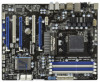
Platform CPU Chipset Memory Expansion Slot Audio LAN - ATX Form Factor: 12.0-in x 9.6-in, 30.5 cm x 24.4 cm - All Solid Capacitor design (100% Japan-made high-quality Conductive Polymer Capacitors) - Support for Socket AM3+ processors - Support for Socket AM3 processors: AMD PhenomTM - ASRock 970 Extreme4 | User Manual - Page 7
) - 1 x IEEE 1394 Port - 1 x Clear CMOS Switch with LED - HD Audio Jack: Side Speaker/Rear Speaker/Central/Bass/ Line in/Front Speaker/Microphone (see CAUTION 6) - 5 x SATA3 6.0 Gb/s connectors by AMD SB950, support RAID(RAID 0, RAID 1, RAID 0+1, JBOD and RAID 5), NCQ, AHCI and "Hot Plug" functions - ASRock 970 Extreme4 | User Manual - Page 8
Support CD - Drivers, Utilities, AntiVirus Software (Trial Version), CyberLink MediaEspresso 6.5 Trial, AMD Fusion, AMD Fusion Media Explorer, ASRock Software Suite (CyberLink DVD Suite - OEM and Trial) Unique Feature - ASRock Extreme Tuning Utility (AXTU) (see CAUTION 7) - ASRock Instant Boot - ASRock 970 Extreme4 | User Manual - Page 9
/1866/1800/1600MHz memory speed is supported depends on the AM3/AM3+ CPU you adopt. If you want to adopt DDR3 2000/1866/1800/1600 memory module on this motherboard, please refer to the memory support list on our website for the compatible memory modules. ASRock website: http://www.asrock.com 5. Due - ASRock 970 Extreme4 | User Manual - Page 10
in Flash ROM. This convenient BIOS update tool allows you to update system BIOS without entering operating systems f rst like MS-DOS or Windows ®. With this utility, you can press key during the POST or press key to BIOS setup menu to access ASRock Instant Flash. Just launch this tool - ASRock 970 Extreme4 | User Manual - Page 11
be under 1.00W in off mode condition. To meet EuP standard, an EuP ready motherboard and an EuP ready power supply are required. According to Intel's suggestion, the EuP ready power supply must meet the standard of 5v standby power ef f ciency is higher than 50% under 100 mA current consumption. For - ASRock 970 Extreme4 | User Manual - Page 12
41 40 39 38 37 36 35 34 Designed in Taipei Top: LINE IN Center: FRONT Bottom: MIC IN USB_12_13 HD_AUDIO1 PCIE1 AMD 970 Chipset PCIE2 AUDIO CODEC PCI1 PCIE3 CMOS BATTERY Super I/O 32Mb BIOS HDMI_SPDIF1 IR1 1 1 COM1 PCIE4 PCI2 PCIE5 USB_10_11 USB_8_9 1 1 970 Extreme4 SATA3 6Gb - ASRock 970 Extreme4 | User Manual - Page 13
Front Speaker (Lime) 9 Microphone (Pink) 10 11 *** 12 13 14 15 16 17 USB 3.0 Port (USB45) IEEE 1394 Port (IEEE 1394) eSATA3 Connector USB 2.0 Ports (USB01) Clear CMOS Switch of speaker you use. TABLE for Audio Output Connection Audio Output Channels Front Speaker Rear Speaker Central / Bass Side - ASRock 970 Extreme4 | User Manual - Page 14
"ok". Choose "2CH", "4CH", "6CH", or "8CH" and then you are allowed to select "Realtek HDA Primary output" to use Rear Speaker, Central/Bass, and Front Speaker, or select "Realtek HDA Audio 2nd output" to use front panel audio. *** eSATA3 connector supports SATA Gen3 in cable 1M. 14 - ASRock 970 Extreme4 | User Manual - Page 15
Take note of the following precautions before you install motherboard components or change any motherboard settings. Before you install or remove any component, ensure that the power is switched of f or the power cord is detached from the power supply. Failure to do so may cause severe damage - ASRock 970 Extreme4 | User Manual - Page 16
Triangle 2.2 Installation of CPU Fan and Heatsink After you install the CPU into this motherboard, it is necessary to CPU fan to the CPU FAN connector (CPU_FAN1, see Page 12, No. 4 or CPU_F AN2, see Page 12, No. 3). For proper installation, please kindly refer to the instruction manuals of the CPU - ASRock 970 Extreme4 | User Manual - Page 17
2.3 Installation of Memory Modules (DIMM) This motherboard provides four 240-pin DDR3 (Double Data Rate 3) DIMM slots, and supports Dual Channel Memory Technology. For dual channel conf guration, you always need to install identical (the same brand, speed, size and chip-type) DDR3 DIMM pair in the - ASRock 970 Extreme4 | User Manual - Page 18
Installing a DIMM Please make sure to disconnect power supply before adding or removing DIMMs or the system components The DIMM only f ts in one correct orientation. It will cause permanent damage to the motherboard and the DIMM if you force the DIMM into the slot at incorrect orientation. Step 3. - ASRock 970 Extreme4 | User Manual - Page 19
graphics cards to support SLITM and CrossFireXTM power supply is switched off or the power cord is unplugged. Please read the documentation of the expansion card and make necessary hardware settings for the card before you start the installation. Remove the system unit cover (if your motherboard - ASRock 970 Extreme4 | User Manual - Page 20
2.5 SLITM Operation Guide This motherboard supports NVIDIA® SLITM technology (Scalable Link Interface) that allows you to install up to three identical PCI Express x16 graphics cards. Currently , NVIDIA® SLITM technology supports Windows ® XP / XP 64-bit / V istaTM / VistaTM 64bit / 7 / 7 64-bit OS. - ASRock 970 Extreme4 | User Manual - Page 21
the graphics card drivers to your system. After that, you can enable the MultiGraphics Processing Unit (GPU) feature in the NVIDIA® nView system tray utility. Please follow the procedures below to enable the multi-GPU feature. For Windows® XP / XP 64-bit OS: A. Double-click NVIDIA Settings icon on - ASRock 970 Extreme4 | User Manual - Page 22
Click the Start icon on your Windows taskbar. B. From the pop-up menu, select All Programs, and then click NVIDIA Corporation. C. Select NVIDIA Control Panel tab. D. Select Control Panel tab. E. From the pop-up menu, select Set SLI and PhysX configuration. In Set PhysX GPU acceleration item, please - ASRock 970 Extreme4 | User Manual - Page 23
image quality in any 3D application. Currently CrossFireXTM feature is supported with Windows® XP with Service Pack 2 / VistaTM / 7 OS. 3-way CrossFireXTM and Quad CrossFireXTM feature are supported with Windows ® VistaTM / 7 OS only . Please check AMD website for AMDTM CrossFireXTM driver updates - ASRock 970 Extreme4 | User Manual - Page 24
Bridge is provided with the graphics card you purchase, not bundled with this motherboard. Please refer to your graphics card vendor for details.) CrossFire Bridge or Step 3. Connect the DVI monitor cable to the DVI connector on the Radeon graphics card on PCIE2 slot. (You may use the DVI - ASRock 970 Extreme4 | User Manual - Page 25
Bridge to connect Radeon graphics cards on PCIE4 and PCIE5 slots. (CrossFireTM Bridge is provided with the graphics card you purchase, not bundled with this motherboard. Please refer to your graphics card vendor for details.) 25 - ASRock 970 Extreme4 | User Manual - Page 26
CrossFireTM Bridge Step 5. Connect the DVI monitor cable to the DVI connector on the Radeon graphics card on PCIE2 slot. (You may use the DVI to D-Sub adapter to convert the DVI connector to D-Sub interface, and then connect the D-Sub monitor cable to the DVI to D-Sub adapter.) 26 - ASRock 970 Extreme4 | User Manual - Page 27
prior to installation. Please check AMD website for AMDTM driver updates. Step 3. Step 4. Step 5. Install the required drivers to your system. For Windows® XP OS: A. AMDTM recommends Windows® XP Service Pack 2 or higher to be installed (If you have Windows® XP Service Pack 2 or higher installed in - ASRock 970 Extreme4 | User Manual - Page 28
in "ATI Catalyst Control Center" is AMD website for updates and details. 2.7 Surround Display Feature This motherboard supports Surround Display upgrade. With the external add-on PCI Express VGA cards, you can easily enjoy the benef ts of Surround Display feature. For the detailed instruction - ASRock 970 Extreme4 | User Manual - Page 29
, down and front), which is compatible with most of the chassis on the market. 3. The Multi-Angle CIR Receiver does not support Hot-Plug function. Please install it before you boot the system. * ASRock Smart Remote is only supported by some of ASRock motherboards. Please refer to ASRock website for - ASRock 970 Extreme4 | User Manual - Page 30
please do not clear the CMOS right after you update the BIOS. If you need to clear the CMOS when you just f nish updating the BIOS, you must boot up the system f rst, and then shut it down before you do the clear-CMOS action. The Clear CMOS Switch has the same function as the Clear CMOS jumper. 30 - ASRock 970 Extreme4 | User Manual - Page 31
end of the 3.5mm audio cable can be connected to the portable audio devices, such as MP3 player and mobile phone or the Line-in port of your PC. Besides four default USB 2.0 ports on the I/O panel, there are three USB 2.0 headers on this motherboard. Each USB 2.0 header can support two USB 2.0 ports - ASRock 970 Extreme4 | User Manual - Page 32
) (see p.12 No. 28) Front Panel Audio Header (9-pin HD_AUDIO1) (see p.12 No. 42) This header supports an optional wireless transmitting and receiving infrared module. This header can be used to connect the remote controller receiver. This is an interface for the front panel audio cable that allows - ASRock 970 Extreme4 | User Manual - Page 33
For Windows® 7 / 7 64-bit / VistaTM / VistaTM 64-bit OS: Go to the "FrontMic" Tab in the Realtek Control panel. Adjust "Recording Volume". System Panel Header (9-pin PANEL1) (see p.12 No. 21) This header accommodates several system front panel functions. Connect the power switch, reset switch and - ASRock 970 Extreme4 | User Manual - Page 34
The front panel design may differ by chassis. A front panel module mainly consists of power switch, reset switch, power LED, hard drive activity LED, speaker and etc. When connecting your chassis front panel module to this header, make sure the wire assignments and the pin assign-ments are matched - ASRock 970 Extreme4 | User Manual - Page 35
speed control function. If you plan to connect the 3-Pin CPU fan to the CPU fan connector on this motherboard, please connect it to Pin 1-3. Pin 1-3 Connected 3-Pin Fan Installation (3-pin CPU_FAN2) (see p.12 No. 3) +12V GND CPU_FAN_SPEED ATX Power Connector (24-pin ATXPWR1) (see p.12 No. 10) 12 - ASRock 970 Extreme4 | User Manual - Page 36
header. 2.11 Smart Switches This motherboard has three smart switches: power switch, reset switch and clear CMOS switch, allowing users to quickly turn on/off or reset the system or clear the CMOS values. Power Switch (PWRBTN) (see p.12 No. 23) Power Switch is a smart switch, allowing users to - ASRock 970 Extreme4 | User Manual - Page 37
Codes section below) Memory Installed CPU post-memory initialization is started CPU post-memory initialization. Cache initialization CPU post-memory initialization. Application Processor(s) (AP) initialization CPU post-memory initialization. Boot Strap Processor (BSP) selection CPU post-memory - ASRock 970 Extreme4 | User Manual - Page 38
test failed or possible CPU cache error CPU micro-code is not found or micro-code update is failed Internal CPU error reset PPI is not available Reserved for future AMI error codes S3 Resume is stared (S3 Resume PPI is called by the DXE IPL) S3 Boot Script execution Video repost OS S3 wake vector - ASRock 970 Extreme4 | User Manual - Page 39
module initialization CSM initialization Reserved for future AMI DXE codes OEM DXE initialization codes Boot Device Selection (BDS) phase is started Driver connecting is started PCI Bus initialization is started PCI Bus Hot Plug Controller Initialization PCI Bus Enumeration PCI Bus Request Resources - ASRock 970 Extreme4 | User Manual - Page 40
Boot Services event Runtime Set Virtual Address MAP Begin Runtime Set Virtual Address MAP End Legacy Option ROM Initialization System Reset USB hot plug PCI bus hot plug Clean-up of NVRAM Conf guration Reset (reset of NVRAM settings) Reserved for future AMI codes OEM BDS initialization codes CPU - ASRock 970 Extreme4 | User Manual - Page 41
Functions for SATA3 HDDs This motherboard supports Hot Plug and Hot Swap functions for SA TA3 in RAID / AHCI mode. AMD SB950 chipset provides hardware support for Advanced Host controller Interface (AHCI), a new programming interface for SA TA host controllers developed thru a joint industry effort - ASRock 970 Extreme4 | User Manual - Page 42
is installed into system properly. The latest SATA3 driver is available on our support website: www.asrock.com 4. Make sure to use the SATA power cable & data cable, which are from our motherboard package. 5. Please follow below instructions step by step to reduce the risk of HDD crash or data - ASRock 970 Extreme4 | User Manual - Page 43
: Please do follow below instruction sequence to process the Hot Plug, improper procedure will cause the SATA3 HDD damage and data loss. Step 1 Please connect SATA power cable 1x4-pin Step 2 Connect SATA data cable to end (White) to the power supply 1x4-pin the motherboard's SATAII / SATA3 cable - ASRock 970 Extreme4 | User Manual - Page 44
B. Set the "SATA Mode" option to [RAID]. STEP 2: Make a SATA3 Driver Diskette. (Please use USB floppy or floppy disk.) A. Insert the ASRock Support CD into your optical drive to boot your system. B. During POST at the beginning of system boot-up, press key, and then a window for boot devices - ASRock 970 Extreme4 | User Manual - Page 45
BIOS RAID installation guide part of the document in the following path in the Support CD: .. \ RAID Installation Guide STEP 3: Make a SATA3 Driver Diskette. (Please use USB floppy or floppy disk.) Make a SATA3 driver diskette by following section 2.17.1 step 2 on page 44. STEP 4: Install Windows - ASRock 970 Extreme4 | User Manual - Page 46
bit OS on your system. At the beginning of Windows® setup, press F6 to install a third-party AHCI driver. When prompted, insert the SA TA3 driver diskette containing the AMD AHCI driver. After reading the f oppy disk, the driver will be presented. Select the driver to install according to the OS you - ASRock 970 Extreme4 | User Manual - Page 47
Storage Conf guration. B. Set the "SATA Mode" option to [IDE]. STEP 2: Install Windows® 7 / 7 64-bit / VistaTM / VistaTM 64-bit OS on your sys- tem. 2.19 Untied Overclocking Technology This motherboard supports Untied Overclocking Technology, which means during overclocking, FSB enjoys better margin - ASRock 970 Extreme4 | User Manual - Page 48
gure your system. The SPI Memory on the motherboard stores the UEFI SETUP UTILITY. You may run the UEFI SETUP UTILITY when you start up the computer . Please press or during the Power-On-Self-Test (POST) to enter the UEFI SETUP UTILITY, otherwise, POST will continue with its test routines - ASRock 970 Extreme4 | User Manual - Page 49
option for the selected items To bring up the selected screen To display the General Help Screen To load optimal default values for all the settings To save changes and exit the UEFI SETUP UTILITY To jump to the Exit Screen or exit the current screen 3.2 Main Screen When you enter - ASRock 970 Extreme4 | User Manual - Page 50
to select Overclock Mode. Configuration options: [Auto] and [Manual]. The default value is [Auto]. Spread Spectrum This item should always be [Auto] for better system stability. ASRock UCC ASRock UCC (Unlock CPU Core) feature simpli f es AMD CPU activation. As long as a simple switch of the UEFI - ASRock 970 Extreme4 | User Manual - Page 51
item is set to [Auto] by default. If it is set to [Manual], you may adjust the value of Processor Frequency and Processor Voltage. ] is selected, the motherboard will detect the memory module(s) inserted and assigns appropriate frequency automatically. DRAM Timing Control Power Down Enable Use this - ASRock 970 Extreme4 | User Manual - Page 52
) Use this item to change Read to Precharge (tRTP) Auto/Manual setting. The default is [Auto]. Four Activate Window (tFAW) Use this item to change Four Activate Window (tFAW) Auto/Manual setting. The default is [Auto]. Voltage Control DRAM Voltage Use this to select DRAM Voltage. The default value - ASRock 970 Extreme4 | User Manual - Page 53
Voltage Use this to select CPU VDDA Voltage. The default value is [Auto]. PCIE VDDA Voltage Use this to select PCIE VDDA Voltage. The default value is [Auto]. SB Voltage Use this to select SB Voltage. The default value is [Auto]. Would you like to save current setting user defaults? In this - ASRock 970 Extreme4 | User Manual - Page 54
guration. Setting wrong values in this section may cause the system to malfunction. Instant Flash Instant Flash is a UEFI f ash utility embedded in Flash ROM. This convenient UEFI update tool allows you to update system UEFI without entering operating systems f rst like MS-DOS or Windows ®. Just - ASRock 970 Extreme4 | User Manual - Page 55
state is supported through the native processor instructions HLT and MWAIT and requires no hardware support from the chipset. In the C1 power state, the processor maintains the context of the system caches. CPU Thermal Throttle Use this item to enable CPU internal thermal control mechanism to keep - ASRock 970 Extreme4 | User Manual - Page 56
3.4.2 North Bridge Configuration Primary Graphics Adapter This item will switch the PCI Bus scanning order while searching for video card. It allows you to select the type of Primary VGA in case of multiple video controllers. The default value of this feature is [PCI Express]. Conf guration options: - ASRock 970 Extreme4 | User Manual - Page 57
Select [Auto], [Enabled] or [Disabled] for the onboard HD Audio feature. If you select [Auto], the onboard HD Audio will be disabled when PCI Sound Card is plugged. Front Panel Select [Auto] or [Disabled] for the onboard HD Audio Front Panel. On/Off Play Use this item to enable or disable On/Off - ASRock 970 Extreme4 | User Manual - Page 58
or disable the "SATA Controller" feature. SATA Mode Use this item to adjust SATA Mode. The default value of this option is [IDE Mode]. Conf guration options: [AHCI Mode], [RAID Mode] and [IDE Mode]. If you set this item to RAID mode, it is suggested to install SATA ODD driver on SATA3_5 and eSATA3 - ASRock 970 Extreme4 | User Manual - Page 59
3.4.5 Super IO Configuration Serial Port Use this item to enable or disable the onboard serial port. Serial Port Address Use this item to set the address for the onboard serial port. Con f guration options: [3F8h / IRQ4] and [3E8h / IRQ4]. Infrared Port Use this item to enable or disable the - ASRock 970 Extreme4 | User Manual - Page 60
to RAM Use this item to select whether to auto-detect or disable the Suspend-toRAM feature. Select [Auto] will enable this feature if the OS supports it. Check Ready Bit Use this item to enable or disable the feature Check Ready Bit. Restore on AC/Power Loss This allows you to set the power - ASRock 970 Extreme4 | User Manual - Page 61
USB Mouse Power On Use this item to enable or disable the system to wake from S5 using USB Mouse. ACPI HPET table Use this item to enable or disable ACPI HPET Table. The default value is [Enabled]. Please set this option to [Enabled] if you plan to use this motherboard to submit Windows® VistaTM - ASRock 970 Extreme4 | User Manual - Page 62
OS and UEFI setup when [Disabled] is selected. If you have USB compatibility issue, it is recommended to select [Disabled] to enter OS. [UEFI Setup Only] - USB devices are allowed to use only under UEFI setup and Windows / Linux OS. Legacy USB 3.0 Support Use this option to enable or disable legacy - ASRock 970 Extreme4 | User Manual - Page 63
on your system, including the parameters of the CPU temperature, motherboard temperature, CPU fan speed, chassis fan speed, and the critical voltage. CPU Fan 1 & 2 Setting This allows you to set the CPU fan 1 & 2 speed. Conf guration options: [Full On] and [Automatic Mode]. The default is value - ASRock 970 Extreme4 | User Manual - Page 64
to wait for setup activation key. 65535(0xFFFF) means indef nite waiting. Bootup Num-Lock If this item is set to [On], it will automatically activate the Numeric Lock function after boot-up. Full Screen Logo Use this item to enable or disable OEM Logo. The default value is [Enabled]. AddOn ROM - ASRock 970 Extreme4 | User Manual - Page 65
3.7 Security Screen In this section, you may set or change the supervisor/user password for the system. For the user password, you may also clear it. 65 - ASRock 970 Extreme4 | User Manual - Page 66
3.8 Exit Screen Save Changes and Exit When you select this option, it will pop-out the following message, "Save conf guration changes and exit setup?" Select [OK] to save the changes and exit the UEFI SETUP UTILITY. Discard Changes and Exit When you select this option, it will pop-out the following - ASRock 970 Extreme4 | User Manual - Page 67
4.1 Install Operating System This motherboard supports various Microsoft® Windows® operating systems: 7 / 7 64-bit / V istaTM / V istaTM 64-bit / XP / XP 64-bit. Because motherboard settings and hardware options vary, use the setup procedures in this chapter for general reference only. Refer to - ASRock 970 Extreme4 | User Manual - Page 68
Than 2TB This motherboard is adopting UEFI BIOS that allows Windows ® OS to be installed on a large size HDD (>2TB). Please follow below procedure to install the operating system. 1. Please make sure to use Windows® VistaTM 64-bit (with SP1 or above) or Windows® 7 64-bit. 2. Set AHCI Mode in UEFI
-
 1
1 -
 2
2 -
 3
3 -
 4
4 -
 5
5 -
 6
6 -
 7
7 -
8
-
9
-
10
-
11
-
12
-
13
-
14
-
15
-
16
-
17
-
18
-
19
-
20
-
21
-
22
-
23
-
24
-
25
-
26
-
27
-
28
-
29
-
30
-
31
-
32
-
33
-
34
-
35
-
36
-
37
-
38
-
39
-
40
-
41
-
42
-
43
-
44
-
45
-
46
-
47
-
48
-
49
-
50
-
51
-
52
-
53
-
54
-
55
-
56
-
57
-
58
-
59
-
60
-
61
-
62
-
63
-
64
-
65
-
66
-
67
-
68
 |
 |
1
970 Extreme4
User Manual
Version 1.0
Published May 2011
Copyright©2011 ASRock INC. All rights reserved.