ASRock 990FX Extreme9 User Manual
ASRock 990FX Extreme9 Manual
 |
View all ASRock 990FX Extreme9 manuals
Add to My Manuals
Save this manual to your list of manuals |
ASRock 990FX Extreme9 manual content summary:
- ASRock 990FX Extreme9 | User Manual - Page 1
990FX Extreme9 User Manual Version 1.0 Published January 2013 Copyright©2013 ASRock INC. All rights reserved. 1 - ASRock 990FX Extreme9 | User Manual - Page 2
commitment by ASRock. ASRock assumes no responsibility for any errors or omissions that may appear in this manual. With respect to the contents of this manual, ASRock does not , USA ONLY The Lithium battery adopted on this motherboard contains Perchlorate, a toxic substance controlled in Perchlorate - ASRock 990FX Extreme9 | User Manual - Page 3
21 2.5 SLITM, 3-Way SLITM, and Quad SLITM Operation Guide 23 2.6 CrossFireXTM, 3-Way CrossFireXTM and Quad CrossFireXTM Operation Guide 29 2.7 Surround Display Information 33 2.8 ASRock Smart Remote Installation Guide 34 2.9 Jumpers Setup 36 2.10 Onboard Headers and Connectors 37 2.11 - ASRock 990FX Extreme9 | User Manual - Page 4
Event Monitoring Screen 72 3.7 Boot Screen 73 3.8 Security Screen 75 3.9 Exit Screen 76 4. Software Support 77 4.1 Install Operating System 77 4.2 Support CD Information 77 4.2.1 Running Support CD 77 4.2.2 Drivers Menu 77 4.2.3 Utilities Menu 77 4.2.4 Contact Information 77 4 - ASRock 990FX Extreme9 | User Manual - Page 5
guide to BIOS setup and information of the Support CD. Because the motherboard specifications and the BIOS software might be updated, the content of this manual will be subject to change without notice. In case any modifications of this manual occur, the updated version will be available on ASRock - ASRock 990FX Extreme9 | User Manual - Page 6
(DSM) - Supports CPU up to 140W - Supports AMD's Cool 'n' QuietTM Technology - FSB 2600 MHz (5.2 GT/s) - Supports Untied Overclocking Technology - Supports Hyper-Transport 3.0 (HT 3.0) Technology - Northbridge: AMD 990FX - Southbridge: AMD SB950 - Dual Channel DDR3 Memory Technology - 4 x DDR3 - ASRock 990FX Extreme9 | User Manual - Page 7
and SPEED LED) - 1 x IEEE 1394 Port - 1 x Clear CMOS Switch with LED - HD Audio Jack: Side Speaker/Rear Speaker/Central/Bass/ Line in/Front Speaker/Microphone - 6 x SATA3 6.0 Gb/s connectors by AMD SB950, support RAID (RAID 0, RAID 1, RAID 0+1, JBOD and RAID 5), NCQ, AHCI and "Hot Plug" functions - ASRock 990FX Extreme9 | User Manual - Page 8
Reset Switch with LED BIOS Feature - 32Mb AMI UEFI Legal BIOS with GUI support - Supports "Plug and Play" - ACPI 1.1 Compliance Wake Up Events - Supports jumperfree - SMBIOS 2.3.1 Support - CPU, VCCM, NB, SB Voltage Multi-adjustment Support CD - Drivers, Utilities, AntiVirus Software (Trial - ASRock 990FX Extreme9 | User Manual - Page 9
. 2. Whether 2450/2100MHz memory speed is supported depends on the AM3/AM3+ CPU you adopt. If you want to adopt DDR3 2450/2100 memory module on this motherboard, please refer to the memory support list on our website for the compatible memory modules. ASRock website: http://www.asrock.com 3. Due to - ASRock 990FX Extreme9 | User Manual - Page 10
in Flash ROM. This convenient BIOS update tool allows you to update system BIOS without entering operating systems first like MSDOS or Windows®. With this utility, you can press the key during the POST or the key to enter into the BIOS setup menu to access ASRock Instant Flash. Just launch - ASRock 990FX Extreme9 | User Manual - Page 11
data streams you are transferring currently. ASRock XFast RAM ASRock XFast RAM is a new function that is included into ASRock Extreme Tuning Utility (AXTU). It fully utilizes the memory space that cannot be used under Windows® OS 32-bit CPU. ASRock XFast RAM shortens the loading time of previously - ASRock 990FX Extreme9 | User Manual - Page 12
loss occurs during the BIOS update process, ASRock Crashless BIOS will automatically finish the BIOS update procedure after regaining power. Please note that BIOS files need to be placed in the root directory of your USB disk. Only USB2.0 ports support this feature. ASRock OMG (Online Management - ASRock 990FX Extreme9 | User Manual - Page 13
in UEFI, the system performance will boost up to 50% or 60% increase by automatically overclocking CPU, Memory frequency and all related voltage settings. ASRock Good Night LED ASRock Good Night LED technology can offer you a better environment by extinguishing the unessential LED. By enabling - ASRock 990FX Extreme9 | User Manual - Page 14
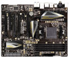
SPK Center: REAR SPK Center: FRONT LAN Top: LINE IN AUDIO CODEC CMOS BATTERY AMD 990FX Chipset PCIE1 Super I/O PCIE2 990FX Extreme9 PCIE3 PCIE4 AMD SB950 Chipset SATA3_A1_A2 SATA3_5_6 SATA3_3_4 32Mb BIOS FRONT_1394 HD_AUDIO1 1 11 PCI1 RoHS IR1 1 1 PCIE5 COM1 PLED1 1 PANEL - ASRock 990FX Extreme9 | User Manual - Page 15
Pink) USB 3.0 Ports (USB3_2_3) IEEE 1394 Port (IEEE 1394) eSATA3 Connector (ESATA1) eSATA3 Connector (ESATA2) USB 3.0 Ports (USB3_0_1) Optical SPDIF Out Port Clear CMOS Switch (CLRCBTN) PS/2 Keyboard Port (Purple) * There are two LED next to the LAN port. Please refer to the table below for the LAN - ASRock 990FX Extreme9 | User Manual - Page 16
Primary output" to use Rear Speaker, Central/Bass, and Front Speaker, or select "Realtek HDA Audio 2nd output" to use front panel audio. *** eSATA3 connector supports SATA Gen3 in cable 1M. 16 - ASRock 990FX Extreme9 | User Manual - Page 17
, peripherals, and/or components. 1. Unplug the power cord from the wall socket before touching any component. 2. To avoid damaging the motherboard components due to static electricity, NEVER place your motherboard directly on the carpet or the like. Also remember to use a grounded wrist strap - ASRock 990FX Extreme9 | User Manual - Page 18
Corner Small Triangle STEP 2 / STEP 3: STEP 4: Match The CPU Golden Triangle Push Down And Lock To The Socket Corner Small The Socket Lever Triangle 2.2 Installation of CPU Fan and Heatsink After you install the CPU into this motherboard, it is necessary to install a larger heatsink and - ASRock 990FX Extreme9 | User Manual - Page 19
modules, for optimal compatibility and reliability, it is recommended to install them either in the set of DDR3_A1 and DDR3_B1 slots, or in the set of DDR3_A2 and DDR3_B2 slots. 3. If only one memory module or three memory modules are installed in the DDR3 DIMM slots on this motherboard, it is - ASRock 990FX Extreme9 | User Manual - Page 20
matches the break on the slot. notch break notch break The DIMM only fits in one correct orientation. It will cause permanent damage to the motherboard and the DIMM if you force the DIMM into the slot at incorrect orientation. Step 3. Firmly insert the DIMM into the slot until the retaining - ASRock 990FX Extreme9 | User Manual - Page 21
slot) is used for PCI Express cards with x1 lane width cards, such as ASRock Game Blaster, Gigabit LAN card, SATA card. PCIE3 (PCIE x16 slot) is used x8 bandwidth. 4. Please connect a chassis fan to the motherboard's chassis fan connector (CHA_FAN1, CHA_FAN2 or CHA_FAN3) when using multiple graphics - ASRock 990FX Extreme9 | User Manual - Page 22
the expansion card and make necessary hardware settings for the card before you start the installation. Step 2. Remove the system unit cover (if your motherboard is already installed in a chassis). Step 3. Remove the bracket facing the slot that you intend to use. Keep the screws for later use. Step - ASRock 990FX Extreme9 | User Manual - Page 23
, 3-Way SLITM and Quad SLITM Operation Guide This motherboard supports NVIDIA® SLITM, 3-Way SLITM and Quad SLITM (Scalable Link Interface) technology that allows you to install up to three identical PCI Express x16 graphics cards. Currently, NVIDIA® SLITM technology supports Windows® XP / XP 64-bit - ASRock 990FX Extreme9 | User Manual - Page 24
Step3. Align and insert the ASRock SLI_Bridge_2S Card to the goldfingers on each graphics card. Make sure the ASRock SLI_Bridge_2S Card is firmly in place. ASRock SLI_Bridge_2S Card Step4. Connect a VGA cable or a DVI cable to the monitor connector or the DVI connector of the graphics card that is - ASRock 990FX Extreme9 | User Manual - Page 25
graphics cards will not work together properly. (Even the GPU chips version shall be the same.) Each graphics card should have two goldfingers for ASRock 3-Way SLI-2S1S Bridge Card connector. Insert one graphics card into PCIE1 slot, another graphics card to PCIE4 slot, and the other graphics card - ASRock 990FX Extreme9 | User Manual - Page 26
Installation and Setup Install the graphics card drivers to your system. After that, you can enable the MultiGraphics Processing Unit (GPU) feature in the NVIDIA® nView system tray utility. Please follow the below - ASRock 990FX Extreme9 | User Manual - Page 27
For Windows® VistaTM / VistaTM 64-bit / 7 / 7 64-bit / 8 / 8 64-bit OS: (For SLITM and Quad SLITM mode) A. Click the Start icon on your Windows taskbar. B. From the pop-up menu, select All Programs, and then click NVIDIA Corporation. C. Select NVIDIA Control Panel tab. D. Select Control Panel tab. - ASRock 990FX Extreme9 | User Manual - Page 28
For Windows® VistaTM / VistaTM 64-bit / 7 / 7 64-bit / 8 / 8 64-bit OS: (For 3-Way SLITM mode) A. Follow steps A to D on page 27. B. From the pop-up menu, select Set SLI and PhysX configuration. In Select a hardware acceleration setting for PhysX item, please select Enabled. In Select an SLI - ASRock 990FX Extreme9 | User Manual - Page 29
. Currently CrossFireXTM feature is supported with Windows® XP with Service Pack 2 / VistaTM / 7 / 8 OS. 3-way CrossFireXTM and Quad CrossFireXTM feature are supported with Windows® VistaTM / 7 / 8 OS only. Please check AMD website for AMD CrossFireXTM driver updates. 1. If a customer incorrectly - ASRock 990FX Extreme9 | User Manual - Page 30
Bridge Interconnects on the top of Radeon graphics cards. (CrossFire Bridge is provided with the graphics card you purchase, not bundled with this motherboard. Please refer to your graphics card vendor for details.) CrossFire Bridge or Step 3. Connect the DVI monitor cable to the DVI connector - ASRock 990FX Extreme9 | User Manual - Page 31
Install the identical 3-Way CrossFireXTM-ready graphics cards that are AMD certified because different types of graphics cards will not work provided with the graphics card you purchase, not bundled with this motherboard. Please refer to your graphics card vendor for details.) CrossFireTM Bridge - ASRock 990FX Extreme9 | User Manual - Page 32
to uninstall any previously installed Catalyst drivers prior to installation. Please check AMD website for ATITM driver updates. Step 3. Step 4. Step 5. Install the required drivers to your system. For Windows® XP OS: A. AMD recommends Windows® XP Service Pack 2 or higher to be installed - ASRock 990FX Extreme9 | User Manual - Page 33
technology, please check AMD website for updates and details. 2.7 Surround Display Feature This motherboard supports Surround Display upgrade. With the external add-on PCI Express VGA cards, you can easily enjoy the benefits of Surround Display feature. For the detailed instruction, please refer to - ASRock 990FX Extreme9 | User Manual - Page 34
GND IRTX IRRX ATX+5VSB Step3. Install Multi-Angle CIR Receiver to the front USB port. Step4. Boot up your system. Press or to enter BIOS Setup Utility. Make sure . Step5. Enter Windows. Execute ASRock support CD and install CIR Driver. (It is listed at the bottom of driver list.) 34 - ASRock 990FX Extreme9 | User Manual - Page 35
compatible with most of the chassis on the market. 3. The Multi-Angle CIR Receiver does not support Hot-Plug function. Please install it before you boot the system. * ASRock Smart Remote is only supported by some of ASRock motherboards. Please refer to ASRock website for the motherboard support list - ASRock 990FX Extreme9 | User Manual - Page 36
to default setup, please turn off the computer and unplug the power cord from the power supply. After waiting for 15 seconds, use a jumper cap to short pin2 and pin3 on CLRCMOS1 for 5 seconds. However, please do not clear the CMOS right after you update the BIOS. If you need to clear the CMOS when - ASRock 990FX Extreme9 | User Manual - Page 37
data cable can be connected to the SATA3 hard disk or the SATA3 connector on this motherboard. Serial ATA (SATA) Power Cable (Optional) connect to the SATA HDD power connector I/O panel, there are two USB 2.0 headers on this motherboard. Each USB 2.0 header can support two USB 2.0 ports. 37 - ASRock 990FX Extreme9 | User Manual - Page 38
, there are two USB 3.0 headers on this motherboard. Each USB 3.0 header can support two USB 3.0 ports. Infrared Module Header (5-pin supports Jack Sensing, but the panel wire on the chassis must support HDA to function correctly. Please follow the instruction in our manual and chassis manual - ASRock 990FX Extreme9 | User Manual - Page 39
B. Connect Audio_R (RIN) to OUT2_R and Audio_L (LIN) to OUT2_L. C. Connect Ground (GND) to Ground (GND). D. MIC_RET and OUT_RET are for HD audio panel only. You don't need to connect them for AC'97 audio panel. E. To activate the front mic. For Windows® XP / XP 64-bit OS: Select "Mixer". Select " - ASRock 990FX Extreme9 | User Manual - Page 40
) CPU_FAN_SPEED +12V (see p.14 No. 4) GND 1 2 3 4 Please connect the CPU fan cable to the connector and match the black wire to the ground pin. Though this motherboard provides 4-Pin CPU fan (Quiet Fan) support, the 3-Pin CPU fan still can work successfully even without the fan speed - ASRock 990FX Extreme9 | User Manual - Page 41
ATX power supply to this connector. 1 13 Though this motherboard provides 24-pin ATX power connector, 12 24 it can still work if you adopt a traditional 20-pin ATX power supply. To use the 20-pin ATX (FRONT_1394) on this motherboard. This IEEE 1394 header can support one IEEE 1394 port. 41 - ASRock 990FX Extreme9 | User Manual - Page 42
Serial port Header (9-pin COM1) (see p.14 No. 31) This COM1 header supports a serial port module. Consumer Infrared Module Header (4-pin CIR1) (see p.14 No. 27) 1 GND IRTX IRRX ATX+5VSB This header can be used to connect the remote controller receiver. 42 - ASRock 990FX Extreme9 | User Manual - Page 43
chassis screws. Step 5 Plug the Front USB 3.0 cable into the USB 3.0 header (USB3_4_5 or USB3_6_7) on the motherboard. Step 6 The Front USB 3.0 Panel is ready to use. The Installation Guide of Rear USB 3.0 Bracket Step 1 Unscrew the two screws from the Front USB 3.0 Step 2 Put the USB 3.0 cable - ASRock 990FX Extreme9 | User Manual - Page 44
2.11 Smart Switches The motherboard has three smart switches: power switch, reset switch and clear CMOS switch, allowing users to quickly turn on/off or reset the sytem clear the CMOS values. Power Switch (PWRBTN) (see p.14 No. 21) Power Power Switch is a smart switch, allowing users to - ASRock 990FX Extreme9 | User Manual - Page 45
makes troubleshooting even easier. Please see the diagrams below for reading the Dr. Debug codes. Status Code 00 0d 01 - 54 (except 0d), 5A- 60 55 61 - 91 92 - 99 A0 - A7 b0 b4 b7 d6 d7 d8 FF Description Please check if CPU is installed correctly and then clear CMOS. Problem related to memory, VGA - ASRock 990FX Extreme9 | User Manual - Page 46
2.13 Serial ATA3 (SATA3) Hard Disks Installation This motherboard adopts AMD SB950 chipset that supports Serial ATA3 (SATA3) hard disks and RAID (RAID 0, RAID 1, RAID 0+1, JBOD and RAID 5) functions. It also adopts ASMedia ASM1061 chipset that supports Serial ATA3 (SATA3) hard disks. You may install - ASRock 990FX Extreme9 | User Manual - Page 47
is installed into system properly. The latest SATA3 driver is available on our support website: www.asrock.com 4. Make sure to use the SATA power cable & data cable, which are from our motherboard package. 5. Please follow below instructions step by step to reduce the risk of HDD crash or data - ASRock 990FX Extreme9 | User Manual - Page 48
supply 1x4-pin cable. Step 2 Connect SATA data cable to the motherboard's SATA3 connector. SATA power cable 1x4-pin power connector (White) Step attention, before you process the Hot Unplug: Please do follow below instruction sequence to process the Hot Unplug, improper procedure will cause the - ASRock 990FX Extreme9 | User Manual - Page 49
Set up UEFI. A. Enter UEFI SETUP UTILITY Advanced screen Storage Configuration. B. Set the "SATA Mode" option to [RAID]. (For SATA3_1 to SATA3_6 ports.) STEP 2: Make a SATA3 Driver Diskette. (Please use an USB floppy or a floppy disk.) A. Insert the ASRock Support CD into your optical drive to boot - ASRock 990FX Extreme9 | User Manual - Page 50
path in the Support CD: .. \ RAID Installation Guide STEP 4: Install Windows® XP / XP 64-bit OS on your system. After step 1, 2, 3, you can start to install Windows® XP / XP 64-bit OS on your system. At the beginning of Windows® setup, press F6 to install a third-party RAID driver. When prompted - ASRock 990FX Extreme9 | User Manual - Page 51
on your system. At the beginning of Windows® setup, press F6 to install a third-party AHCI driver. When prompted, insert the SATA3 driver diskette containing the AMD AHCI driver. After reading the floppy disk, the driver will be presented. Select the driver to install according to the OS you install - ASRock 990FX Extreme9 | User Manual - Page 52
Technology This motherboard supports Untied Overclocking Technology, which means during overclocking, FSB enjoys better margin due to fixed PCI / PCIE buses. Before you enable Untied Overclocking function, please enter "Overclock Mode" option of UEFI setup to set the selection from [Auto] to [Manual - ASRock 990FX Extreme9 | User Manual - Page 53
UEFI SETUP UTILITY to configure your system. The UEFI chip on the motherboard stores the UEFI SETUP UTILITY. You may run the UEFI SETUP UTILITY when back on. Because the UEFI software is constantly being updated, the following UEFI setup screens and descriptions are for reference purpose only, and - ASRock 990FX Extreme9 | User Manual - Page 54
of the screen To display the General Help Screen Discard changes and exit the UEFI SETUP UTILITY Load optimal default values for all the settings Save changes and exit the UEFI SETUP UTILITY Print screen Jump to the Exit Screen or exit the current screen - ASRock 990FX Extreme9 | User Manual - Page 55
Mode Use this to select Overclock Mode. Configuration options: [Auto] and [Manual]. The default value is [Auto]. Spread Spectrum This item should always be [Auto] for better system stability. ASRock UCC ASRock UCC (Unlock CPU Core) feature simplifies AMD CPU activation. As long as a simple switch - ASRock 990FX Extreme9 | User Manual - Page 56
CPU Active Core Control feature. The configuration options depend on the CPU core you adopt. The default value is [Disabled]. AMD Turbo Core Technology This item appears only when the processor you adopt supports ] by default. If it is set to [Manual], you may adjust the value of Processor Frequency - ASRock 990FX Extreme9 | User Manual - Page 57
-Transport bus width. Configuration options: [8 Bit] and [16 Bit]. DRAM Timing Configuration DRAM Frequency If [Auto] is selected, the motherboard will detect the memory module(s) inserted and assigns appropriate frequency automatically. DRAM Timing Control DRAM Slot Use this item to view SPD data - ASRock 990FX Extreme9 | User Manual - Page 58
Load-line calibration Use this to select CPU Load-line calibration. The default value is [Auto]. ]. HT Voltage Use this to select HT Voltage. The default value is [Auto]. CPU VDDA Voltage Use this to select CPU VDDA Voltage. The default value is [Auto]. PCIE VDDA Voltage Use this to select - ASRock 990FX Extreme9 | User Manual - Page 59
3.4 Advanced Screen In this section, you may set the configurations for the following items: CPU Configuration, Nouth Bridge Configuration, South Bridge Configuration, Storage Configuration, Super IO Configuration, ACPI Configuration and USB Configuration. Setting wrong values in this section may - ASRock 990FX Extreme9 | User Manual - Page 60
to system stability or compatibility issue with some memory modules or power supplies. Please set this item to [Disable] if above issue occurs. Enhance Halt State (C1E) All processors support the Halt State (C1). The C1 state is supported through the native processor instructions HLT and MWAIT and - ASRock 990FX Extreme9 | User Manual - Page 61
3.4.2 North Bridge Configuration Primary Graphics Adapter This item will switch the PCI Bus scanning order while searching for video card. It allows you to select the type of Primary VGA in case of multiple video controllers. The default value of this feature is [PCI Express]. Configuration options: - ASRock 990FX Extreme9 | User Manual - Page 62
3.4.3 South Bridge Configuration Onboard HD Audio Select [Auto], [Enabled] or [Disabled] for the onboard HD Audio feature. If you select [Auto], the onboard HD Audio will be disabled when PCI Sound Card is plugged. Front Panel Select [Auto] or [Disabled] for the onboard HD Audio Front Panel. - ASRock 990FX Extreme9 | User Manual - Page 63
option is [AHCI Mode]. Configuration options: [AHCI Mode], [RAID Mode] and [IDE Mode]. If you set this item to RAID mode, it is suggested to install SATA ODD driver on SATA3_5 or SATA3_6 port. AMD AHCI BIOS ROM Use this item to enable or disable AMD AHCI BIOS ROM. The default value of this option is - ASRock 990FX Extreme9 | User Manual - Page 64
ASMedia SATA3 Mode This item is for SATA3_A1 and SATA3_A2 ports. Use this item to adjust the "ASMedia SATA3 Mode" feature. Configuration options: [Disabled], [IDE Mode] and [AHCI Mode]. The default value is [AHCI Mode]. SATA Boot ROM Use this to enable or disable Onboard ASMedia SATA3 Option ROM. If - ASRock 990FX Extreme9 | User Manual - Page 65
3.4.5 Super IO Configuration Serial Port Use this item to enable or disable the onboard serial port. Serial Port Address Use this item to set the address for the onboard serial port. Configuration options: [3F8h / IRQ4] and [3E8h / IRQ4]. Infrared Port Use this item to enable or disable the onboard - ASRock 990FX Extreme9 | User Manual - Page 66
the OS supports it. Check Ready Bit Use this item to enable or disable the feature Check Ready Bit. ACPI HPET table Use this item to enable or disable ACPI HPET Table. The default value is [Enabled]. Please set this option to [Enabled] if you plan to use this motherboard to submit - ASRock 990FX Extreme9 | User Manual - Page 67
USB Phy Power Down Use this item to enable the USB PHY to power down in S4/S5 state. USB Keyboard/Remote Power On Use this item to enable or disable the system to wake from S5 using USB Keyboard/Remote. USB Mouse Power On Use this item to enable or disable the system to wake from S5 using USB Mouse. - ASRock 990FX Extreme9 | User Manual - Page 68
. If you have USB compatibility issue, it is recommended to select [Disabled] to enter OS. [Auto] - Enables legacy support if USB devices are connected. [UEFI Setup Only] - USB devices are allowed to use only under UEFI setup and Windows / Linux OS. Legacy USB 3.0 Support Use this option to enable - ASRock 990FX Extreme9 | User Manual - Page 69
your current system configuration in UEFI setup. OMG (Online Management Guard) RAID driver from a support CD to your USB storage device. After copying the RAID driver to your USB storage device, please change "SATA Mode" to "RAID", then you can start installing the OS in RAID mode. UEFI Update - ASRock 990FX Extreme9 | User Manual - Page 70
searches for available UEFI firmware updates from our servers. In USA] and [China]. Dehumidifier Function Users may prevent motherboard damages due to dampness by enabling "Dehumidifier Function". Dehumidifier CPU Fan Setting Use this setting to configure CPU fan speed while "Dehumidifier" is enabled. - ASRock 990FX Extreme9 | User Manual - Page 71
Would you like to save current setting user defaults? In this option, you are allowed to load and save three user defaults according to your own requirements. 71 - ASRock 990FX Extreme9 | User Manual - Page 72
CPU temperature, motherboard temperature, CPU fan speed, chassis fan speed, and the critical voltage. CPU Fan 1 & 2 Setting This allows you to set the CPU set the chassis fan 2 speed. Confi guration options: [Full On] and [Manual]. The default is value [Full On]. Chassis Fan 3 Setting This allows you - ASRock 990FX Extreme9 | User Manual - Page 73
not boot by using an USB flash drive. [Ultra Fast] - There are a few restrictions. 1. Only supports Windows® 8 UEFI operating system. 2. You will not be able to enter BIOS Setup (Clear CMOS or run utility in Widows® to enter BIOS Setup). 3. If you are using an external graphics card, the VBIOS must - ASRock 990FX Extreme9 | User Manual - Page 74
Full Screen Logo Use this item to enable or disable OEM Logo. The default value is [Enabled]. AddOn ROM Display Use this option to adjust AddOn ROM Display. If you enable the option "Full Screen Logo" but you want to see the AddOn ROM information when the system boots, please select [Enabled]. - ASRock 990FX Extreme9 | User Manual - Page 75
3.8 Security Screen In this section, you may set or change the supervisor/user password for the system. For the user password, you may also clear it. Secure Boot Use this to enable or disable Secure Boot. The default value is [Disabled]. 75 - ASRock 990FX Extreme9 | User Manual - Page 76
UTILITY. Discard Changes and Exit When you select this option, it will pop-out the following message, "Discard changes and exit setup?" Select [OK] to exit the UEFI SETUP UTILITY without saving any changes. Discard Changes When you select this option, it will pop-out the following message, "Discard - ASRock 990FX Extreme9 | User Manual - Page 77
settings and hardware options vary, use the setup procedures in this chapter for general reference only. Refer to your OS documentation for more information. 4.2 Support CD Information The Support CD that came with the motherboard contains necessary drivers and useful utilities that enhance the - ASRock 990FX Extreme9 | User Manual - Page 78
OS on a HDD Larger Than 2TB This motherboard is adopting UEFI BIOS that allows Windows® OS to be installed on at system POST. Set AHCI Mode in UEFI Setup Utility > Advanced > Storage Configuration > SATA Mode. 3. Choose the item "UEFI:xxx" to boot in UEFI Setup Utility > Boot > Boot Option #1. ("xxx
-
 1
1 -
 2
2 -
 3
3 -
 4
4 -
 5
5 -
 6
6 -
 7
7 -
8
-
9
-
10
-
11
-
12
-
13
-
14
-
15
-
16
-
17
-
18
-
19
-
20
-
21
-
22
-
23
-
24
-
25
-
26
-
27
-
28
-
29
-
30
-
31
-
32
-
33
-
34
-
35
-
36
-
37
-
38
-
39
-
40
-
41
-
42
-
43
-
44
-
45
-
46
-
47
-
48
-
49
-
50
-
51
-
52
-
53
-
54
-
55
-
56
-
57
-
58
-
59
-
60
-
61
-
62
-
63
-
64
-
65
-
66
-
67
-
68
-
69
-
70
-
71
-
72
-
73
-
74
-
75
-
76
-
77
-
78
 |
 |

1
990FX Extreme9
User Manual
Version 1.0
Published January 2013
Copyright©2013 ASRock INC. All rights reserved.