ASRock A230GC User Manual
ASRock A230GC Manual
 |
View all ASRock A230GC manuals
Add to My Manuals
Save this manual to your list of manuals |
ASRock A230GC manual content summary:
- ASRock A230GC | User Manual - Page 1
A330GC / A230GC User Manual Version 1.0 Published May 2009 Copyright©2009 ASRock INC. All rights reserved. 1 - ASRock A230GC | User Manual - Page 2
purchaser for backup purpose, without written consent of ASRock Inc. Products and corporate names appearing in this manual may or may not be registered trademarks or copyrights USA ONLY The Lithium battery adopted on this motherboard contains Perchlorate, a toxic substance controlled in Perchlorate - ASRock A230GC | User Manual - Page 3
Contents 1 Introduction 5 1.1 Package Contents 5 1.2 Specifications 6 1.3 Motherboard Layout 9 1.4 I/O Panel 10 2 Installation 11 2.1 Screw SATAII Hard Disk Setup Guide 19 2.9 Serial ATA (SATA) / Serial ATAII (SATAII) Hard Disks Installation 20 2.10 Driver Installation Guide 20 2.11 Untied - ASRock A230GC | User Manual - Page 4
4 Software Support 39 4.1 Install Operating System 39 4.2 Support CD Information 39 4.2.1 Running Support CD 39 4.2.2 Drivers Menu 39 4.2.3 Utilities Menu 39 4.2.4 Contact Information 39 4 - ASRock A230GC | User Manual - Page 5
Package Contents ASRock A330GC / A230GC Motherboard (Mini-ITX Form Factor: 6.7-in x 6.7-in, 17.0 cm x 17.0 cm) One Bundled Intel® Dual-Core AtomTM Processor 330 (A330GC) One Bundled Intel® AtomTM Processor 230 (A230GC) ASRock A330GC / A230GC Quick Installation Guide ASRock A330GC / A230GC Support CD - ASRock A230GC | User Manual - Page 6
A330GC) - Intel® AtomTM Processor 230 (1.6 GHz) (A230GC) - Supports FSB533 MHz - Supports Hyper-Threading Technology (see CAUTION 1) - Supports Untied Overclocking Technology (see CAUTION 2) - Supports x DDR2 DIMM slots - Supports DDR2 533 non-ECC, un-buffered memory - Max. capacity of system memory: - ASRock A230GC | User Manual - Page 7
and Play" - ACPI 1.1 Compliance Wake Up Events - Supports jumperfree - AMBIOS 2.3.1 Support - CPU, VCCM, NB, VTT Voltage Multi-adjustment - Supports Smart BIOS Support CD - Drivers, Utilities, AntiVirus Software (Trial Version) Unique Feature - ASRock OC Tuner (see CAUTION 8) - Instant Boot - ASRock A230GC | User Manual - Page 8
This motherboard supports Dual Channel Memory Technology. Before you implement Dual Channel Memory Technology, make sure to read the installation guide of during the POST or press key to BIOS setup menu to access ASRock Instant Flash. Just launch this tool and save the new BIOS file to your - ASRock A230GC | User Manual - Page 9
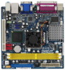
1.3 Motherboard Layout PS2 Keyboard 1 2 3 45 6 17.0cm (6.7 in) USB 2.0 T: USB2 B: USB3 CPU_FAN1 Super IO 7 CHA_FAN1 PS2 Mouse Gigabit LAN Dual Channel PARALLEL PORT 17.0cm (6.7 in) - ASRock A230GC | User Manual - Page 10
1.4 I/O Panel 1 2 11 10 9 1 USB 2.0 Ports (USB23) 2 Parallel Port 3 VGA Port 4 RJ-45 Port 5 Line In (Light Blue) 6 Line Out (Lime) 3 4 5 6 7 8 7 Microphone (Pink) 8 USB 2.0 Ports (USB01) 9 COM Port 10 PS/2 Mouse Port (Green) 11 PS/2 Keyboard Port (Purple) * To enable Multi-Streaming - ASRock A230GC | User Manual - Page 11
Installation A330GC / A230GC is a Mini-IXT form factor (6.7" x 6.7", 17.0 x 17.0 cm) motherboard. Before you install the motherboard, study the configuration of your chassis to ensure that the motherboard fits into it. Make sure to unplug the power cord before installing or removing the motherboard - ASRock A230GC | User Manual - Page 12
9, No. 2). For proper installation, please kindly refer to the instruction manual of your CPU fan. Step 1. Place the CPU fan onto the CPU heatsink. Ensure fan cables are oriented on side closest to the CPU fan connector on the motherboard (CPU_FAN1, see page 9, No. 2). Step 2. Rotate the CPU fan - ASRock A230GC | User Manual - Page 13
2.4 Installation of Memory Modules (DIMM) A330GC / A230GC motherboard provides two 240-pin DDR2 (Double Data Rate 2) DIMM slots, and supports Dual Channel Memory Technology. For dual channel configuration, you always need to install two identical (the same brand, speed, size and chip-type) memory - ASRock A230GC | User Manual - Page 14
2.5 Expansion Slot (PCI Slot) There is 1 PCI slot on this motherboard. PCI slot: PCI slot is used to install expansion cards that have the 32-bit PCI interface. Installing an expansion card Step 1. Before installing the - ASRock A230GC | User Manual - Page 15
2.6 Jumpers Setup The illustration shows how jumpers are setup. When the jumper cap is placed on pins, the jumper is "Short". If no jumper cap is placed on pins, the jumper is "Open". The illustration shows a 3-pin jumper whose pin1 and pin2 are "Short" when jumper cap is placed on these 2 - ASRock A230GC | User Manual - Page 16
39-pin IDE1, see p.9 No. 8) PIN1 IDE1 connect the blue end connect the black end to the motherboard to the IDE devices 80-conductor ATA 66/100 cable Note: Please refer to the instruction of your IDE device vendor for the details. Serial ATAII Connectors (SATAII_1: see p.9, No. 14) (SATAII_2 - ASRock A230GC | User Manual - Page 17
allows convenient connection and control of audio devices. 1. High Definition Audio supports Jack Sensing, but the panel wire on the chassis must support HDA to function correctly. Please follow the instruction in our manual and chassis manual to install your system. 2. If you use AC'97 audio - ASRock A230GC | User Manual - Page 18
FAN_SPEED_CONTROL Please connect a CPU fan cable to this connector and match the black wire to the ground pin. Though this motherboard provides 4-Pin CPU fan (Quiet Fan) support, the 3-Pin CPU fan still can work successfully even without the fan speed control function. If you plan to connect - ASRock A230GC | User Manual - Page 19
guide. Some default setting of SATAII hard disks may not be at SATAII mode, which operate with the best performance. In order to enable SATAII function, please follow the below instruction website for details: http://www.hitachigst.com/hdd/support/download.htm The above examples are just for your - ASRock A230GC | User Manual - Page 20
Connect one end of the SATA data cable to the motherboard's SATAII connector. STEP 4: Connect the other end of the SATA data cable to the SATA / SATAII hard disk. 2.10 Driver Installation Guide To install the drivers to your system, please insert the support CD to your optical drive first. Then, the - ASRock A230GC | User Manual - Page 21
Chapter 3 BIOS SETUP UTILITY 3.1 Introduction This section explains how to use the BIOS SETUP UTILITY to configure your system. The BIOS FWH chip on the motherboard stores the BIOS SETUP UTILITY. You may run the BIOS SETUP UTILITY when you start up the computer. Please press during the Power-On - ASRock A230GC | User Manual - Page 22
or exit the current screen 3.2 Main Screen When you enter the BIOS SETUP UTILITY, the Main screen will appear and display the system overview. A330GC BIOS SETUP UTILITY Main Smart Advanced H/W Monitor Boot Security Exit System Overview System Time System Date [14:00:09] [Wed 05/13/2009] BIOS - ASRock A230GC | User Manual - Page 23
System Time System Date [14:00:09] [Wed 05/13/2009] BIOS Version : A230GC P1.00 Processor Type : Intel (R) Atom (TM) CPU 230 @ 1.60GHz (64bit Overclocking Load Optimized CPU OC Setting [Press Enter] BIOS Update Utility ASRock Instant Flash Exit system setup after saving the changes. F10 key can - ASRock A230GC | User Manual - Page 24
GHz], [1.9 GHz], [2.0 GHz] and [2.1 GHz]. Please note that overclocing may cause damage to your CPU and motherboard. It should be done at your own risk and expense. ASRock Instant Flash ASRock Instant Flash is a BIOS flash utility embedded in Flash ROM. This convenient BIOS update tool allows you to - ASRock A230GC | User Manual - Page 25
3.4 Advanced Screen In this section, you may set the configurations for the following items: CPU Configuration, Chipset Configuration, ACPI Configuration, IDE Configuration, PCIPnP Configuration, SuperIO Configuration, and USB Configuration. BIOS SETUP UTILITY Main Smart Advanced H/W Monitor Boot - ASRock A230GC | User Manual - Page 26
is a read-only item, which displays the ratio actual value of this motherboard. CPU Thermal Throttling You may select [Enabled] to enable P4 CPU a computer system with an Intel Pentium® 4 processor that supports Hyper-Threading technology and an operating system that includes optimization for - ASRock A230GC | User Manual - Page 27
Configuration options: [Auto] and [Manual]. Primary Graphics Adapter This item shows architecture that offers breakthrough performance for the motherboard through efficient memory utilization. In Fixed mode core. In DVMT mode, the graphics driver allocates memory as needed for running graphics - ASRock A230GC | User Manual - Page 28
DVMT/FIXED Memory You are allowed to adjust the shared memory size in this item if you set DVMT Mode Select as [DVMT Mode]. Configuration options: [64MB], [128MB] and [Maximum DVMT]. Onboard GPU clock Use this item to adjust onboard GPU clock. Configuration options: [Normal] and [Overclock]. The - ASRock A230GC | User Manual - Page 29
detect or disable the Suspend-to-RAM feature. Select [Auto] will enable this feature if the system supports it. Restore on AC/Power Loss This allows you to set the power state after an unexpected AC option to [Enabled] if you plan to use this motherboard to submit Windows® VistaTM certification. 29 - ASRock A230GC | User Manual - Page 30
use the "Primary IDE Master" as the example in the following instruction. BIOS SETUP UTILITY Advanced Primary IDE Master Device Vendor Size LBA Mode Data Transfer :Hard Disk :ST340014A :40.0 GB :Supported :16Sectors :4 :MultiWord DMA-2 :Ultra DMA-5 :Supported [Auto] [Auto] [Auto] [Auto] [Auto] - ASRock A230GC | User Manual - Page 31
After selecting the hard disk information into BIOS, use a disk utility, such as FDISK, to partition and format the new IDE hard disk drives. This is necessary so that you can write or read data from the hard disk. Make sure to set the partition of the Primary IDE hard disk drives to active. [CD/DVD - ASRock A230GC | User Manual - Page 32
3.4.5 PCIPnP Configuration BIOS SETUP UTILITY Advanced Advanced PCI / PnP Settings PCI Latency Timer PCI IDE BusMaster [32] [Enabled] Value in units of PCI clocks for PCI device latency timer register. +F1 F9 F10 ESC Select Screen Select Item Change Option General Help Load Defaults Save and - ASRock A230GC | User Manual - Page 33
3.4.6 Super IO Configuration BIOS SETUP UTILITY Advanced Configure Super IO Chipset Serial Port Address Parallel Port Address Parallel Port Mode EPP Version ECP Mode DMA Channel Parallel Port IRQ [3F8 / IRQ4] [378] [ECP + EPP] [1.9] [DMA3] [IRQ7] Allow BIOS to Select Serial Port Base Addresses. - ASRock A230GC | User Manual - Page 34
]. The default value is [Enabled]. Please refer to below descriptions for the details of these four options: [Enabled] - Enables support for legacy USB. [Auto] - Enables legacy support if USB devices are connected. [Disabled] - USB devices are not allowed to use under legacy OS and BIOS setup when - ASRock A230GC | User Manual - Page 35
In this section, it allows you to monitor the status of the hardware on your system, including the parameters of the CPU temperature, motherboard temperature, CPU fan speed, chassis fan speed, and the critical voltage. BIOS SETUP UTILITY Main Smart Advanced H/W Monitor Boot Security Exit Hardware - ASRock A230GC | User Manual - Page 36
3.6 Boot Screen In this section, it will display the available devices on your system for you to configure the boot settings and the boot priority. BIOS SETUP UTILITY Main Smart Advanced H/W Monitor Boot Security Exit Boot Settings Boot Settings Configuration Configure Settings during System - ASRock A230GC | User Manual - Page 37
3.7 Security Screen In this section, you may set or change the supervisor/user password for the system. For the user password, you may also clear it. BIOS SETUP UTILITY Main Smart Advanced H/W Monitor Boot Security Exit Security Settings Supervisor Password : Not Installed User Password : Not - ASRock A230GC | User Manual - Page 38
3.8 Exit Screen BIOS SETUP UTILITY Main Smart Advanced H/W Monitor Boot Security Exit Exit Options Save Changes and Exit Discard Changes and Exit Discard Changes Would you like to save current setting user defaults ? Save 1st User Defaults Load 1st User Defaults Save 2nd User Defaults Load 2nd - ASRock A230GC | User Manual - Page 39
install the necessary drivers to activate the devices. 4.2.3 Utilities Menu The Utilities Menu shows the applications software that the motherboard supports. Click on a specific item then follow the installation wizard to install it. 4.2.4 Contact Information If you need to contact ASRock or want to
-
 1
1 -
 2
2 -
 3
3 -
 4
4 -
 5
5 -
 6
6 -
 7
7 -
8
-
9
-
10
-
11
-
12
-
13
-
14
-
15
-
16
-
17
-
18
-
19
-
20
-
21
-
22
-
23
-
24
-
25
-
26
-
27
-
28
-
29
-
30
-
31
-
32
-
33
-
34
-
35
-
36
-
37
-
38
-
39
 |
 |

1
A330GC /
A230GC
User Manual
Version 1.0
Published May 2009
Copyright©2009 ASRock INC. All rights reserved.