ASRock A520M Pro4 User Manual
ASRock A520M Pro4 Manual
 |
View all ASRock A520M Pro4 manuals
Add to My Manuals
Save this manual to your list of manuals |
ASRock A520M Pro4 manual content summary:
- ASRock A520M Pro4 | User Manual - Page 1
- ASRock A520M Pro4 | User Manual - Page 2
documentation are furnished for informational use only and subject to change without notice, and should not be constructed as a commitment by ASRock. ASRock assumes no responsibility for any errors or omissions that may appear in this documentation. With respect to the contents of this documentation - ASRock A520M Pro4 | User Manual - Page 3
if the goods fail to be of acceptable quality and the failure does not amount to a major failure. If you require assistance please call ASRock Tel : +886-2-28965588 ext.123 (Standard International call charges apply) The terms HDMI® and HDMI High-Definition Multimedia Interface, and the HDMI logo - ASRock A520M Pro4 | User Manual - Page 4
2_SSD (NGFF) Module Installation Guide (M2_2) 37 2.10 M.2 WiFi/BT Module Installation Guide (M2_3) 40 Chapter 3 Software and Utilities Operation 42 3.1 Installing Drivers 42 3.2 ASRock Motherboard Utility (A-Tuning) 43 3.2.1 Installing ASRock Motherboard Utility (A-Tuning) 43 3.2.2 Using - ASRock A520M Pro4 | User Manual - Page 5
3.3.1 UI Overview 46 3.3.2 Apps 47 3.3.3 BIOS & Drivers 50 3.3.4 Setting 51 3.4 Nahimic Audio 52 3.5 ASRock Polychrome SYNC 53 Chapter 4 UEFI SETUP UTILITY 56 4.1 Introduction 56 4.1.1 UEFI Menu Bar 56 4.1.2 Navigation Keys 57 4.2 Main Screen 58 4.3 OC Tweaker Screen 59 4.4 - ASRock A520M Pro4 | User Manual - Page 6
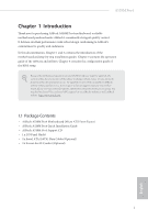
latest VGA cards and CPU support list on ASRock's website as well. ASRock website http://www.asrock.com. 1.1 Package Contents • ASRock A520M Pro4 Motherboard (Micro ATX Form Factor) • ASRock A520M Pro4 Quick Installation Guide • ASRock A520M Pro4 Support CD • 1 x I/O Panel Shield • 2 x Serial ATA - ASRock A520M Pro4 | User Manual - Page 7
Platform CPU • Micro ATX Form Factor • Solid Capacitor design • 2oz Copper PCB • Supports 3rd Gen AMD Support List on ASRock's website for more information. (http://www.asrock.com/) * Please refer to page 22 for DDR4 UDIMM maximum frequency support. • Max. capacity of system memory: 128GB • Supports - ASRock A520M Pro4 | User Manual - Page 8
A520M Pro4 Graphics Audio • Integrated AMD RadeonTM Vega Series Graphics in Ryzen Series APU* * Actual support may vary by CPU • DirectX 12, Pixel Shader 5.0 • Shared memory default 2GB. Max Shared memory supports up to 16GB. * The Max shared memory 16GB requires 32GB system memory installed. • - ASRock A520M Pro4 | User Manual - Page 9
Supports Wake-On-LAN • Supports Lightning/ESD Protection • Supports Energy Efficient Ethernet 802.3az • Supports • 4 x SATA3 6.0 Gb/s Connectors, support RAID (RAID 0, RAID 1 and RAID 10 supports M Key type 2280 M.2 PCI Express module up to Gen3 x4 (32 Gb/s)** • 1 x M.2 Socket (M2_2), supports - ASRock A520M Pro4 | User Manual - Page 10
A520M Pro4 Connector • 1 x COM Port Header • 1 x SPI TPM Header • 1 x Power LED and Speaker Header • 2 x RGB LED Headers * Support in total up to 12V/3A, 36W LED Strip • 2 x Addressable LED Headers * Support in total up to 5V/3A, 15W LED Strip • 1 x CPU Fan Connector (4-pin) * The CPU Fan - ASRock A520M Pro4 | User Manual - Page 11
• FCC, CE • ErP/EuP ready (ErP/EuP ready power supply is required) * For detailed product information, please visit our website: http://www.asrock.com Please realize that there is a certain risk involved with overclocking, including adjusting the setting in the BIOS, applying Untied Overclocking - ASRock A520M Pro4 | User Manual - Page 12
USB31_TA_1 B: USB31_TC_1 USB 3.2 Gen1 T: USB1 B: USB2 RJ-45 LAN USB 3.2 Gen1 T: USB3 B: USB4 CHA_FAN1/WP RoHS CPU_FAN2/WP CPU_FAN1 RGB_LED1 1 1 ADDR_LED1 A520M Pro4 ATXPWR1 DDR4_A1 (64 bit, 288-pin module) DDR4_A2 (64 bit, 288-pin module) DDR4_B1 (64 bit, 288-pin module) DDR4_B2 (64 bit, 288 - ASRock A520M Pro4 | User Manual - Page 13
DIMM Slots (DDR4_A1, DDR4_B1) 5 2 x 288-pin DDR4 DIMM Slots (DDR4_A2, DDR4_B2) 6 RGB LED Header (RGB_LED1) 7 Addressable LED Header (ADDR_LED1) 8 ATX Power Connector (ATXPWR1) 9 USB 3.2 Gen1 Header (F_USB3_1_2) 10 SATA3 Connector (SATA3_2) 11 SATA3 Connector (SATA3_1) 12 SATA3 Connector (SATA3_4 - ASRock A520M Pro4 | User Manual - Page 14
1.4 I/O Panel 1 2 A520M Pro4 4 3 5 14 13 12 11 9 8 10 7 6 No. Description 1 D-Sub Port 2 USB 2.0 Ports (USB_12)* 3 LAN RJ-45 Port** 4 Line In (Light Blue)*** 5 Front Speaker (Lime)*** 6 Microphone (Pink)*** 7 - ASRock A520M Pro4 | User Manual - Page 15
*** Function of the Audio Ports in 7.1-channel Configuration: Port Light Blue (Rear panel) Lime (Rear panel) Pink (Rear panel) Lime (Front panel) Function Rear Speaker Out Front Speaker Out Central /Subwoofer Speaker Out Side Speaker Out English 10 - ASRock A520M Pro4 | User Manual - Page 16
A520M Pro4 Chapter 2 Installation This is a Micro ATX form factor motherboard. Before you install the motherboard, study the configuration of your chassis to ensure that the motherboard fits into it. Pre-installation Precautions - ASRock A520M Pro4 | User Manual - Page 17
2.1 Installing the CPU Unplug all power cables before installing the CPU. 1 2 12 English - ASRock A520M Pro4 | User Manual - Page 18
A520M Pro4 3 13 English - ASRock A520M Pro4 | User Manual - Page 19
2.2 Installing the CPU Fan and Heatsink After you install the CPU into this motherboard, it is necessary to install a larger heatsink and cooling fan to dissipate heat. You also need to spray thermal grease between the CPU and the heatsink to improve heat dissipation. Make sure that the CPU and the - ASRock A520M Pro4 | User Manual - Page 20
A520M Pro4 3 4 CPU_FAN1 15 English - ASRock A520M Pro4 | User Manual - Page 21
Installing the AM4 Box Cooler SR2 1 2 16 English - ASRock A520M Pro4 | User Manual - Page 22
A520M Pro4 3 17 English - ASRock A520M Pro4 | User Manual - Page 23
4 CPU_FAN1 *The diagrams shown here are for reference only. The headers might be in a different position on your motherboard. 18 English - ASRock A520M Pro4 | User Manual - Page 24
Installing the AM4 Box Cooler SR3 1 A520M Pro4 2 19 English - ASRock A520M Pro4 | User Manual - Page 25
3 4 20 English - ASRock A520M Pro4 | User Manual - Page 26
A520M Pro4 5 CPU_FAN1 6 CPU_FAN1 +12V RGB_LED2 *The diagrams shown here are for reference only. The headers might be in a different position on your motherboard. 21 English - ASRock A520M Pro4 | User Manual - Page 27
you install the memory modules on DDR4_A2 and DDR4_B2 first for better DRAM compatibility on 2 DIMMs configuration. AMD non-XMP Memory Frequency Support Ryzen Series CPUs (Matisse): UDIMM Memory Slot A1 A2 B1 B2 Frequency (Mhz) - SR - - 3200 - DR - - 3200 - SR - SR 3200 - DR - ASRock A520M Pro4 | User Manual - Page 28
SR/DR 2667 SR: Single rank DIMM, 1Rx4 or 1Rx8 on DIMM module label DR: Dual rank DIMM, 2Rx4 or 2Rx8 on DIMM module label A520M Pro4 English 23 - ASRock A520M Pro4 | User Manual - Page 29
The DIMM only fits in one correct orientation. It will cause permanent damage to the motherboard and the DIMM if you force the DIMM into the slot at incorrect orientation. 1 2 3 24 English - ASRock A520M Pro4 | User Manual - Page 30
A520M Pro4 2.4 Expansion Slots (PCI Express Slots) There are 2 PCI Express slots on the motherboard. Before installing an expansion card, please make sure that the power supply - ASRock A520M Pro4 | User Manual - Page 31
2.5 Jumpers Setup The illustration shows how jumpers are setup. When the jumper cap is placed on the pins, the jumper is "Short". If no jumper cap is placed on the pins, the jumper is "Open". Clear CMOS Jumper (CLRCMOS1) (see p.7, No. 23) 2-pin Jumper Short: Clear CMOS Open: Default CLRCMOS1 - ASRock A520M Pro4 | User Manual - Page 32
A520M Pro4 2.6 Onboard Headers and Connectors Onboard headers and connectors are NOT jumpers. Do NOT place jumper caps over these headers and connectors. Placing jumper caps over - ASRock A520M Pro4 | User Manual - Page 33
No. 10) Right Angle: (SATA3_3: see p.7, No. 12) (Lower) (SATA3_4: see p.7, No. 12) (Upper) SATA3_4 SATA3_1 SATA3_3 SATA3_2 These four SATA3 connectors support SATA data cables for internal storage devices with up to 6.0 Gb/s data transfer rate. * M2_2 and SATA3_3_4 share lanes. If either one of - ASRock A520M Pro4 | User Manual - Page 34
A520M Pro4 (19-pin F_USB3_3_4) (see p.7, No. 15) IntA_P_D+ IntA_P_DGND IntA_P_SSTX+ IntA_P_SSTXGND High Definition Audio supports Jack Sensing, but the panel wire on the chassis must support HDA to function correctly. Please follow the instructions in our manual and chassis manual to install your - ASRock A520M Pro4 | User Manual - Page 35
1 2 34 CPU Fan Connector (4-pin CPU_FAN1) (see p.7, No. 2) CPU Water Pump Fan Connector (4-pin CPU_FAN2/WP) (see p.7, No. 3) ATX Power Connector (24-pin ATXPWR1) (see p.7, No. 8) 4 3 21 GND FAN_VOLTAGE CPU_FAN_SPEED FAN_SPEED_CONTROL 4 3 21 GND FAN_VOLTAGE CPU_FAN_SPEED FAN_SPEED_CONTROL 12 24 - ASRock A520M Pro4 | User Manual - Page 36
A520M Pro4 ATX 12V Power 8 5 Connector (8-pin ATX12V1) 4 1 (see p.7, No. 1) Serial Port Header (9-pin COM1) (see p.7, No. 24) RRXD1 DDTR#1 DDSR#1 CCTS#1 1 RRI#1 RRTS#1 GND TTXD1 DDCD#1 This motherboard provides an 8-pin ATX 12V power connector. To use a 4-pin ATX connector supports SPI - ASRock A520M Pro4 | User Manual - Page 37
: Never install the RGB LED cable in the wrong orientation; otherwise, the cable may be damaged. *Please refer to page 53 for further instructions on these two headers. 1 VOUT DO_ADDR GND 1 GND DO_ADDR VOUT These two Addressable headers are used to connect Addressable LED extension cable which - ASRock A520M Pro4 | User Manual - Page 38
A520M Pro4 2.7 Post Status Checker Post Status Checker (PSC) diagnoses the computer when users power on the machine. It emits a red light to indicate whether the CPU, memory, VGA or storage is dysfunctional. The lights go off if the four mentioned above are functioning normally. 33 English - ASRock A520M Pro4 | User Manual - Page 39
2.8 M.2_SSD (NGFF) Module Installation Guide (M2_1) The M.2, also known as the Next Generation Form Factor (NGFF), is a small size and versatile card edge connector that aims to replace mPCIe and mSATA. The Ultra M.2 Socket (M2_1) supports M Key type 2280 M.2 PCI Express module up to Gen3x4 (32 Gb - ASRock A520M Pro4 | User Manual - Page 40
A520M Pro4 1 Step 3 1 2 Before installing a M.2 (NGFF) SSD module, please loosen the screws to remove the M.2 heatsink. *Please remove the protective films on the bottom side of the M.2 - ASRock A520M Pro4 | User Manual - Page 41
M.2_SSD (NGFF) Module Support List (M2_1) Vendor ADATA ADATA ADATA ADATA ADATA Apacer Corsair Intel Intel WDS256G1X0C-00ENX0 (NVME) WDS512G1X0C-00ENX0 (NVME) For the latest updates of M.2_SSD (NFGG) module support list, please visit our website for details: http://www.asrock.com English 36 - ASRock A520M Pro4 | User Manual - Page 42
A520M Pro4 2.9 M.2_SSD (NGFF) Module Installation Guide (M2_2) The M.2, also known as the Next Generation Form Factor (NGFF), is a small size and versatile card edge connector that aims to replace mPCIe and mSATA. The M.2 Socket (M2_2) supports M Key type 2280 M.2 SATA3 6.0 Gb/s module and M.2 PCI - ASRock A520M Pro4 | User Manual - Page 43
Step 3 Align and gently insert the M.2 (NGFF) SSD module into the M.2 slot. Please be aware that the M.2 (NGFF) SSD module only fits in one orientation. A A 20o NUT2 NUT1 Step 4 Tighten the screw with a screwdriver to secure the module into place. Please do not overtighten the screw as this - ASRock A520M Pro4 | User Manual - Page 44
A520M Pro4 M.2_SSD (NGFF) Module Support List (M2_2) Vendor ADATA ADATA ADATA ADATA ADATA Crucial Crucial Intel Kingston Plextor -00AS40 WDS240G1G0B-00RC30 For the latest updates of M.2_SSD (NFGG) module support list, please visit our website for details: http://www.asrock.com English 39 - ASRock A520M Pro4 | User Manual - Page 45
WiFi/BT Module Installation Guide (M2_3) The M.2, also known as the Next Generation Form Factor (NGFF), is a small size and versatile card edge connector that aims to replace mPCIe and mSATA. The M.2 Socket (Key E) supports type 2230 WiFi/BT module. * The M.2 socket does not support SATA M.2 SSDs - ASRock A520M Pro4 | User Manual - Page 46
A520M Pro4 Step 4 Tighten the screw with a screwdriver to secure the module into place. Please do not overtighten the screw as this might damage the module. A 41 English - ASRock A520M Pro4 | User Manual - Page 47
CD that comes with the motherboard contains necessary drivers and useful utilities that enhance the motherboard's features. Running The Support CD To begin using the support CD, insert the CD into your CD-ROM drive. The CD automatically displays the Main Menu if "AUTORUN" is enabled in your computer - ASRock A520M Pro4 | User Manual - Page 48
A520M Pro4 3.2 ASRock Motherboard Utility (A-Tuning) ASRock Motherboard Utility (A-Tuning) is ASRock's multi purpose software suite with a new interface, more new features and improved utilities. 3.2.1 Installing ASRock Motherboard Utility (A-Tuning) ASRock Motherboard Utility (A-Tuning) can be - ASRock A520M Pro4 | User Manual - Page 49
OC Tweaker Configurations for overclocking the system. System Info View information about the system. *The System Browser tab may not appear for certain models. 44 English - ASRock A520M Pro4 | User Manual - Page 50
A520M Pro4 FAN-Tastic Tuning Configure up to five different fan speeds using the graph. The fans will automatically shift to the next speed level when the assigned temperature is met. Settings Configure ASRock ASRock Motherboard Utility (A-Tuning). Click to select "Auto run at Windows Startup" if - ASRock A520M Pro4 | User Manual - Page 51
Live Update & APP Shop is an online store for purchasing and downloading software applications for your ASRock computer. You can quickly and easily install various apps and support utilities. With ASRock Live Update & APP Shop, you can optimize your system and keep your motherboard up to date simply - ASRock A520M Pro4 | User Manual - Page 52
A520M Pro4 3.3.2 Apps When the "Apps" tab is selected, you will see all the available apps on up and down to see more apps listed. You can check the price of the app and whether you have already intalled it or not. - The red icon displays the price or "Free" if the app is free of charge. - The - ASRock A520M Pro4 | User Manual - Page 53
Step 3 If you want to install the app, click on the red icon to start downloading. Step 4 When installation completes, you can find the green "Installed" icon appears on the upper right corner. English To uninstall it, simply click on the trash can icon . *The trash icon may not appear for - ASRock A520M Pro4 | User Manual - Page 54
A520M Pro4 Upgrading an App You can only upgrade the apps you have already installed. When there is an available new version for your app, you will - ASRock A520M Pro4 | User Manual - Page 55
3.3.3 BIOS & Drivers Installing BIOS or Drivers When the "BIOS & Drivers" tab is selected, you will see a list of recommended or critical updates for the BIOS or drivers. Please update them all soon. Step 1 Please check the item information before update. Click on Step 2 to see more details. - ASRock A520M Pro4 | User Manual - Page 56
A520M Pro4 3.3.4 Setting In the "Setting" page, you can change the language, select the server location, and determine if you want to automatically run the ASRock Live Update & APP Shop on Windows startup. 51 English - ASRock A520M Pro4 | User Manual - Page 57
3.4 Nahimic Audio Nahimic audio software provides an incredible high definition sound technology which boosts the audio and voice performance of your system. Nahimic Audio interface is composed of four tabs: Audio, Microphone, Sound Tracker and Settings. There are four functions in Nahimic audio : - ASRock A520M Pro4 | User Manual - Page 58
A520M Pro4 3.5 ASRock Polychrome SYNC ASRock Polychrome SYNC is a lighting control utility specifically designed for the RGB LED strips do not come with the package. 2. The RGB LED header supports standard 5050 RGB LED strip (12V/G/R/B), with a maximum power rating of 3A (12V) and length within 2 - ASRock A520M Pro4 | User Manual - Page 59
A520M Pro4 Connecting the Addressable RGB LED Strip Connect your Addressable RGB LED strips to the note that the RGB LED strips do not come with the package. 2. The RGB LED header supports WS2812B addressable RGB LED strip (5V/Data/ GND), with a maximum power rating of 3A (5V) and length within - ASRock A520M Pro4 | User Manual - Page 60
A520M Pro4 ASRock Polychrome SYNC Utility Now you can adjust the RGB LED color through the ASRock Polychrome SYNC Utility. Download this utility from the ASRock Live Update & APP Shop and start coloring your PC style your way! Drag the tab to customize your preference. Toggle on/off the RGB LED - ASRock A520M Pro4 | User Manual - Page 61
Chapter 4 UEFI SETUP UTILITY 4.1 Introduction This section explains how to use the UEFI SETUP UTILITY to configure your system. You may run the UEFI SETUP UTILITY by pressing or right after you power on the computer, otherwise, the Power-On-Self-Test (POST) will continue with its test - ASRock A520M Pro4 | User Manual - Page 62
A520M Pro4 4.1.2 Navigation Keys Use < > key or < > key to choose among the selections on the menu bar, and use < > key or < > key to move the cursor up - ASRock A520M Pro4 | User Manual - Page 63
4.2 Main Screen When you enter the UEFI SETUP UTILITY, the Main screen will appear and display the system overview. 58 English - ASRock A520M Pro4 | User Manual - Page 64
. A520M Pro4 Because the UEFI software is constantly being updated, the following UEFI setup screens and descriptions are for reference purpose only, and they may not exactly match what you see on your screen. SoC/Uncore OC Voltage(VID) Specify the SoC/Uncore voltage (VDD_SOC) in mV to support - ASRock A520M Pro4 | User Manual - Page 65
Configure the voltage for the DRAM Voltage. Infinity Fabric Frequency and Dividers AMD Overclocking Setup Set Infinity Fabric frequency (FCLK). Auto: FCLK = MCLK. Manual: FCLK must be less than or equal to MCLK for best performance in most cases. Latency penalties are incurred if FCLK and MCLK are - ASRock A520M Pro4 | User Manual - Page 66
VPPM Configure the voltage for the VPPM. CPU VDD 1.8 Voltage Configure the voltage for the CPU VDD 1.8. A520M Pro4 English 61 - ASRock A520M Pro4 | User Manual - Page 67
UEFI setup utility. Full HD UEFI When [Auto] is selected, the resolution will be set to 1920 x 1080 if the monitor supports Full HD resolution. If the monitor does not support Full HD resolution, then the resolution will be set to 1024 x 768. When [Disable] is selected, the resolution will be set - ASRock A520M Pro4 | User Manual - Page 68
4.4.1 CPU Configuration A520M Pro4 PSS Support Use this to enable or disable the generation of ACPI_PPC, _PSS, and , a power cycle is needed after selecting [Auto]. Warning: S3 is not supported on systems where SMT is disabled. AMD fTPM Switch Use this to enable or disable AMD CPU fTPM. 63 English - ASRock A520M Pro4 | User Manual - Page 69
Onboard LED Default Restore the onboard LED default value. RGB LED On/Off ASRock Polychrome SYNC allows you to adjust the RGB LED color to your liking. SR-IOV Support Enable/disable the SR-IOV (Single Root IO Virtualization Support) if the system has SR-IOV capable PCIe devices. Gnb Hd Audio Enable - ASRock A520M Pro4 | User Manual - Page 70
A520M Pro4 Restore on AC/Power Loss Select the power state after a power failure. If [Power Off] is selected, the power will remain off when the power - ASRock A520M Pro4 | User Manual - Page 71
4.4.3 Storage Configuration SATA Mode AHCI: Supports new features that improve performance. RAID: Combine multiple disk drives into a logical unit. SATA Hot Plug Enable/disable the SATA Hot Plug function. 66 English - ASRock A520M Pro4 | User Manual - Page 72
A520M Pro4 Suspend to RAM It is recommended to select auto for ACPI S3 power saving. Deep Sleep Configure deep sleep mode for power saving when the computer is shut down. We recommend disabling Deep Sleep for better system compatibility and stability. PS/2 Keyboard S4/S5 Wakeup Support - ASRock A520M Pro4 | User Manual - Page 73
4.4.5 Super IO Configuration Serial Port Enable or disable the Serial port. Serial Port Address Select the address of the Serial port. 68 English - ASRock A520M Pro4 | User Manual - Page 74
4.4.6 Trusted Computing A520M Pro4 Security Device Support Enable or disable BIOS support for security device. English 69 - ASRock A520M Pro4 | User Manual - Page 75
4.4.7 AMD PBS The AMD PBS menu accesses AMD specific features. 70 English - ASRock A520M Pro4 | User Manual - Page 76
4.4.8 AMD CBS A520M Pro4 The AMD CBS menu accesses AMD specific features. English 71 - ASRock A520M Pro4 | User Manual - Page 77
SATA mode to RAID, then you can start installing the operating system in RAID mode. SSD Secure Erase Tool All the SSD's listed that supports Secure Erase function. NVME Sanitization Tool After you Sanitize SSD, all user data will be permanently destroyed on the SSD and cannot be recovered. Instant - ASRock A520M Pro4 | User Manual - Page 78
A520M Pro4 4.6 Hardware Health Event Monitoring Screen This section allows you to monitor the status of the hardware on your system, including the parameters of the CPU - ASRock A520M Pro4 | User Manual - Page 79
CHA_FAN1/WP Switch Select CHA_FAN1 or Water Pump mode. Chassis Fan 1 Control Mode Select PWM mode or DC mode for Chassis Fan 1 . Chassis Fan 1 Setting Select a fan mode for Chassis Fan 1, or choose Customize to set 5 CPU temperatures and assign a respective fan speed for each temperature. Chassis - ASRock A520M Pro4 | User Manual - Page 80
A520M Pro4 CHA_FAN4/WP Switch Select CHA_FAN4 or Water Pump mode. Chassis Fan 4 Control Mode Select PWM mode or DC mode for Chassis Fan 4. Chassis Fan 4 Setting - ASRock A520M Pro4 | User Manual - Page 81
are unable to change the settings in the UEFI Setup Utility. Leave it blank and press enter to remove the password. Secure Boot Enable to support Secure Boot. 76 English - ASRock A520M Pro4 | User Manual - Page 82
A520M Pro4 4.8 Boot Screen This section displays the available devices on your system for you to configure the boot settings and the boot priority. Boot From Onboard - ASRock A520M Pro4 | User Manual - Page 83
not disable unless you're running a WHCK test. Launch PXE OpROM Policy Select UEFI only to run those that support UEFI option ROM only. Select Legacy only to run those that support legacy option ROM only. Select Do not launch to not execute both legacy and UEFI option ROM. Launch Storage OpROM - ASRock A520M Pro4 | User Manual - Page 84
A520M Pro4 AddOn ROM Display Enable AddOn ROM Display to see the AddOn ROM messages or configure the AddOn ROM if you've enabled Full Screen Logo. Disable for faster boot speed. 79 English - ASRock A520M Pro4 | User Manual - Page 85
4.9 Exit Screen Save Changes and Exit When you select this option the following message, "Save configuration changes and exit setup?" will pop out. Select [OK] to save changes and exit the UEFI SETUP UTILITY. Discard Changes and Exit When you select this option the following message, "Discard - ASRock A520M Pro4 | User Manual - Page 86
or want to know more about ASRock, you're welcome to visit ASRock's website at http://www.asrock.com; or you may contact your dealer for further information. For technical questions, please submit a support request form at http://www.asrock.com/support/tsd.asp ASRock Incorporation 2F., No.37, Sec - ASRock A520M Pro4 | User Manual - Page 87
Per FCC Part 2 Section 2.1077(a) Responsible Party Name: ASRock Incorporation Address: 13848 Magnolia Ave, Chino, CA91710 Phone/Fax No: +1-909-590-8308/+1-909-590-1026 hereby declares that the product Product Name : Motherboard Model Number : A520M Pro4 Conforms to the following speci cations: FCC - ASRock A520M Pro4 | User Manual - Page 88
EU Declaration of Conformity For the following equipment: Motherboard (Product Name) A520M Pro4 / ASRock (Model Designation / Trade Name) ASRock Incorporation (Manufacturer Name) 2F., No.37, Sec. 2, Jhongyang S. Rd., Beitou District, Taipei City 112, Taiwan (R.O.C.) (Manufacturer Address) ڛ
-
 1
1 -
 2
2 -
 3
3 -
 4
4 -
 5
5 -
 6
6 -
 7
7 -
8
-
9
-
10
-
11
-
12
-
13
-
14
-
15
-
16
-
17
-
18
-
19
-
20
-
21
-
22
-
23
-
24
-
25
-
26
-
27
-
28
-
29
-
30
-
31
-
32
-
33
-
34
-
35
-
36
-
37
-
38
-
39
-
40
-
41
-
42
-
43
-
44
-
45
-
46
-
47
-
48
-
49
-
50
-
51
-
52
-
53
-
54
-
55
-
56
-
57
-
58
-
59
-
60
-
61
-
62
-
63
-
64
-
65
-
66
-
67
-
68
-
69
-
70
-
71
-
72
-
73
-
74
-
75
-
76
-
77
-
78
-
79
-
80
-
81
-
82
-
83
-
84
-
85
-
86
-
87
-
88
 |
 |
