ASRock A55M-HVS User Manual
ASRock A55M-HVS Manual
 |
View all ASRock A55M-HVS manuals
Add to My Manuals
Save this manual to your list of manuals |
ASRock A55M-HVS manual content summary:
- ASRock A55M-HVS | User Manual - Page 1
A55M-HVS User Manual Version 1.0 Published August 2011 Copyright©2011 ASRock INC. All rights reserved. 1 - ASRock A55M-HVS | User Manual - Page 2
purchaser for backup purpose, without written consent of ASRock Inc. Products and corporate names appearing in this manual may or may not be registered trademarks or copyrights , USA ONLY The Lithium battery adopted on this motherboard contains Perchlorate, a toxic substance controlled in Perchlorate - ASRock A55M-HVS | User Manual - Page 3
and Operation Operation Guide 29 2.13 Driver Installation Guide 31 2.14 Installing Windows® 7 / 7 64-bit / VistaTM / VistaTM 64-bit / XP / XP 64-bit With RAID Functions 31 2.14.1 Installing Windows® XP / XP 64-bit With RAID Functions 31 2.14.2 Installing Windows® 7 / 7 64-bit / VistaTM - ASRock A55M-HVS | User Manual - Page 4
Main Screen 36 3.3 OC Tweaker Screen 37 3.4 Advanced Screen 40 3.4.1 CPU Con guration 41 3.4.2 North Bridge Con guration 42 3.4.3 South Bridge Con 52 4. Software Support 53 4.1 Install Operating System 53 4.2 Support CD Information 53 4.2.1 Running Support CD 53 4.2.2 Drivers Menu 53 4.2.3 - ASRock A55M-HVS | User Manual - Page 5
Contents ASRock A55M-HVS Motherboard (Micro ATX Form Factor: 8.9-in x 8.5-in, 22.6 cm x 21.6 cm) ASRock A55M-HVS Quick Installation Guide ASRock A55M-HVS Support CD 2 x Serial ATA (SATA) Data Cables (Optional) 1 x I/O Panel Shield ASRock Reminds You... To get better performance in Windows® 7 / 7 64 - ASRock A55M-HVS | User Manual - Page 6
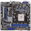
CPU Chipset Memory Expansion Slot Graphics Audio LAN - Micro ATX Form Factor: 8.9-in x 8.5-in, 22.6 cm x 21.6 cm - Solid Capacitor for CPU power - Support for Socket FM1 100W processors - Supports AMD's Cool 'n' QuietTM Technology - UMI-Link GEN2 - AMD A55 FCH (Hudson-D2) - Dual Channel DDR3 - ASRock A55M-HVS | User Manual - Page 7
connectors, support RAID (RAID 0, RAID 1 and RAID 10), NCQ, AHCI and "Hot Plug" functions - 1 x IR header - 1 x CIR header - 1 x Print port header - 1 x COM port header - CPU/Chassis/Power FAN connector - 24 pin ATX power connector - 8 pin 12V power connector - Front panel audio connector - 3 x USB - ASRock A55M-HVS | User Manual - Page 8
/Chassis Quiet Fan - CPU/Chassis Fan Multi-Speed Control - Voltage Monitoring: +12V, +5V, +3.3V, Vcore OS - Microsoft® Windows® 7 / 7 64-bit / VistaTM / VistaTM 64-bit / XP SP3 / XP 64-bit compliant Certifications - FCC, CE, WHQL - ErP/EuP Ready (ErP/EuP ready power supply is required) (see - ASRock A55M-HVS | User Manual - Page 9
2400/1866/1600MHz memory speed is supported depends on the CPU you adopt. If you want to adopt DDR3 2400/1866/1600 memory module on this motherboard, please refer to the memory support list on our website for the compatible memory modules. ASRock website http://www.asrock.com 3. Due to the operating - ASRock A55M-HVS | User Manual - Page 10
the completed system shall be under 1.00W in off mode condition. To meet EuP standard, an EuP ready motherboard and an EuP ready power supply are required. According to Intel's suggestion, the EuP ready power supply must meet the standard of 5v standby power ef ciency is higher than 50% under 100 mA - ASRock A55M-HVS | User Manual - Page 11
B: USB5 USB 2.0 T: USB0 B: USB1 Dual Graphics RoHS ErP/EuP Ready RJ-45 LAN Designed in Taipei LAN AUDIO CODEC PWR_FAN1 32Mb BIOS PCIE1 A55M-HVS PCIE2 AMD A55 FCH (Hudson-D2) Chipset PCI1 CMOS BATTERY Super I/O HD_AUDIO1 1 USB10_11 1 USB8_9 1 USB6_7 1 1 CIR1 IR1 1 CHA_FAN1 CLRCMOS1 - ASRock A55M-HVS | User Manual - Page 12
system. Please follow below instructions according to the OS you install. For Windows® XP / XP 64-bit OS: Please click "VIA HD Audio Deck" icon , and click "Speaker". Then you are allowed to select "2 Channel" or "4 Channel". Click "Power" to save your change. For Windows® 7 / 7 64-bit / VistaTM - ASRock A55M-HVS | User Manual - Page 13
or remove any component, ensure that the power is switched off or the power cord is detached from the power supply. Failure to do so may cause severe damage to the motherboard, peripherals, and/or components. 1. Unplug the power cord from the wall socket before touching any component. 2. To avoid - ASRock A55M-HVS | User Manual - Page 14
Up The Socket Lever CPU Golden Triangle Socket Corner Small Triangle STEP 2 / STEP 3: STEP 4: Match The CPU Golden Triangle Push Down And Lock To The Socket Corner Small The Socket Lever Triangle 2.2 Installation of CPU Fan and Heatsink After you install the CPU into this motherboard, it is - ASRock A55M-HVS | User Manual - Page 15
memory module into DDR3 slot;otherwise, this motherboard and DIMM may be damaged. 2. If you install only one memory module or two non-identical memory modules, it is unable to activate the Dual Channel Memory Technology. Installing a DIMM Please make sure to disconnect power supply before adding - ASRock A55M-HVS | User Manual - Page 16
, please make sure that the power supply is switched off or the power cord is unplugged. Please read the documentation of the expansion card and make necessary hardware settings for the card before you start the installation. Remove the system unit cover (if your motherboard is already installed in - ASRock A55M-HVS | User Manual - Page 17
HD 65XX/64XX graphics processor and a motherboard based on an AMD A55 FCH (Hudson-D2) integrated chipset, all operating in a Windows® 7 environment. Please refer to below PCI Express graphics card support list for AMD Dual Graphics. For the future update of more compatible PCI Express graphics cards - ASRock A55M-HVS | User Manual - Page 18
" on your Windows® taskbar to enter AMD VISION Engine Control Center. AMD VISION Engine Control Center Step 8. In AMD VISION Engine Control Center, please choose "Performance". Click "AMD CrossFireTM". Step 9. Click "Enable CrossFireTM" and click "Apply" to save your change. Step 10. Reboot your - ASRock A55M-HVS | User Manual - Page 19
motherboard. This motherboard also provides independent display controllers for D-Sub and HDMI to support dual VGA output so that D-sub and HDMI , or connect HDMI monitor cable to HDMI port on the I/O panel. D-Sub port HDMI port 2. If you have installed onboard VGA driver from our support CD to your - ASRock A55M-HVS | User Manual - Page 20
VGA card is inserted to this motherboard. 4. Install the onboard VGA driver and the add-on PCI Express VGA card driver to your system. If you have installed the drivers already, there is no need to install them again. 5. Set up a multi-monitor display. For Windows® XP / XP 64-bit OS: Right click the - ASRock A55M-HVS | User Manual - Page 21
Windows supported on this motherboard. To use HDCP function with this motherboard, you need to adopt the monitor that supports HDCP function as well. Therefore, you can enjoy the superior display quality with high-de nition HDCP encryption contents. Please refer to below instruction -top box and the - ASRock A55M-HVS | User Manual - Page 22
chassis on the market. 3. The Multi-Angle CIR Receiver does not support Hot-Plug function. Please install it before you boot the system. * ASRock Smart Remote is only supported by some of ASRock motherboards. Please refer to ASRock website for the motherboard support list: http://www.asrock.com 22 - ASRock A55M-HVS | User Manual - Page 23
default setup, please turn off the computer and unplug the power cord from the power supply. After waiting for 15 seconds, use a jumper cap to short pin2 and pin3 on CLRCMOS1 for 5 seconds. However, please do not clear the CMOS right after you update the BIOS. If you need to clear the CMOS when you - ASRock A55M-HVS | User Manual - Page 24
or the SATAII connector on this motherboard. This is an interface for print port cable that allows convenient connection of printer devices. Besides six default USB 2.0 ports on the I/O panel, there are three USB 2.0 headers on this motherboard. Each USB 2.0 header can support two USB 2.0 ports. - ASRock A55M-HVS | User Manual - Page 25
GND IRTX IRRX ATX+5VSB This header supports an optional audio devices. 1. High De nition Audio supports Jack Sensing, but the panel wire on the chassis must support HDA to function correctly. Please follow the instruction in our manual and chassis manual Power Switch): Connect to the power switch - ASRock A55M-HVS | User Manual - Page 26
function. If you plan to connect the 3-Pin CPU fan to the CPU fan connector on this motherboard, please connect it to Pin 1-3. Pin 1-3 Connected 3-Pin Fan Installation ATX Power Connector (24-pin ATXPWR1) (see p.11 No. 6) 12 24 Please connect an ATX power supply to this connector. 1 13 26 - ASRock A55M-HVS | User Manual - Page 27
this motherboard provides 24-pin ATX power connector, 12 24 it can still work if you adopt a traditional 20-pin ATX power supply. To use the 20-pin ATX power supply, please plug your power supply along with Pin 1 and Pin 13. 20-Pin ATX Power Supply Installation 1 13 ATX 12V Power Connector - ASRock A55M-HVS | User Manual - Page 28
. 2.11 Hot Plug and Hot Swap Functions for SATA / SATAII HDDs This motherboard supports Hot Plug and Hot Swap functions for SATA / SATAII in RAID / AHCI mode. AMD A55 FCH (Hudson-D2) chipset provides hardware support for Advanced Host controller Interface (AHCI), a new programming interface for SATA - ASRock A55M-HVS | User Manual - Page 29
supports Hot Plug feature for SATA / SATAII HDD in RAID / AHCI mode. Please read below operation guide of Hot Plug feature carefully. Before you process the SATA / SATAII HDD Hot Plug, please check below cable accessories from the motherboard gift box pack. A. 7-pin SATA data cable B. SATA power - ASRock A55M-HVS | User Manual - Page 30
instruction sequence to process the Hot Plug, improper procedure will cause the SATA / SATAII HDD damage and data loss. Step 1 Please connect SATA power cable 1x4-pin end Step 2 Connect SATA data cable to (White) to the power supply 1x4-pin cable. the motherboard's SATAII connector. SATA power - ASRock A55M-HVS | User Manual - Page 31
-detected and listed on the support CD driver page. Please follow the order from up to bottom side to install those required drivers. Therefore, the drivers you install can work properly. 2.14 Installing Windows® 7 / 7 64-bit / VistaTM / VistaTM 64-bit / XP / XP 64-bit With RAID Functions If you - ASRock A55M-HVS | User Manual - Page 32
path in the Support CD: .. \ RAID Installation Guide STEP 4: Install Windows® XP / XP 64-bit OS on your system. After step 1, 2, 3, you can start to install Windows® XP / XP 64-bit OS on your system. At the beginning of Windows® setup, press F6 to install a third-party RAID driver. When prompted - ASRock A55M-HVS | User Manual - Page 33
the OS you install. 2.15.1 Installing Windows® XP / XP 64-bit Without RAID Functions If you want to install Windows® XP / XP 64-bit on your SATA / SATAII HDDs without RAID functions, please follow below steps. Using SATA / SATAII HDDs with NCQ and Hot Plug functions (AHCI mode) STEP 1: Set up UEFI - ASRock A55M-HVS | User Manual - Page 34
VistaTM / VistaTM 64-bit Without RAID Functions If you want to install Windows® 7 / 7 64-bit / VistaTM / VistaTM 64-bit on your SATA / SATAII HDDs without RAID functions, please follow below steps. Using SATA / SATAII HDDs with NCQ and Hot Plug functions (AHCI mode) STEP 1: Set up UEFI. A. Enter - ASRock A55M-HVS | User Manual - Page 35
motherboard stores the UEFI SETUP UTILITY. You may run the UEFI SETUP UTILITY when you start up the computer. Please press or during the Power-On-Self-Test (POST) to enter the UEFI SETUP UTILITY, otherwise, POST OC Tweaker To set up overclocking features Advanced To set up the - ASRock A55M-HVS | User Manual - Page 36
3.1.2 Navigation Keys Please check the following table for the function description of each navigation key. Navigation Key(s) / / + / Function Description Moves cursor left or right to select Screens Moves cursor up or down to select items To change option for the - ASRock A55M-HVS | User Manual - Page 37
overclocking features. CPU Configuration Spread Spectrum This item should always be [Auto] for better system stability. AMD Turbo Core Technology This item appears only when the processor you adopt supports Auto] by default. If it is set to [Manual], you may adjust the value of Processor Frequency and - ASRock A55M-HVS | User Manual - Page 38
Enable Use this item to enable or disable DDR power down mode. Bank Interleaving Interleaving allows memory accesses to be is [Auto]. CAS# Latency (tCL) Use this item to change CAS# Latency (tCL) Auto/Manual setting. The default is [Auto]. RAS# to CAS# Delay (tRCD) Use this item to change RAS# to - ASRock A55M-HVS | User Manual - Page 39
Four Activate Window (tFAW) Auto/Manual setting. The default is [Auto]. Voltage Control DRAM Voltage Use this to select DRAM Voltage. The default value is [Auto]. APU PCIE Voltage VDDP Use this to select APU PCIE Voltage VDDP. The default value is [Auto]. CPU Load-Line Calibration CPU Load-Line - ASRock A55M-HVS | User Manual - Page 40
you may set the con gurations for the following items: CPU Con guration, Nouth Bridge Con guration, South Bridge Con guration in Flash ROM. This convenient UEFI update tool allows you to update system UEFI without entering operating systems rst like MS-DOS or Windows®. Just launch this tool and save - ASRock A55M-HVS | User Manual - Page 41
]. If you install Windows® 7 / VistaTM and want to enable this function, please set this item to [Enabled]. Please note that enabling this function may reduce CPU voltage and memory frequency, and lead to system stability or compatibility issue with some memory modules or power supplies. Please set - ASRock A55M-HVS | User Manual - Page 42
], [32MB], [64MB], [128MB], [256MB] and [512MB]. Onboard HDMI HD Audio This allows you to enable or disable the "Onboard HDMI HD Audio" feature. Dual Graphics This item appears only when you install AMD RADEON HD6670 / 6570 / 6450 graphics card on this motherboard. Use this to enable or disable Dual - ASRock A55M-HVS | User Manual - Page 43
. Front Panel Select [Auto] or [Disabled] for the onboard HD Audio Front Panel. Onboard LAN This allows you to enable or disable the onboard LAN feature. Good Night LED Enable this option to turn off Power LED and Port80 LED when the system is power on. The keyboard LED will also be turned off in - ASRock A55M-HVS | User Manual - Page 44
. The default value of this option is [IDE Mode]. Con guration options: [AHCI Mode], [RAID Mode] and [IDE Mode]. If you set this item to RAID mode, it is suggested to install SATA ODD driver on SATA_5 and SATA_6 ports. SATA IDE Combined Mode This item is for SATA_5 and SATA_6 ports. Use this item - ASRock A55M-HVS | User Manual - Page 45
onboard infrared port. Con guration options: [2F8 / IRQ3] and [2E8 / IRQ3]. Parallel Port Use this item to enable or disable the onboard parallel port. Device Mode Use this item to change the Printer Port mode. Change Settings Use this item to select an optional setting for Super IO device. 45 - ASRock A55M-HVS | User Manual - Page 46
enable or disable PS/2 keyboard to turn on the system from the power-soft-off mode. PCI Devices Power On Use this item to enable or disable PCI devices to turn on the system from the power-soft-off mode. Ring-In Power On Use this item to enable or disable Ring-In signals to turn - ASRock A55M-HVS | User Manual - Page 47
ACPI HPET table Use this item to enable or disable ACPI HPET Table. The default value is [Enabled]. Please set this option to [Enabled] if you plan to use this motherboard to submit Windows® VistaTM certi cation. 47 - ASRock A55M-HVS | User Manual - Page 48
to below descriptions for the details of these four options: [Enabled] - Enables support for legacy USB. [Auto] - Enables legacy support if USB devices are connected. [Disabled] - USB devices are not allowed to Only] - USB devices are allowed to use only under UEFI setup and Windows / Linux OS. 48 - ASRock A55M-HVS | User Manual - Page 49
on your system, including the parameters of the CPU temperature, motherboard temperature, CPU fan speed, chassis fan speed, and the critical voltage. CPU Fan 1 Setting This allows you to set the CPU fan 1 speed. Con guration options: [Full On] and [Automatic Mode]. The default is value [Full On - ASRock A55M-HVS | User Manual - Page 50
or disable the feature of Boot Failure Guard. Boot Failure Guard Count Enable or disable the feature of Boot Failure Guard Count. Boot From Onboard LAN Use this item to enable or disable the Boot From Onboard - ASRock A55M-HVS | User Manual - Page 51
3.7 Security Screen In this section, you may set or change the supervisor/user password for the system. For the user password, you may also clear it. 51 - ASRock A55M-HVS | User Manual - Page 52
3.8 Exit Screen Save Changes and Exit When you select this option, it will pop-out the following message, "Save con guration changes and exit setup?" Select [OK] to save the changes and exit the UEFI SETUP UTILITY. Discard Changes and Exit When you select this option, it will pop-out the following - ASRock A55M-HVS | User Manual - Page 53
4.1 Install Operating System This motherboard supports various Microsoft® Windows® operating systems: 7 / 7 64-bit / VistaTM / VistaTM 64-bit / XP SP3 / XP 64-bit. Because motherboard settings and hardware options vary, use the setup procedures in this chapter for general reference only. Refer - ASRock A55M-HVS | User Manual - Page 54
Installing OS on a HDD Larger Than 2TB in AHCI Mode This motherboard is adopting UEFI BIOS that allows Windows® OS to be installed on a large size HDD (>2TB). Please follow below procedure to install the operating system. 1. Please make sure to use Windows® VistaTM 64-bit (with SP1 or above) or - ASRock A55M-HVS | User Manual - Page 55
or Windows® 7 64-bit. 2. Press or at system POST. Set RAID Mode in UEFI Setup Utility > Advanced > Storage Con guration > SATA Mode. 3. Choose onboard RAID 3TB+ unlocker > UEFI Mode For GPT partition. Press to save the change and exit. 4. Press to enter Boot Manual. Choose - ASRock A55M-HVS | User Manual - Page 56
7. And then key in drvcfg -s [Drv number] [Ctrl number] to enter Raid Utility. For example: key in drvcfg -s 4E B5. 8. Choose Logical Drive Main Menu to set up Raid Drive. 9. Choose Logical Drive Create Menu to create a Raid Drive. 10. Choose Usable Physical Drive List to select Raid HDD. 56 - ASRock A55M-HVS | User Manual - Page 57
Ld Size setting, and key in the Raid size. 13. After set up Raid size, please click Start to Create. 14. Press to exit Utility. 15. During reboot, please press to enter Boot Manual. Choose UEFI: SCSI CD/DVD Drive. * This option only shows on Windows® 7 64-bit and VistaTM 64-bit - ASRock A55M-HVS | User Manual - Page 58
Guide to install OS. If you install Windows® 7 64-bit / VistaTM 64-bit in a large hard disk (ex. Disk volume > 2TB), it may take more time to boot into Windows® or install driver/ utilities. If you encounter this problem, you will need to following instructions to x this problem. Windows - ASRock A55M-HVS | User Manual - Page 59
B. Disable "Volume Shadow Copy" service. a. Type "computer management" in the Start Menu, then press "Enter". b. Go to "Services and Applications>Services"; Then double click "Volume Shadow Copy". c. Set "Startup type" to "Disable" then Click "OK". 59 - ASRock A55M-HVS | User Manual - Page 60
C. Reboot your system. D. After reboot, please start to install motherboard drivers and utilities. Windows® 7 64-bit: A. Please request the hot x KB2505454 thru this link: http://support.microsoft.com/kb/2505454/ B. After installing Windows® 7 64-bit, install the hot x kb2505454. (This may take long
-
 1
1 -
 2
2 -
 3
3 -
 4
4 -
 5
5 -
 6
6 -
 7
7 -
8
-
9
-
10
-
11
-
12
-
13
-
14
-
15
-
16
-
17
-
18
-
19
-
20
-
21
-
22
-
23
-
24
-
25
-
26
-
27
-
28
-
29
-
30
-
31
-
32
-
33
-
34
-
35
-
36
-
37
-
38
-
39
-
40
-
41
-
42
-
43
-
44
-
45
-
46
-
47
-
48
-
49
-
50
-
51
-
52
-
53
-
54
-
55
-
56
-
57
-
58
-
59
-
60
 |
 |

1
A55M-HVS
User Manual
Version 1.0
Published August 2011
Copyright©2011 ASRock INC. All rights reserved.