ASRock A75 Extreme6 User Manual
ASRock A75 Extreme6 Manual
 |
View all ASRock A75 Extreme6 manuals
Add to My Manuals
Save this manual to your list of manuals |
ASRock A75 Extreme6 manual content summary:
- ASRock A75 Extreme6 | User Manual - Page 1
A75 Extreme6 User Manual Version 1.1 Published June 2011 Copyright©2011 ASRock INC. All rights reserved. 1 - ASRock A75 Extreme6 | User Manual - Page 2
purchaser for backup purpose, without written consent of ASRock Inc. Products and corporate names appearing in this manual may or may not be registered trademarks or copyrights , USA ONLY The Lithium battery adopted on this motherboard contains Perchlorate, a toxic substance controlled in Perchlorate - ASRock A75 Extreme6 | User Manual - Page 3
and Quad CrossFireXTM Operation Guide 20 2.6 Dual Graphics Operation Guide 26 2.7 Dual Monitor and Surround Display Features 28 2.8 ASRock Smart Remote Installation Guide 31 2.9 Jumpers Setup 32 2.10 Onboard Headers and Connectors 33 2.11 Smart Switches 39 2.12 Dr. Debug 40 2.13 Serial ATA3 - ASRock A75 Extreme6 | User Manual - Page 4
UEFI Menu Bar 51 3.1.2 Navigation Keys 52 3.2 Main Screen 52 3.3 OC Tweaker Screen 53 3.4 Advanced Screen 56 3.4.1 CPU Con guration 57 3.4.2 68 4. Software Support 69 4.1 Install Operating System 69 4.2 Support CD Information 69 4.2.1 Running Support CD 69 4.2.2 Drivers Menu 69 4.2.3 - ASRock A75 Extreme6 | User Manual - Page 5
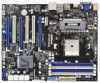
Motherboard (ATX Form Factor: 12.0-in x 9.6-in, 30.5 cm x 24.4 cm) ASRock A75 Extreme6 Quick Installation Guide ASRock A75 Extreme6 Support CD 4 x Serial ATA (SATA) Data Cables (Optional) 1 x 3.5mm Audio Cable (Optional) 1 x I/O Panel Shield ASRock Reminds You... To get better performance in Windows - ASRock A75 Extreme6 | User Manual - Page 6
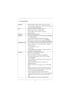
Polymer Capacitors) - Support for Socket FM1 100W processors - Advanced V8 + 2 Power Phase Design - Supports AMD's Cool 'n' QuietTM Technology - UMI-Link GEN2 - AMD A75 FCH (Hudson-D3) - Dual Channel DDR3 Memory Technology (see CAUTION 1) - 4 x DDR3 DIMM slots - Support DDR3 2400+(OC)/1866/1600/1333 - ASRock A75 Extreme6 | User Manual - Page 7
Switch with LED - HD Audio Jack: Rear Speaker/Central/Bass/Line in/Front Speaker/Microphone (see CAUTION 7) - 6 x SATA3 6.0 Gb/s connectors by AMD A75 FCH (Hudson-D3), support RAID (RAID 0, RAID 1 and RAID 10), NCQ, AHCI and "Hot Plug" functions - 2 x SATA3 6.0 Gb/s connectors by ASMedia ASM1061 - ASRock A75 Extreme6 | User Manual - Page 8
jumperfree - SMBIOS 2.3.1 Support - DRAM, VDDP, VDDR, SB Voltage Multi-adjustment - Drivers, Utilities, AntiVirus Software (Trial Version), AMD Live! Explorer, AMD Fusion, CyberLink MediaEspresso 6.5 Trial, ASRock Software Suite (CyberLink DVD Suite - OEM and Trial) - ASRock Extreme Tuning Utility - ASRock A75 Extreme6 | User Manual - Page 9
by overclocking. CAUTION! 1. This motherboard supports Dual Channel Memory Technology. Before you implement Dual Channel Memory Technology, make sure to read the installation guide of memory modules on page 17 for proper installation. 2. Whether 2400/1866/1600MHz memory speed is supported depends - ASRock A75 Extreme6 | User Manual - Page 10
procedures of ASRock Extreme Tuning Utility (AXTU). ASRock website: http://www.asrock.com 9. ASRock Instant Flash is a BIOS ash utility embedded in Flash ROM. This convenient BIOS update tool allows you to update system BIOS without entering operating systems rst like MS-DOS or Windows®. With this - ASRock A75 Extreme6 | User Manual - Page 11
ASRock On/Off Play Technology allows users to enjoy the great audio experience from the portable audio devices, such like MP3 player or mobile phone to your PC, even when the PC is turned off (or in ACPI S5 mode)! This motherboard the CPU and the heatsink when you install the PC system. 15. EuP, stands - ASRock A75 Extreme6 | User Manual - Page 12
Extreme6 Dual Graphics PCIE2 LAN PCI1 SATA3 6Gb/s CMOS BATTERY PCI2 PCIE3 32Mb BIOS RoHS PCI3 AUDIO CODEC 1394a 1 CLRCMOS1 HD_AUDIO1 FRONT_1394 1 1 HDMI_SPDIF1 1 PCIE4 USB6_7 1 1 CIR1 USB10_11 1 SATA3_A1 XFast USB AMD A75 FCH (Hudson-D3) Chipset SATA3_4 SATA3_2 IR1 1 Super - ASRock A75 Extreme6 | User Manual - Page 13
Speaker (Black) Optical SPDIF Out Port Line In (Light Blue) Front Speaker (Lime) 10 11 12 **** 13 14 15 16 17 Microphone (Pink) USB 3.0 Ports (USB01) HDMI Port DVI-D Port USB 3.0 Ports (USB45) * It is recommended to install the USB Keyboard/Mouse cable to USB 2.0 ports (USB23) instead of USB 3.0 - ASRock A75 Extreme6 | User Manual - Page 14
Primary output" to use Rear Speaker, Central/Bass, and Front Speaker, or select "Realtek HDA Audio 2nd output" to use front panel audio. **** eSATA3 connector supports SATA Gen3 in cable 1M. 14 - ASRock A75 Extreme6 | User Manual - Page 15
is an ATX form factor (12.0-in x 9.6-in, 30.5 cm x 24.4 cm) motherboard. Before you install the motherboard, study the con guration of your chassis to ensure that the motherboard ts into it. Pre-installation Precautions Take note of the following precautions before you install motherboard components - ASRock A75 Extreme6 | User Manual - Page 16
The Socket Corner Small The Socket Lever Triangle 2.2 Installation of CPU Fan and Heatsink After you install the CPU into this motherboard, it is necessary to install a Page 12, No. 6). For proper installation, please kindly refer to the instruction manuals of the CPU fan and the heatsink. 16 - ASRock A75 Extreme6 | User Manual - Page 17
2.3 Installation of Memory Modules (DIMM) This motherboard provides four 240-pin DDR3 (Double Data Rate 3) DIMM slots, and supports Dual Channel Memory Technology. For dual channel con- guration, you always need to install identical (the same brand, speed, size and chip-type) DDR3 DIMM pair in the - ASRock A75 Extreme6 | User Manual - Page 18
Installing a DIMM Please make sure to disconnect power supply before adding or removing break notch break The DIMM only ts in one correct orientation. It will cause permanent damage to the motherboard and the DIMM if you force the DIMM into the slot at incorrect orientation. Step 3. Firmly insert - ASRock A75 Extreme6 | User Manual - Page 19
Blue) is used for PCI Express x16 lane width graphics cards, or used to install PCI Express graphics cards to support CrossFireXTM function. PCIE4 (PCIE x16 slot; Blue) card before you start the installation. Remove the system unit cover (if your motherboard is already installed in a chassis). Remove - ASRock A75 Extreme6 | User Manual - Page 20
. Currently CrossFireXTM feature is supported with Windows® XP with Service Pack 2 / VistaTM / 7 OS. 3-way CrossFireXTM and Quad CrossFireXTM feature are supported with Windows® VistaTM / 7 OS only. Please check AMD website for AMD CrossFireXTM driver updates. 1. If a customer incorrectly configures - ASRock A75 Extreme6 | User Manual - Page 21
Step 2. Connect two Radeon graphics cards by installing CrossFire Bridge on CrossFire Bridge Interconnects on the top of Radeon graphics cards. (CrossFire Bridge is provided with the graphics card you purchase, not bundled with this motherboard. Please refer to your graphics card vendor for details - ASRock A75 Extreme6 | User Manual - Page 22
to section "Expansion Slots". Step 2. Install one Radeon graphics card to PCIE3 slot. For the proper installation procedures, please refer to section "Expansion Slots". Step 3. Install one Radeon graphics card to PCIE4 slot. For the proper installation procedures, please refer to section "Expansion - ASRock A75 Extreme6 | User Manual - Page 23
CrossFireTM Bridge Step 5. Connect the DVI monitor cable to the DVI connector on the Radeon graphics card on PCIE2 slot. (You may use the DVI to D-Sub adapter to convert the DVI connector to D-Sub interface, and then connect the D-Sub monitor cable to the DVI to D-Sub adapter.) 23 - ASRock A75 Extreme6 | User Manual - Page 24
installed Catalyst drivers prior to installation. Please check AMD website for AMD driver updates. Step 3. Step 4. Step 5. Install the required drivers to your system. For Windows® XP OS: A. AMD recommends Windows® XP Service Pack 2 or higher to be installed (If you have Windows® XP Service - ASRock A75 Extreme6 | User Manual - Page 25
You can freely enjoy the bene t of CrossFireXTM, 3-Way CrossFireXTM or Quad CrossFireXTM feature. * CrossFireXTM appearing here is a registered trademark of AMD Technologies Inc., and is used only for identi cation or explanation and to the owners' bene t, without intent to infringe. * For further - ASRock A75 Extreme6 | User Manual - Page 26
Dual Graphics system includes an AMD Radeon HD 65XX/64XX graphics processor and a motherboard based on an AMD A75 FCH (Hudson-D3) integrated chipset, all operating in a Windows® 7 environment. Please refer to below PCI Express graphics card support list for AMD Dual Graphics. For the future update - ASRock A75 Extreme6 | User Manual - Page 27
9. Click "Enable CrossFireTM" and click "Apply" to save your change. Step 10. Reboot your system. Then you can freely enjoy the bene t of Dual Graphics feature. * Dual Graphics appearing here is a registered trademark of AMD Technologies Inc., and is used only for identi cation or explanation and to - ASRock A75 Extreme6 | User Manual - Page 28
-D, D-Sub and HDMI), you can easily enjoy the bene ts of dual monitor feature without installing any add-on VGA card to this motherboard. This motherboard also provides independent display controllers for DVI-D, D-Sub and HDMI to support dual VGA output so that DVI-D, D-sub and HDMI can drive same - ASRock A75 Extreme6 | User Manual - Page 29
Enter "Share Memory" option to adjust the memory capability to [ motherboard. 4. Install the onboard VGA driver and the add-on PCI Express VGA card driver to your system. If you have installed the drivers already, there is no need to install them again. 5. Set up a multi-monitor display. For Windows - ASRock A75 Extreme6 | User Manual - Page 30
For Windows® 7 / 7 64-bit supported on this motherboard. To use HDCP function with this motherboard, you need to adopt the monitor that supports HDCP function as well. Therefore, you can enjoy the superior display quality with high-de nition HDCP encryption contents. Please refer to below instruction - ASRock A75 Extreme6 | User Manual - Page 31
chassis on the market. 3. The Multi-Angle CIR Receiver does not support Hot-Plug function. Please install it before you boot the system. * ASRock Smart Remote is only supported by some of ASRock motherboards. Please refer to ASRock website for the motherboard support list: http://www.asrock.com 31 - ASRock A75 Extreme6 | User Manual - Page 32
need to clear the CMOS when you just nish updating the BIOS, you must boot up the system rst, and then shut it down before you do the clear-CMOS action. Please be noted that the password, date, time, user default pro le, 1394 GUID and MAC address will be cleared only if - ASRock A75 Extreme6 | User Manual - Page 33
10 Onboard Headers and Connectors Onboard headers and connectors are NOT jumpers. Do NOT place jumper caps over these headers and connectors. Placing jumper caps over the headers and connectors will cause permanent damage of the motherboard ATA3 (SATA3) connectors support SATA data cables for - ASRock A75 Extreme6 | User Manual - Page 34
p.12 No. 10) USB_PWR P-9 P+9 GND DUMMY 1 GND P+8 P-8 USB_PWR USB_PWR P-11 P+11 GND DUMMY 1 GND P+10 P-10 USB_PWR IntA_P2_D+ GND IRTX IRRX ATX+5VSB Besides two default USB 2.0 ports on the I/O panel, there are three USB 2.0 headers on this motherboard. Each USB 2.0 header can support two USB 2.0 - ASRock A75 Extreme6 | User Manual - Page 35
support HDA to function correctly. Please follow the instruction in our manual and chassis manual to install your system. 2. If you use AC'97 audio panel, please install the front mic. For Windows® XP / XP 64-bit OS: Select "Mixer". Select "Recorder". Then click "FrontMic". For Windows® 7 / 7 64-bit - ASRock A75 Extreme6 | User Manual - Page 36
provides 4-Pin CPU fan (Quiet Fan) support, the 3-Pin CPU fan still can work successfully even without the fan speed control function. If you plan to connect the 3-Pin CPU fan to the CPU fan connector on this motherboard, please connect it to Pin 1-3. Pin 1-3 Connected 3-Pin Fan Installation 36 - ASRock A75 Extreme6 | User Manual - Page 37
supply along with Pin 1 and Pin 13. 20-Pin ATX Power Supply Installation 1 13 ATX 12V Power Connector (8-pin ATX12V1) (see p.12 No. 1) 4 8 1 5 Please connect an ATX 12V power supply to this connector. Though this motherboard provides 8-pin ATX 12V power connector, it can still work if you - ASRock A75 Extreme6 | User Manual - Page 38
HDMI_SPDIF Header (2-pin HDMI_SPDIF1) (see p.12 No. 33) 1 GND SPDIFOUT HDMI_SPDIF header, providing SPDIF audio output to HDMI VGA card, allows the system to connect HDMI Digital TV/ projector/LCD devices. Please connect the HDMI_SPDIF connector of HDMI VGA card to this header. 38 - ASRock A75 Extreme6 | User Manual - Page 39
2.11 Smart Switches This motherboard has three smart switches: power switch, reset switch and clear CMOS switch, allowing users to quickly turn on/off or reset the system or clear - ASRock A75 Extreme6 | User Manual - Page 40
) data reading Memory initialization. Memory presence detection Memory initialization. Programming memory timing information Memory initialization. Con guring memory Memory initialization (other) Reserved for ASL (see ASL Status Codes section below) Memory Installed CPU post-memory initialization is - ASRock A75 Extreme6 | User Manual - Page 41
memory size or memory modules do not match Memory initialization error. No usable memory detected Unspeci ed memory initialization error Memory not installed Invalid CPU type or Speed CPU mismatch CPU self test failed or possible CPU cache error CPU micro-code is not found or micro-code update - ASRock A75 Extreme6 | User Manual - Page 42
0x9C 0x9D 0x9E - 0x9F 0xA0 0xA1 0xA2 0xA3 0xA4 0xA5 Installation of the South Bridge Runtime Services CPU DXE initialization is started CPU DXE initialization (CPU module codes Boot Device Selection (BDS) phase is started Driver connecting is started PCI Bus initialization is started PCI Bus - ASRock A75 Extreme6 | User Manual - Page 43
(see ASL Status Codes section below) Ready To Boot event Legacy Boot event Exit Boot Services event Runtime Set Virtual Address MAP Begin Runtime Set Virtual Address MAP End Legacy Option ROM Boot Option is failed (StartImage returned error) Flash update is failed Reset protocol is not available 43 - ASRock A75 Extreme6 | User Manual - Page 44
ATA3 (SATA3) Hard Disks Installation This motherboard adopts AMD A75 FCH (Hudson-D3) chipset that supports Serial ATA3 (SATA3) hard disks and RAID (RAID 0, RAID 1 and RAID 10) functions for SATA3_0 to SATA3_5 connectors. It also adopts ASMedia ASM1061 chipset that supports Serial ATA3 (SATA3) hard - ASRock A75 Extreme6 | User Manual - Page 45
Please make sure the SATA3 driver is installed into system properly. The latest SATA3 driver is available on our support website: www.asrock.com 4. Make sure to use the SATA power cable & data cable, which are from our motherboard package. 5. Please follow below instructions step by step to reduce - ASRock A75 Extreme6 | User Manual - Page 46
data cable to end (White) to the power supply 1x4-pin the motherboard's SATAII / SATA3 cable. connector. SATA power cable 1x4-pin power of attention, before you process the Hot Unplug: Please do follow below instruction sequence to process the Hot Unplug, improper procedure will cause the SATA3 - ASRock A75 Extreme6 | User Manual - Page 47
and listed on the support CD driver page. Please follow the order from up to bottom side to install those required drivers. Therefore, the drivers you install can work properly. 2.17 Installing Windows® 7 / 7 64-bit / VistaTM / VistaTM 64-bit / XP / XP 64-bit With RAID Functions If you want - ASRock A75 Extreme6 | User Manual - Page 48
refer to the BIOS RAID installation guide part of the document in the following path in the Support CD: .. \ RAID Installation Guide STEP 3: Make a SATA3 Driver Diskette. Make a SATA3 driver diskette by following section 2.17.1 step 2 on page 47. STEP 4: Install Windows® 7 / 7 64-bit / VistaTM - ASRock A75 Extreme6 | User Manual - Page 49
OS on your system. At the beginning of Windows® setup, press F6 to install a third-party AHCI driver. When prompt- ed, insert the SATA3 driver diskette containing the AMD AHCI driver. After reading the oppy disk, the driver will be presented. Select the driver to install according to the OS you - ASRock A75 Extreme6 | User Manual - Page 50
® 7 / 7 64-bit / VistaTM / VistaTM 64-bit Without RAID Functions If you want to install Windows® 7 / 7 64-bit / VistaTM / VistaTM 64-bit on your SATA3 HDDs without RAID functions, please follow below steps. Using SATA3 HDDs with NCQ and Hot Plug functions (AHCI mode) STEP 1: Set up UEFI. A. Enter - ASRock A75 Extreme6 | User Manual - Page 51
to con gure your system. The SPI Memory on the motherboard stores the UEFI SETUP UTILITY. You may Because the UEFI software is constantly being updated, the following UEFI setup screens and descriptions the system time/date information OC Tweaker To set up overclocking features Advanced To set up - ASRock A75 Extreme6 | User Manual - Page 52
3.1.2 Navigation Keys Please check the following table for the function description of each navigation key. Navigation Key(s) / / + / Function Description Moves cursor left or right to select Screens Moves cursor up or down to select items To change option for the - ASRock A75 Extreme6 | User Manual - Page 53
Screen In the OC Tweaker screen, you can set up overclocking features. CPU Configuration Overclock Mode Use this to select Overclock Mode. Configuration options: [Auto] and [Manual]. The default value is [Auto]. APU/PCIE Frequency (MHz) This item appears only when you set the item "Overclock Mode" to - ASRock A75 Extreme6 | User Manual - Page 54
If [Auto] is selected, the motherboard will detect the memory module(s) inserted and assigns appropriate frequency automatically Delay (tRCD) Auto/Manual setting. The default is [Auto]. Row Precharge Time (tRP) Use this item to change Row Precharge Time (tRP) Auto/Manual setting. The default - ASRock A75 Extreme6 | User Manual - Page 55
]. Read to Precharge (tRTP) Use this item to change Read to Precharge (tRTP) Auto/Manual setting. The default is [Auto]. Four Activate Window (tFAW) Use this item to change Four Activate Window (tFAW) Auto/Manual setting. The default is [Auto]. Voltage Control DRAM Voltage Use this to select DRAM - ASRock A75 Extreme6 | User Manual - Page 56
to malfunction. Instant Flash Instant Flash is a UEFI ash utility embedded in Flash ROM. This convenient UEFI update tool allows you to update system UEFI without entering operating systems rst like MS-DOS or Windows®. Just launch this tool and save the new UEFI le to your USB ash drive, oppy disk - ASRock A75 Extreme6 | User Manual - Page 57
The default value is [Disabled]. Cool 'n' Quiet Use this item to enable or disable AMD's Cool 'n' QuietTM technology. The default value is [Enabled]. Con guration options: [Enabled] and [Disabled]. If you install Windows® 7 / VistaTM and want to enable this function, please set this item to [Enabled - ASRock A75 Extreme6 | User Manual - Page 58
you to enable or disable the "Onboard HDMI HD Audio" feature. Dual Graphics This item appears only when you install AMD RADEON HD6670 / 6570 / 6450 graphics card on this motherboard. Use this to enable or disable Dual Graphics feature. If you enable this option, the primary monitor will be onboard - ASRock A75 Extreme6 | User Manual - Page 59
the system is power on. The keyboard LED will also be turned off in S1, S3 and S4 state. The default value is [Auto]. Onboard Debug Port LED Use this to enable or disable onboard debug port LED. The default value is [Auto]. 59 - ASRock A75 Extreme6 | User Manual - Page 60
SATA Mode. The default value of this option is [IDE Mode]. Con guration options: [AHCI Mode], [RAID Mode] and [IDE Mode]. If you set this item to RAID mode, it is suggested to install SATA ODD driver on SATA3_4 and SATA3_5 ports. SATA IDE Combined Mode This item is for SATA3_4 and SATA3_5 ports - ASRock A75 Extreme6 | User Manual - Page 61
3.4.5 Super IO Configuration Serial Port Use this item to enable or disable the onboard serial port. Serial Port Address Use this item to set the address for the onboard serial port. Con guration options: [3F8 / IRQ4] and [3E8 / IRQ4]. Infrared Port Use this item to enable or disable the onboard - ASRock A75 Extreme6 | User Manual - Page 62
3.4.6 ACPI Configuration Suspend to RAM Use this item to select whether to auto-detect or disable the Suspend-toRAM feature. Select [Auto] will enable this feature if the OS supports it. Check Ready Bit Use this item to enable or disable the feature Check Ready Bit. Restore on AC/Power Loss This - ASRock A75 Extreme6 | User Manual - Page 63
ACPI HPET table Use this item to enable or disable ACPI HPET Table. The default value is [Enabled]. Please set this option to [Enabled] if you plan to use this motherboard to submit Windows® VistaTM certi cation. 63 - ASRock A75 Extreme6 | User Manual - Page 64
compatibility issue, it is recommended to select [Disabled] to enter OS. [UEFI Setup Only] - USB devices are allowed to use only under UEFI setup and Windows / Linux OS. Legacy USB 3.0 Support Use this option to enable or disable legacy support for USB 3.0 devices. The default value is [Enabled]. 64 - ASRock A75 Extreme6 | User Manual - Page 65
hardware on your system, including the parameters of the CPU temperature, motherboard temperature, CPU fan speed, chassis fan speed, and the critical voltage the chassis fan 2 speed. Con guration options: [Full On] and [Manual Mode]. The default is value [Full On]. Chassis Fan 3 Setting This allows - ASRock A75 Extreme6 | User Manual - Page 66
3.6 Boot Screen In this section, it will display the available devices on your system for you to con gure the boot settings and the boot priority. Setup Prompt Timeout This shows the number of seconds to wait for setup activation key. 65535(0xFFFF) means inde nite waiting. Bootup Num-Lock If this - ASRock A75 Extreme6 | User Manual - Page 67
3.7 Security Screen In this section, you may set or change the supervisor/user password for the system. For the user password, you may also clear it. 67 - ASRock A75 Extreme6 | User Manual - Page 68
3.8 Exit Screen Save Changes and Exit When you select this option, it will pop-out the following message, "Save con guration changes and exit setup?" Select [OK] to save the changes and exit the UEFI SETUP UTILITY. Discard Changes and Exit When you select this option, it will pop-out the following - ASRock A75 Extreme6 | User Manual - Page 69
. Please install the necessary drivers to activate the devices. 4.2.3 Utilities Menu The Utilities Menu shows the applications software that the motherboard supports. Click on a speci c item then follow the installation wizard to install it. 4.2.4 Contact Information If you need to contact ASRock or - ASRock A75 Extreme6 | User Manual - Page 70
HDD Larger Than 2TB This motherboard is adopting UEFI BIOS that allows Windows® OS to be installed on a large size HDD (>2TB). Please follow below procedure to install the operating system. 1. Please make sure to use Windows® VistaTM 64-bit (with SP1 or above) or Windows® 7 64-bit. 2. Press or
-
 1
1 -
 2
2 -
 3
3 -
 4
4 -
 5
5 -
 6
6 -
 7
7 -
8
-
9
-
10
-
11
-
12
-
13
-
14
-
15
-
16
-
17
-
18
-
19
-
20
-
21
-
22
-
23
-
24
-
25
-
26
-
27
-
28
-
29
-
30
-
31
-
32
-
33
-
34
-
35
-
36
-
37
-
38
-
39
-
40
-
41
-
42
-
43
-
44
-
45
-
46
-
47
-
48
-
49
-
50
-
51
-
52
-
53
-
54
-
55
-
56
-
57
-
58
-
59
-
60
-
61
-
62
-
63
-
64
-
65
-
66
-
67
-
68
-
69
-
70
 |
 |

1
A75 Extreme6
User Manual
Version 1.1
Published June 2011
Copyright©2011 ASRock INC. All rights reserved.