ASRock A75 Extreme6 Quick Installation Guide
ASRock A75 Extreme6 Manual
 |
View all ASRock A75 Extreme6 manuals
Add to My Manuals
Save this manual to your list of manuals |
ASRock A75 Extreme6 manual content summary:
- ASRock A75 Extreme6 | Quick Installation Guide - Page 1
, please follow the related regulations in advance. "Perchlorate Material-special handling may apply, see www.dtsc.ca.gov/hazardouswaste/perchlorate" ASRock Website: http://www.asrock.com Published June 2011 Copyright©2011 ASRock INC. All rights reserved. 1 ASRock A75 Extreme6 Motherboard English - ASRock A75 Extreme6 | Quick Installation Guide - Page 2
Extreme6 Dual Graphics PCIE2 LAN PCI1 SATA3 6Gb/s CMOS BATTERY PCI2 PCIE3 32Mb BIOS RoHS PCI3 AUDIO CODEC 1394a 1 CLRCMOS1 HD_AUDIO1 FRONT_1394 1 1 HDMI_SPDIF1 1 PCIE4 USB6_7 1 1 CIR1 USB10_11 1 SATA3_A1 XFast USB AMD A75 FCH (Hudson-D3) Chipset SATA3_4 SATA3_2 IR1 1 Super - ASRock A75 Extreme6 | Quick Installation Guide - Page 3
Out Port Line In (Light Blue) Front Speaker (Lime) 10 11 12 **** 13 14 15 16 17 Microphone (Pink) USB 3.0 Ports (USB45) * It is recommended to install the USB Keyboard/Mouse cable to USB 2.0 ports (USB23 4 V V -- -- 6 V V V -- 8 V V V V English 3 ASRock A75 Extreme6 Motherboard - ASRock A75 Extreme6 | Quick Installation Guide - Page 4
Primary output" to use Rear Speaker, Central/Bass, and Front Speaker, or select "Realtek HDA Audio 2nd output" to use front panel audio. **** eSATA3 connector supports SATA Gen3 in cable 1M. English 4 ASRock A75 Extreme6 Motherboard - ASRock A75 Extreme6 | Quick Installation Guide - Page 5
Motherboard (ATX Form Factor: 12.0-in x 9.6-in, 30.5 cm x 24.4 cm) ASRock A75 Extreme6 Quick Installation Guide ASRock A75 Extreme6 Support CD 4 x Serial ATA (SATA) Data Cables (Optional) 1 x 3.5mm Audio Cable (Optional) 1 x I/O Panel Shield ASRock Reminds You... To get better performance in Windows - ASRock A75 Extreme6 | Quick Installation Guide - Page 6
Polymer Capacitors) - Support for Socket FM1 100W processors - Advanced V8 + 2 Power Phase Design - Supports AMD's Cool 'n' QuietTM Technology - UMI-Link GEN2 - AMD A75 FCH (Hudson-D3) - Dual Channel DDR3 Memory Technology (see CAUTION 1) - 4 x DDR3 DIMM slots - Support DDR3 2400+(OC)/1866/1600/1333 - ASRock A75 Extreme6 | Quick Installation Guide - Page 7
AMD A75 FCH (Hudson-D3), support RAID (RAID 0, RAID 1 and RAID 10 support USB 1.0/2.0/3.0 up to 5Gb/s - 1 x Front USB 3.0 header (supports 2 USB 3.0 ports) by AMD A75 FCH (Hudson-D3), supports USB 1.0/2.0/3.0 up to 5Gb/s - 8 x SATA3 6.0Gb/s connectors - 1 x IR header 7 ASRock A75 Extreme6 Motherboard - ASRock A75 Extreme6 | Quick Installation Guide - Page 8
- Chassis Temperature Sensing - CPU/Chassis/Power Fan Tachometer - CPU/Chassis Quiet Fan - CPU/Chassis Fan Multi-Speed Control - Voltage Monitoring: +12V, +5V, +3.3V, Vcore - Microsoft® Windows® 7 / 7 64-bit / VistaTM / VistaTM 64-bit / XP SP3 / XP 64-bit compliant ASRock A75 Extreme6 Motherboard - ASRock A75 Extreme6 | Quick Installation Guide - Page 9
by overclocking. CAUTION! 1. This motherboard supports Dual Channel Memory Technology. Before you implement Dual Channel Memory Technology, make sure to read the installation guide of memory modules on page 14 for proper installation. 2. Whether 2400/1866/1600MHz memory speed is supported depends - ASRock A75 Extreme6 | Quick Installation Guide - Page 10
7 64 bit / VistaTM / VistaTM 64 bit, and your browser version is IE8. ASRock website: http://www.asrock.com/Feature/SmartView/index.asp 12. ASRock XFast USB can boost USB storage device performance. The performance may depend on the property of the device. 10 ASRock A75 Extreme6 Motherboard English - ASRock A75 Extreme6 | Quick Installation Guide - Page 11
spray thermal grease between the CPU and the heatsink when you install the PC system. 15. EuP, stands for Energy Using Product ASRock On/Off Play Technology, your system will not meet EuP standard. To meet EuP standard, please disable ASRock On/Off Play Technology first. 11 ASRock A75 Extreme6 Motherboard - ASRock A75 Extreme6 | Quick Installation Guide - Page 12
, place it on a grounded antistatic pad or in the bag that comes with the component. 5. When placing screws into the screw holes to secure the motherboard to the chassis, please do not over-tighten the screws! Doing so may damage the motherboard. 12 ASRock A75 Extreme6 Motherboard English - ASRock A75 Extreme6 | Quick Installation Guide - Page 13
contact with each other. Then connect the CPU fan to the CPU FAN connector (CPU_FAN1, see Page 2, No. 5 or CPU_FAN2, see Page 2, No. 6). For proper installation, please kindly refer to the instruction manuals of the CPU fan and the heatsink. English 13 ASRock A75 Extreme6 Motherboard - ASRock A75 Extreme6 | Quick Installation Guide - Page 14
not allowed to install a DDR or DDR2 memory module into DDR3 slot; otherwise, this motherboard and DIMM may be damaged. 5. If you adopt DDR3 2400/1866/1600 memory modules on this motherboard, it is recommended to install them on DDR3_A2 and DDR3_B2 slots. English 14 ASRock A75 Extreme6 Motherboard - ASRock A75 Extreme6 | Quick Installation Guide - Page 15
Installing a DIMM Please make sure to motherboard and the DIMM if you force the DIMM into the slot at incorrect orientation. Step 3. Firmly insert the DIMM into the slot until the retaining clips at both ends fully snap back in place and the DIMM is properly seated. 15 ASRock A75 Extreme6 Motherboard - ASRock A75 Extreme6 | Quick Installation Guide - Page 16
(PCIE x16 slot; Blue) is used for PCI Express x16 lane width graphics cards, or used to install PCI Express graphics cards to support CrossFireXTM function. PCIE4 (PCIE x16 slot; Blue) is used for PCI Express with screws. Step 6. Replace the system cover. 16 ASRock A75 Extreme6 Motherboard English - ASRock A75 Extreme6 | Quick Installation Guide - Page 17
the future, please refer to AMD graphics card manuals for detailed installation guide. Step 1. Insert one Radeon graphics card into PCIE2 slot and the other Radeon graphics card to PCIE3 slot. Make sure that the cards are properly seated on the slots. English 17 ASRock A75 Extreme6 Motherboard - ASRock A75 Extreme6 | Quick Installation Guide - Page 18
3. Connect the DVI monitor cable to the DVI connector on the Radeon graphics card on PCIE2 slot. (You may use the DVI to D-Sub adapter to convert the DVI connector to D-Sub interface, and then connect the D-Sub monitor cable to the DVI to D-Sub adapter.) English 18 ASRock A75 Extreme6 Motherboard - ASRock A75 Extreme6 | Quick Installation Guide - Page 19
slots, and use the other CrossFireTM Bridge to connect Radeon graphics cards on PCIE3 and PCIE4 slots. (CrossFireTM Bridge is provided with the graphics card you purchase, not bundled with this motherboard. Please refer to your graphics card vendor for details.) 19 ASRock A75 Extreme6 Motherboard - ASRock A75 Extreme6 | Quick Installation Guide - Page 20
5. Connect the DVI monitor cable to the DVI connector on the Radeon graphics card on PCIE2 slot. (You may use the DVI to D-Sub adapter to convert the DVI connector to D-Sub interface, and then connect the D-Sub monitor cable to the DVI to D-Sub adapter.) English 20 ASRock A75 Extreme6 Motherboard - ASRock A75 Extreme6 | Quick Installation Guide - Page 21
Control Center". Click "View", select "CrossFireXTM", and then check the item "Enable CrossFireXTM". Select "2 GPUs" and click "Apply" (if you install two Radeon graphics cards). Select "3 GPUs" and click "OK" (if you install three Radeon graphics cards). English 21 ASRock A75 Extreme6 Motherboard - ASRock A75 Extreme6 | Quick Installation Guide - Page 22
trademark of AMD Technologies Inc., and is used only for identification or explanation and to the owners' benefit, without intent to infringe. * For further information of AMD CrossFireXTM technology, please check AMD website for updates and details. 22 ASRock A75 Extreme6 Motherboard English - ASRock A75 Extreme6 | Quick Installation Guide - Page 23
the onboard VGA driver from our support CD to your system for both the onboard VGA and the discrete graphics card. Step 6. Restart your computer. Right-click the desktop. Click "AMD VISION Engine Control Center" to enter AMD VISION Engine Control Center. English 23 ASRock A75 Extreme6 Motherboard - ASRock A75 Extreme6 | Quick Installation Guide - Page 24
trademark of AMD Technologies Inc., and is used only for identification or explanation and to the owners' benefit, without intent to infringe. * For further information of AMD Dual Graphics technology, please check AMD website for up dates and details. 24 ASRock A75 Extreme6 Motherboard English - ASRock A75 Extreme6 | Quick Installation Guide - Page 25
Blu-ray (BD) or HD-DVD disc, the content will be displayed only in one of the two monitors instead of both monitors. 3. To support Dual-link DVI monitor, please do not use D-Sub and HDMI ports. Please connect the DVI monitor cable to the DVI port only. English 25 ASRock A75 Extreme6 Motherboard - ASRock A75 Extreme6 | Quick Installation Guide - Page 26
motherboard. 4. Install the onboard VGA driver and the add-on PCI Express VGA card driver to your system. If you have installed the drivers already, there is no need to install them again. 5. Set up a multi-monitor display. For Windows number one to eight. 26 ASRock A75 Extreme6 Motherboard English - ASRock A75 Extreme6 | Quick Installation Guide - Page 27
to the increase in manufacturers employing HDCP in their equipment, it is highly recommended that the HDTV or LCD monitor you purchase is compatible. 27 ASRock A75 Extreme6 Motherboard English - ASRock A75 Extreme6 | Quick Installation Guide - Page 28
ATX+5VSB Step3. Install Multi support Hot-Plug function. Please install it before you boot the system. * ASRock Smart Remote is only supported by some of ASRock motherboards. Please refer to ASRock website for the motherboard support list: http://www.asrock.com 28 ASRock A75 Extreme6 Motherboard - ASRock A75 Extreme6 | Quick Installation Guide - Page 29
right after you update the BIOS. If you need to clear the CMOS when you just finish updating the BIOS, you must GUID and MAC address will be cleared only if the CMOS battery is removed. The Clear CMOS Switch has the same function as the Clear CMOS jumper. English 29 ASRock A75 Extreme6 Motherboard - ASRock A75 Extreme6 | Quick Installation Guide - Page 30
These eight Serial ATA3 (SATA3) connectors support SATA data cables for internal storage motherboard. Either end of the 3.5mm audio cable can be connected to the portable audio devices, such as MP3 player and mobile phone or the Line-in port of your PC. English 30 ASRock A75 Extreme6 Motherboard - ASRock A75 Extreme6 | Quick Installation Guide - Page 31
. 10) USB_PWR P-9 P+9 GND DUMMY 1 GND P+8 P-8 USB_PWR USB_PWR P-11 P+11 GND DUMMY 1 GND P+10 P-10 USB_PWR IRRX ATX+5VSB Besides two default USB 2.0 ports on the I/O panel, there are three USB 2.0 headers on this motherboard. Each USB 2.0 header can support two 31 ASRock A75 Extreme6 Motherboard - ASRock A75 Extreme6 | Quick Installation Guide - Page 32
support HDA to function correctly. Please follow the instruction in our manual and chassis manual to install your system. 2. If you use AC'97 audio panel, please install Windows® XP / XP 64-bit OS: Select "Mixer". Select "Recorder". Then click "FrontMic". For Windows® ASRock A75 Extreme6 Motherboard - ASRock A75 Extreme6 | Quick Installation Guide - Page 33
Fan) support, the 3-Pin CPU fan still can work successfully even without the fan speed control function. If you plan to connect the 3-Pin CPU fan to the CPU fan connector on this motherboard, please connect it to Pin 1-3. Pin 1-3 Connected 3-Pin Fan Installation 33 ASRock A75 Extreme6 Motherboard - ASRock A75 Extreme6 | Quick Installation Guide - Page 34
IEEE 1394 port on the I/O panel, there is one IEEE 1394 header (FRONT_1394) on this motherboard. This IEEE 1394 header can support one IEEE 1394 port. Serial port Header (9-pin COM1) (see p.2 No.27) This COM1 header supports a serial port module. English 34 ASRock A75 Extreme6 Motherboard - ASRock A75 Extreme6 | Quick Installation Guide - Page 35
, allows the system to connect HDMI Digital TV/ projector/LCD devices. Please connect the HDMI_SPDIF connector of HDMI VGA card to this header. English 35 ASRock A75 Extreme6 Motherboard - ASRock A75 Extreme6 | Quick Installation Guide - Page 36
2.11 Smart Switches This motherboard has three smart switches: power switch, reset switch and clear CMOS switch, allowing users to quickly turn on/ p.3 No. 14) clr CMOS Clear CMOS Switch is a smart switch, allowing users to quickly clear the CMOS values English 36 ASRock A75 Extreme6 Motherboard - ASRock A75 Extreme6 | Quick Installation Guide - Page 37
memory initialization. Cache initialization CPU post-memory initialization. Application Processor(s) (AP) initialization CPU post-memory initialization. Boot Strap Processor (BSP) selection CPU post-memory initialization. System Management Mode (SMM) initialization 37 ASRock A75 Extreme6 Motherboard - ASRock A75 Extreme6 | Quick Installation Guide - Page 38
is not available Recovery capsule is not found Invalid recovery capsule Reserved for future AMI error codes DXE Core is started NVRAM initialization English 38 ASRock A75 Extreme6 Motherboard - ASRock A75 Extreme6 | Quick Installation Guide - Page 39
0x9E - 0x9F 0xA0 0xA1 0xA2 0xA3 0xA4 0xA5 Installation of the South Bridge Runtime Services CPU DXE initialization is started CPU DXE initialization (CPU Boot Device Selection (BDS) phase is started Driver connecting is started PCI Bus initialization is started PCI ASRock A75 Extreme6 Motherboard - ASRock A75 Extreme6 | Quick Installation Guide - Page 40
Status Codes section below) Ready To Boot event Legacy Boot event Exit Boot Services event Runtime Set Virtual Address MAP Begin Runtime Set Virtual Address MAP End Legacy (StartImage returned error) Flash update is failed Reset protocol is not available English 40 ASRock A75 Extreme6 Motherboard - ASRock A75 Extreme6 | Quick Installation Guide - Page 41
Support CD for detailed procedures: ..\ RAID Installation Guide 2.15 Installing Windows® 7 / 7 64-bit / VistaTM / VistaTM 64-bit / XP / XP 64-bit Without RAID Functions If you want to install Windows 2: Install Windows® XP / XP 64-bit OS on your system. English 41 ASRock A75 Extreme6 Motherboard - ASRock A75 Extreme6 | Quick Installation Guide - Page 42
VistaTM 64-bit Without RAID Functions If you want to install Windows® 7 / 7 64-bit / VistaTM / VistaTM 64-bit on your SATA3 HDDs without RAID functions, please follow STEP 2: Install Windows® 7 / 7 64-bit / VistaTM / VistaTM 64-bit OS on your system. English 42 ASRock A75 Extreme6 Motherboard - ASRock A75 Extreme6 | Quick Installation Guide - Page 43
about BIOS Setup, please refer to the User Manual (PDF file) contained in the Support CD. 4. Software Support CD information This motherboard supports various Microsoft® Windows® operating EXE" from the BIN folder in the Support CD to display the menus. 43 ASRock A75 Extreme6 Motherboard English - ASRock A75 Extreme6 | Quick Installation Guide - Page 44
ötigen, besuchen Sie bitte unsere Webseite: www.asrock.com/support/index.asp 1.1 Kartoninhalt ASRock A75 Extreme6 Motherboard (ATX-Formfaktor: 30.5 cm x 24.4 cm; 12.0 Zoll x 9.6 Zoll) ASRock A75 Extreme6 Schnellinstallationsanleitung ASRock A75 Extreme6 Support-CD Vier Serial ATA (SATA) -Datenkabel - ASRock A75 Extreme6 | Quick Installation Guide - Page 45
tzt Sockel-FM1-100-W-Prozessoren - Erweitertes V8 + 2-Stromphasendesign - Unterstützt Cool 'n' QuietTM-Technologie von AMD - UMI-Link-GEN2 - AMD A75 FCH (Hudson-D3) - Unterstützung von Dual-Kanal-Speichertechnologie (siehe VORSICHT 1) - 4 x Steckplätze für DDR3 - Unterstützt DDR3 2400+(OC)/1866/1600 - ASRock A75 Extreme6 | Quick Installation Guide - Page 46
x SATA 3-Anschluss mit 6,0 Gb/s durch AMD A75 FCH (Hudson-D3), unterstützt RAID- (RAID 0, RAID 1 und RAID 10), NCQ-, AHCI- und „Hot Plugging"-Funktionen 3.0-Ports an der Rückseite durch AMD A75 FCH (Hudson-D3), unterstützt USB 1.0/2.0/3.0 mit bis zu 5 Gb/s Deutsch 46 ASRock A75 Extreme6 Motherboard - ASRock A75 Extreme6 | Quick Installation Guide - Page 47
und Testversion) - ASRock Extreme Tuning Utility (AXTU) (siehe VORSICHT 8) - ASRock Sofortstart - ASRock Instant Flash (siehe VORSICHT 9) - ASRock APP Charger (siehe VORSICHT 10) - ASRock SmartView (siehe VORSICHT 11) - ASRock XFast USB (siehe VORSICHT 12) 47 ASRock A75 Extreme6 Motherboard Deutsch - ASRock A75 Extreme6 | Quick Installation Guide - Page 48
-Einschränkungen kann die tatsächliche Speichergröße weniger als 4 GB betragen, da unter Windows® 7 / VistaTM / XP etwas Speicher zur Nutzung durch das System reserviert wird. Unter Windows® OS mit 64-Bit-CPU besteht diese Einschränkung nicht. 48 ASRock A75 Extreme6 Motherboard Deutsch - ASRock A75 Extreme6 | Quick Installation Guide - Page 49
Sie Ihr BIOS mit nur wenigen Klickvorgängen ohne Bereitstellung einer zusätzlichen Diskette oder eines anderen komplizierten Flash-Programms aktualisieren. Achten Sie darauf, dass das USB-Flash-Laufwerk oder die Festplatte das Dateisystem FAT32/16/12 benutzen muss. 49 ASRock A75 Extreme6 Motherboard - ASRock A75 Extreme6 | Quick Installation Guide - Page 50
Ruhezustand (S1), Suspend to RAM-Modus (S3) oder Tiefschlafmodus (S4) aufruft oder ausgeschaltet wird (S5). Nach der Installation des APP Charger-Treibers kö , sind ein EuP-fähiges Motherboard und eine EuP-fähige Stromversorgung erforderlich. Gemäß 50 ASRock A75 Extreme6 Motherboard Deutsch - ASRock A75 Extreme6 | Quick Installation Guide - Page 51
Unterlage, oder zurück in die Tüte, mit der die Komponente geliefert wurde. 5. Wenn Sie das Motherboard mit den Schrauben an dem Computergehäuse befestigen, überziehen Sie bitte die Schrauben nicht! Das Motherboard kann sonst beschädigt werden. Deutsch 51 ASRock A75 Extreme6 Motherboard - ASRock A75 Extreme6 | Quick Installation Guide - Page 52
. Verbinden Sie dann den CPU-Lüfter mit dem CPU-LÜFTER-Anschluss (CPU_FAN1, siehe Seite 2, Nr. 5 oder CPU_FAN2, siehe Seite 2, Nr. 6). Beziehen Sie sich für eine richtige Installation auf die Handbücher des CPU-Lüfters und des Kühlkörpers. Deutsch 52 ASRock A75 Extreme6 Motherboard - ASRock A75 Extreme6 | Quick Installation Guide - Page 53
2.3 Installation der Speichermodule (DIMM) Die Motherboards A75 Extreme6 bieten vier 240-pol. DDR3 (Double Data Rate 3) DIMM-Steckplätze und unterstützen die Dual-Kanal-Speichertechnologie. Für die Dual-Kanalkonfiguration dürfen Sie nur identische (gleiche Marke, Geschwindigkeit, Größe und gleicher - ASRock A75 Extreme6 | Quick Installation Guide - Page 54
die Steckplätze, so dass die Halteklammern an beiden Enden des Moduls einschnappen und das DIMM-Modul fest an Ort und Stelle sitzt. Deutsch 54 ASRock A75 Extreme6 Motherboard - ASRock A75 Extreme6 | Quick Installation Guide - Page 55
stehen 3 PCI- und 4 PCI Express-Slot auf dem A75 EXtreme6 Motherboard zur Verfügung. PCI-Slots: PCI-Slots werden zur Installation von Erweiterungskarten mit dem 32bit PCI-Interface genutzt. PCI Express Sie die Karte mit der Schraube aus Schritt 2. 55 ASRock A75 Extreme6 Motherboard Deutsch - ASRock A75 Extreme6 | Quick Installation Guide - Page 56
sorgen. Derzeit wird AMD duale Grafikkarten-Technologie nur vom Betriebssystem Windows® 7 unterstützt und ist für das Betriebssystem Windows® VistaTM / XP nicht verfügbar. Detaillierte Bedienschritte und kompatible PCI Express-Grafikkarten sind auf Seite 23. 56 ASRock A75 Extreme6 Motherboard Deutsch - ASRock A75 Extreme6 | Quick Installation Guide - Page 57
DUMMY GND IRTX IRRX ATX+5VSB Schritt 3. dient ausschließlich der Installation an einem der vorderen ASRock Smart Remote wird nur von einigen ASRock-Motherboards unterstützt. Eine Liste dieser Motherboards finden Sie auf der ASRock-Webseite: http://www.asrock.com 57 ASRock A75 Extreme6 Motherboard - ASRock A75 Extreme6 | Quick Installation Guide - Page 58
nach der BIOS-Aktualisierung löschen. Wenn Sie das CMOS nach Abschluss der BIOS-Aktualisierung lö GUID und MAC-Adresse nur gelöscht werden, wenn die CMOS-Batterie entfernt wird. Der CMOS löschen-Schalter hat dieselbe Funktion wie der CMOS löschen-Jumper. Deutsch 58 ASRock A75 Extreme6 Motherboard - ASRock A75 Extreme6 | Quick Installation Guide - Page 59
der Anschlussleisten. Wenn Sie die Jumperkappen auf die Anschlüsse setzen, wird das Motherboard permanent beschädigt! Anschluss Seriell-ATA3-Anschlüsse (SATA3_0: siehe S.2 - Motherboard. Pro USB 2.0Anschlussleiste werden zwei USB 2.0-Ports unterstützt. 59 ASRock A75 Extreme6 Motherboard Deutsch - ASRock A75 Extreme6 | Quick Installation Guide - Page 60
No. 10) USB_PWR P-9 P+9 GND DUMMY 1 GND P+8 P-8 USB_PWR USB_PWR P-11 P+11 GND DUMMY 1 GND P+10 P-10 USB_PWR IntA_P2_D 1 GND IRTX IRRX ATX+5VSB Neben vier Standard-USB 3.0-Ports am E/A-Panel befindet sich ein USB 3.0Header an diesem Motherboard. Dieser USB 3.0Header ASRock A75 Extreme6 Motherboard - ASRock A75 Extreme6 | Quick Installation Guide - Page 61
muss, um richtig zu funktionieren. Beachten Sie bei der Installation im System die Anweisungen in unserem Handbuch und im Gehä . E. So aktivieren Sie das Mikrofon an der Vorderseite. Bei den Betriebssystemen Windows® XP / XP 64 Bit: Wählen Sie „Mixer". Wählen Sie 61 ASRock A75 Extreme6 Motherboard - ASRock A75 Extreme6 | Quick Installation Guide - Page 62
die Lüfterkabel mit den Lüfteranschlüssen, wobei der schwarze Draht an den Schutzleiterstift angeschlossenwird. (3-pin CHA_FAN3) (siehe S.2 - No. 46) (3-pin PWR_FAN1) (siehe S.2 - No. 2) Deutsch 62 ASRock A75 Extreme6 Motherboard - ASRock A75 Extreme6 | Quick Installation Guide - Page 63
einen traditionellen 4-Pin ATX 12V Energieversorgung adoptieren. Um die 4-Pin ATX Energieversorgung zu verwenden, stecken Sie bitte Ihre Energieversorgung zusammen mit dem Pin 1 und Pin 5 ein. 4 8 Installation der 4-Pin ATX 12V Energieversorgung 1 ASRock A75 Extreme6 Motherboard 5 63 Deutsch - ASRock A75 Extreme6 | Quick Installation Guide - Page 64
wie Fernsehgeräten, Projektoren, LCD-Geräten an das System. Bitte verbinden Sie den HDMI_SPDIF-Anschluss der HDMI-VGA-Karte mit diesem Anschluss. Deutsch 64 ASRock A75 Extreme6 Motherboard - ASRock A75 Extreme6 | Quick Installation Guide - Page 65
2.10 Schnellschalter Dieses Motherboard besitzt drei Schnellschalter: Netzschalter, Rücksetzschalter (Reset) und CMOS löschen-Schalter, mit denen Benutzer das System -Schalter ist ein Schnellschalter, mit dem Benutzer die CMOS-Werte schnell löschen können. Deutsch 65 ASRock A75 Extreme6 Motherboard - ASRock A75 Extreme6 | Quick Installation Guide - Page 66
39 und 40 zum Ablesen der Debug-LED-Codes. 2.12 Treiberinstallation Zur RAID Installation Guide 2.14 Windows® 7 / 7 64-Bit / VistaTM / VistaTM 64-Bit / XP / XP 64-Bit ohne RAID-Funktionalität installieren Wenn Sie Windows Sie Windows® XP / XP 64-Bit in Ihrem System. 66 ASRock A75 Extreme6 Motherboard - ASRock A75 Extreme6 | Quick Installation Guide - Page 67
Installation von Windows® 7 / 7 64-Bit / VistaTM / VistaTM 64-Bit ohne RAID-Funktionen Wenn Sie Windows® 7 / 7 64-Bit / VistaTM / VistaTM 64-Bit ohne RAID .) SCHRITT 2: Installieren Sie Windows® 7 / 7 64-Bit / VistaTM / VistaTM 64-Bit in Ihrem System. Deutsch 67 ASRock A75 Extreme6 Motherboard - ASRock A75 Extreme6 | Quick Installation Guide - Page 68
der Support-CD, um die Menüs aufzurufen. Das Setup-Programm soll es Ihnen so leicht wie möglich machen. Es ist menügesteuert, d.h. Sie können in den verschiedenen Untermenüs Ihre Auswahl treffen und die Programme werden dann automatisch installiert. 68 ASRock A75 Extreme6 Motherboard Deutsch - ASRock A75 Extreme6 | Quick Installation Guide - Page 69
sous Windows® 7 / 7 64 bits / VistaTM / VistaTM 64 bits, il est recommandé de paramétrer l'option BIOS dans Configuration de stockage en mode AHCI. Pour plus de détails sur l'installation BIOS, référez-vous au "Mode d'emploi" sur votre CD de support. 69 ASRock A75 Extreme6 Motherboard Fran - ASRock A75 Extreme6 | Quick Installation Guide - Page 70
au Japon) - Support des unités centrales Socket FM1 100W - Conception avancée V8 + 2 Power Phase - Supporte la technologie Cool 'n' QuietTM d'AMD - UMI-Link GEN2 - AMD A75 FCH (Hudson-D3 binaire) avec HDMI (Moniteur compatible HDMI requis) (voir ATTENTION 6) ASRock A75 Extreme6 Motherboard Français - ASRock A75 Extreme6 | Quick Installation Guide - Page 71
RAID (RAID 0, RAID 1 et RAID 10), NCQ, AHCI et « Connexion à chaud » - 2 x connecteurs SATA3 6,0 Gb/s par ASMedia ASM1061, prennent en charge les fonctions NCQ, AHCI et « Hot Plug » (Branche ment à chaud) (le connecteur SATA3_A2 est partagé avec le port eSATA3) 71 ASRock A75 Extreme6 Motherboard - ASRock A75 Extreme6 | Quick Installation Guide - Page 72
MediaEspresso 6.5 Trial, Suite logicielle ASRock (CyberLink DVD Suite et Version OEM et d'essai) - Utilitaire ASRock Extreme Tuning (AXTU) (voir ATTENTION 8) - ASRock l'Instant Boot - ASRock Instant Flash (voir ATTENTION 9) - Chargeur ASRock APP (voir ATTENTION 10) ASRock A75 Extreme6 Motherboard - ASRock A75 Extreme6 | Quick Installation Guide - Page 73
Web ASRock http://www.asrock.com 3. Du fait des limites du système d'exploitation, la taille mémoire réelle réservée au système pourra être inférieure à 4 Go sous Windows® 7 / VistaTM / XP. Avec Windows® OS avec CPU 64 bits, il n'y a pas ce genre de limitation. 73 ASRock A75 Extreme6 Motherboard - ASRock A75 Extreme6 | Quick Installation Guide - Page 74
. Note que a unidade flash USB ou a unidade de disco rígido devem utilizar o sistema de ficheiros FAT32/16/12. 10. Si vous désirez un moyen plus rapide et moins contraignant de recharger vos appareils Apple tels que iPhone/iPod/iPad Touch, ASRock a préparé 74 ASRock A75 Extreme6 Motherboard Français - ASRock A75 Extreme6 | Quick Installation Guide - Page 75
RAM (S3), hibernation (S4) ou hors tension (S5). Lorsque le pilote du chargeur APP est installé, vous découvrez un mode de mise en charge tout à fait inédit. Site web ASRock : http://www.asrock. si vous activez la technologie Lecture Marche/Arrêt ASRock, 75 ASRock A75 Extreme6 Motherboard Français - ASRock A75 Extreme6 | Quick Installation Guide - Page 76
de composant, placez-le sur un support antistatique ou dans son sachet d'origine. 5. Lorsque vous placez les vis dans les orifices pour vis pour fixer la carte mère sur le châssis, ne serrez pas trop les vis ! Vous risquez sinon d'endommager la carte mère. 76 ASRock A75 Extreme6 Motherboard Français - ASRock A75 Extreme6 | Quick Installation Guide - Page 77
de la prise. Etape 3. Insérez avec précaution le CPU dans le support jusqu'à ce qu'il soit bien en place. Le CPU ne peut être No. 6). Pour une bonne installation, veuillez vous référer aux manuels d'instruction sur le ventilateur du CPU et le dissipateur. Français 77 ASRock A75 Extreme6 Motherboard - ASRock A75 Extreme6 | Quick Installation Guide - Page 78
paire de modules mémoire dans le DDR3_A1 et le DDR3_A2, il sera impossible d'activer la Technologie de Mémoire à Canal Double. 4. Il n'est pas permis d'installer de la DDR ou DDR2 sur le slot DDR3; la carte mère et les DIMM pourraient être endommagés. Français 78 ASRock A75 Extreme6 Motherboard - ASRock A75 Extreme6 | Quick Installation Guide - Page 79
DDR3 2400/1866/1600 sur cette carte mère, il est recommandé de les installer dans les fentes DDR3_A2 et DDR3_B2. Installation d'un module DIMM Ayez bien le soin de débrancher l'alimentation avant d'ajouter ou ètement et que le module DIMM soit inséré correctement. 79 ASRock A75 Extreme6 Motherboard - ASRock A75 Extreme6 | Quick Installation Guide - Page 80
) Il y a 3 ports PCI et 4 ports PCI Express sur la carte mère A75 Extreme6. Slots PCI: Les slots PCI sont utilisés pour installer des cartes d'extension dotées d'une interface PCI 32 bits. Slots PCIE: Le PCIE1 la carte sur le châssis à l'aide d'une vis. 80 ASRock A75 Extreme6 Motherboard Français - ASRock A75 Extreme6 | Quick Installation Guide - Page 81
AMD Dual Graphics n'est prise en charge que par l'OS Windows® 7, et n'est pas disponible avec l'OS Windows® VistaTM / XP. Pour la procédure de fonctionnement détaillée et la liste des cartes graphiques PCI Express compatibles, veuillez vous référer à la page 23. 81 ASRock A75 Extreme6 Motherboard - ASRock A75 Extreme6 | Quick Installation Guide - Page 82
en charge. Veuillez l'installer avant de démarrer le système. * La télécommande ASRock n'est prise en charge que par certaines cartes mères of ASRock. Pour la liste des cartes mères prises en charge, veuillez vous reporter au site web ASRock : 82 http://www.asrock.com ASRock A75 Extreme6 Motherboard - ASRock A75 Extreme6 | Quick Installation Guide - Page 83
le BIOS. Si vous avez besoin d'effacer le CMOS après avoir mis à jour le BIOS, vous GUID et l'adresse MAC seront effacés seulement si la batterie du CMOS est enlevée. Le commutateur Effacer CMOS présente la même fonction que le cavalier Effacer CMOS. Français 83 ASRock A75 Extreme6 Motherboard - ASRock A75 Extreme6 | Quick Installation Guide - Page 84
2.0 par défaut sur le panneau E/S, il y a trois embases USB 2.0 sur cette carte mère. Chaque embase USB 2.0 peut prendre en charge 2 ports USB 2.0. Français 84 ASRock A75 Extreme6 Motherboard - ASRock A75 Extreme6 | Quick Installation Guide - Page 85
10) USB_PWR P-9 P+9 GND DUMMY 1 GND P+8 P-8 USB_PWR USB_PWR P-11 P+11 GND DUMMY 1 GND P+10 P-10 charge deux ports USB 3.0. Cet en-tête supporte un module infrarouge optionnel de transfert et de No. 32) 1 GND IRTX IRRX ATX+5VSB Connecteur audio panneau (HD_AUDIO1 br. ASRock A75 Extreme6 Motherboard - ASRock A75 Extreme6 | Quick Installation Guide - Page 86
fonctionner correctement. Veuillez suivre les instructions dans notre manuel et le manuel de châssis afin installer votre système. 2. Si vous E. Pour activer le micro avant. Pour les systèmes d'exploitation Windows® XP / XP 64 bits : Sélectionnez "Mixer". Sélectionnez " ASRock A75 Extreme6 Motherboard - ASRock A75 Extreme6 | Quick Installation Guide - Page 87
p.2 No. 5) FAN_SPEED_CONTROL CPU_FAN_SPEED +12V GND 1 2 3 4 Veuillez connecter le câble de ventilateur d'UC sur ce connecteur et brancher le fil noir sur la broche de terre. 87 ASRock A75 Extreme6 Motherboard - ASRock A75 Extreme6 | Quick Installation Guide - Page 88
carte mère offre un support de (Ventilateur silencieux ATX 12V alimentation. Pour utiliser l'alimentation des 4 broches ATX, branchez votre alimentation avec la broche 1 et la broche 5. 4 8 4-Installation d'alimentation à 4 broches ATX 12V 1 5 Français 88 ASRock A75 Extreme6 Motherboard - ASRock A75 Extreme6 | Quick Installation Guide - Page 89
I/O, il y a un header de IEEE1394 (FRONT_1394) sur cette carte mere. Le header de IEEE 1394 peut supporter un port de IEEE 1394. Cette en-tête de port COM est utilisée pour prendre en charge un module de HDMI_SPDIF de la carte VGA HDMI sur ce connecteur. Français 89 ASRock A75 Extreme6 Motherboard - ASRock A75 Extreme6 | Quick Installation Guide - Page 90
2.10 Interrupteur rapides Cette carte mère dispose de trois interrupteurs rapides : un interrupteur d'alimentation, un interrupteur de réinitialisation et un interrupteur les diagrammes des pages 37, 38, 39 et 40 pour la lecture des codes LED de débogage. Français 90 ASRock A75 Extreme6 Motherboard - ASRock A75 Extreme6 | Quick Installation Guide - Page 91
→ écran Avancé → Configuration Storage. B. Réglez «SATA Mode « sur [IDE]. (Pour SATA3_0 à SATA3_5.) Réglez «SATA3 Configuration « sur [IDE]. (Pour SATA3_A1 et SATA3_A2.) ETAPE 2: Installer le système d'exploitation Windows® XP / XP 64-bit sur votre système. 91 ASRock A75 Extreme6 Motherboard Français - ASRock A75 Extreme6 | Quick Installation Guide - Page 92
fonctions RAID Si vous voulez installer Windows® 7 / 7 64-bit / VistaTM / VistaTM 64-bit sur vos disques durs SATA3 sans les fonctions RAID, ETAPE 2: Installer le système d'exploitation Windows® 7 / 7 64-bit / VistaTM / VistaTM 64-bit sur votre système. 92 ASRock A75 Extreme6 Motherboard Français - ASRock A75 Extreme6 | Quick Installation Guide - Page 93
sur le BIOS, veuillez consulter le Guide de l'utilisateur (fichier PDF) dans le CD technique. 4. Informations sur le CD de support Cette carte mère supporte divers systèmes d'exploitation Microsoft® Windows®: 7 double-cliquez dessus pour afficher les menus. 93 ASRock A75 Extreme6 Motherboard Français - ASRock A75 Extreme6 | Quick Installation Guide - Page 94
/ VistaTM 64-bit, si consiglia di impostare l'opzione BIOS in Storage Configuration (Configurazione di archiviazione) sulla modalità AHCI. Per l'impostazione BIOS, fare riferimento a "User Manual" (Manuale dell'utente) nel CD di supporto per dettagli. 94 ASRock A75 Extreme6 Motherboard Italiano - ASRock A75 Extreme6 | Quick Installation Guide - Page 95
per processori socket FM1 100W - Struttura di fase con alimentazione V8 + 2 avanzata - Supporto tecnologia AMD Cool 'n' QuietTM - UMI-Link GEN2 - AMD A75 FCH (Hudson-D3) - Supporto tecnologia Dual Channel Memory (vedi ATTENZIONE 1) - 4 x slot DDR3 DIMM - Supporto DDR3 2400+(OC)/1866/1600/1333 - ASRock A75 Extreme6 | Quick Installation Guide - Page 96
AMD A75 FCH (Hudson-D3), supporto di RAID (RAID 0, RAID 1 e RAID 10) AMD A75 FCH (Hudson-D3), supporto di USB 1.0/2.0/3.0 fino a 5Gb/s - 2 x porte USB 3.0 posteriori amministrate dal controller Asmedia ASM1042, supporto di USB 1.0/2.0/3.0 fino a 5Gb/s Italiano 96 ASRock A75 Extreme6 Motherboard - ASRock A75 Extreme6 | Quick Installation Guide - Page 97
- ASRock SmartView (vedi ATTENZIONE 11) - ASRock XFast USB (vedi ATTENZIONE 12) - Tecnologia ASRock On/Off Play (vedi ATTENZIONE 13) - Booster ibrido: - ASRock U-COP (vedi ATTENZIONE 14) - Sensore per la temperatura del processore - Sensore temperatura scheda madre 97 ASRock A75 Extreme6 Motherboard - ASRock A75 Extreme6 | Quick Installation Guide - Page 98
funzioni xvYCC e Deep Color sono supportate solo sotto Windows® 7 64-bit / 7. La modalità Deep Color sarà abilitata solo se lo schermo supporta la funzione 12bpc in EDID. La funzione HBR è supportata sotto Windows® 7 64-bit / 7 / VistaTM 64-bit / VistaTM. 98 ASRock A75 Extreme6 Motherboard Italiano - ASRock A75 Extreme6 | Quick Installation Guide - Page 99
cronologia, gli amici di Facebook ed i Feed News in tempo reale in una veduta migliorata per un'esperienza più personale di Internet. Le schede madre ASRock hanno in dotazione esclusiva l'utilità SmartView che aiuta a 99 ASRock A75 Extreme6 Motherboard Italiano - ASRock A75 Extreme6 | Quick Installation Guide - Page 100
di verificare ulteriori dettagli con il produttore. Inoltre, se viene abilitata la tecnologia On/Off Play di ASRock, il sistema non sarà conforme alla norma EuP. Per la conformità alla norma EuP, disabilitare prima la tecnologia On/Off Play di ASRock. 100 ASRock A75 Extreme6 Motherboard Italiano - ASRock A75 Extreme6 | Quick Installation Guide - Page 101
2. Installazione Questa è una scheda madre con Form Factor ATX (12.0 pollici x 9.6 pollici; 30,5 cm x 24,4 cm). Prima di installare la scheda madre, madre al telaio non serrare eccessivamente le viti! Altrimenti si rischia di danneggiare la scheda madre. 101 ASRock A75 Extreme6 Motherboard Italiano - ASRock A75 Extreme6 | Quick Installation Guide - Page 102
90° Triangolo dorato CPU FASE 1: Sollevare la levetta socket Triangolino angolo socket FASE 2 / FASE 3: FASE 4: Far corrispondere il installazione appropriata, fare riferimento al manuale d'istruzioni della ventolina CPU e del dispersore di calore. Italiano 102 ASRock A75 Extreme6 Motherboard - ASRock A75 Extreme6 | Quick Installation Guide - Page 103
memoria (DIMM) La scheda madre A75 Extreme6 fornisce quattro alloggiamenti DIMM DDR3 (Double Data Rate 3) a 240 pin, e supporta la tecnologia Dual Channel Memory. Per la configurazione a madre, si consiglia di installarli sugli slot DDR3_A2 e DDR3_B2. Italiano 103 ASRock A75 Extreme6 Motherboard - ASRock A75 Extreme6 | Quick Installation Guide - Page 104
nello slot fino a far scattare completamente in posizione i fermagli di ritegno alle due estremità e fino ad installare correttamente la DIMM nella sua sede. Italiano 104 ASRock A75 Extreme6 Motherboard - ASRock A75 Extreme6 | Quick Installation Guide - Page 105
2.4 Slot di espansione (Slot PCI ed Slot PCI Express) Sulla scheda madre A75 Extreme6 c'è 3 slot PCI ed 4 slot PCI Express. Slot PCI: Sono utilizzati per installare schede inserita nello slot. Step 4. Agganciare la scheda allo chassis con le viti. 105 ASRock A75 Extreme6 Motherboard Italiano - ASRock A75 Extreme6 | Quick Installation Guide - Page 106
Dual Graphics è supportata solamente dal sistema operativo Windows® 7, e non è disponibile con il sistema operativo Windows® VistaTM / XP. Per le procedure di installazione dettagliate e per conoscere le schede grafiche PCI Express compatibili, fare riferimento alla pagina 23. 106 ASRock A75 Extreme6 - ASRock A75 Extreme6 | Quick Installation Guide - Page 107
USB_PWR PP+ GND DUMMY GND IRTX IRRX ATX+5VSB Fare 3. Installare il ricevitore CIR ASRock Smart Remote è supportato solo da alcune schede madre ASRock. Fare riferimento al sito ASRock per l'elenco delle schede madre supportare: http://www.asrock.com 107 ASRock A75 Extreme6 Motherboard - ASRock A75 Extreme6 | Quick Installation Guide - Page 108
BIOS. Se si deve azzerare la CMOS quando si è completato l'aggiornamento del BIOS, GUID e indirizzo MAC saranno cancellati solo se è rimossa la batteria della CMOS. L'interruttore Clear CMOS (Cancella CMOS) ha la stessa funzione del jumper Clear CMOS. Italiano 108 ASRock A75 Extreme6 Motherboard - ASRock A75 Extreme6 | Quick Installation Guide - Page 109
alle due porte USB 2.0 predefinite nel pannello I/O, la scheda madre dispone di tre intestazioni USB 2.0. Ciascuna intestazione USB 2.0 supporta due porte USB 2.0. Italiano 109 ASRock A75 Extreme6 Motherboard - ASRock A75 Extreme6 | Quick Installation Guide - Page 110
. 10) USB_PWR P-9 P+9 GND DUMMY 1 GND P+8 P-8 USB_PWR USB_PWR P-11 P+11 GND DUMMY 1 GND P+10 P-10 USB_PWR consumer (4-pin CIR1) (vedi p.2 Nr. 32) 1 GND IRTX IRRX ATX+5VSB Questo collettore supporta moduli ad infrarossi optional per la trasmissione e la Italiano 110 ASRock A75 Extreme6 Motherboard - ASRock A75 Extreme6 | Quick Installation Guide - Page 111
operi in modo corretto. Attenersi alle istruzioni del nostro manuale e del manuale del telaio per installare il sistema. 2. Se si AC'97. E. Per attivare il microfono frontale. Sistema operativo Windows® XP / XP 64-bit: Selezionare "Mixer". Selezionare " 111 ASRock A75 Extreme6 Motherboard Italiano - ASRock A75 Extreme6 | Quick Installation Guide - Page 112
(4-pin CPU_FAN1) (vedi p.2 Nr. 5) FAN_SPEED_CONTROL CPU_FAN_SPEED +12V GND 1 2 3 4 Collegare il cavo della ventolina CPU a questo connettore e far combaciare il filo nero al pin terra. 112 ASRock A75 Extreme6 Motherboard - ASRock A75 Extreme6 | Quick Installation Guide - Page 113
essere funzionante se viene utilizzata una fornitura elettrica tradizionale a 4-pin ATX 12V. Per usare tale fornitura elettrica 4-pin ATX 12V, prego collegare la presa elettrica 4 8 al Pin 1 e Pin 5. Installazione elettrica 4-Pin ATX 12V 1 5 Italiano 113 ASRock A75 Extreme6 Motherboard - ASRock A75 Extreme6 | Quick Installation Guide - Page 114
VGA, consente al sistema di collegare dispositivi per TV digitale HDMI/proiettori/ LCD . Collegare il connettore HDMI_SPDIF della scheda VGA HDMI a questo header. Italiano 114 ASRock A75 Extreme6 Motherboard - ASRock A75 Extreme6 | Quick Installation Guide - Page 115
10 . 2.11 LED di debug Il LED di debug integrato viene usato per driver del CD in dotazione. Per l'installazione dei driver necessari, procedere in base ad un ordine dall'alto verso il basso. In tal modo, i driver installati funzioneranno correttamente. Italiano 115 ASRock A75 Extreme6 Motherboard - ASRock A75 Extreme6 | Quick Installation Guide - Page 116
di supporto, per le relative procedure: ...\ RAID Installation Guide (Guida all'installazione RAID) 2.14 Installazione di Windows® 7 / 7 64-bit / VistaTM / SATA3_A2.) Passo 2: Installazione di Windows® 7 / 7 64-bit / VistaTM / VistaTM 64-bit sul sistema. 116 ASRock A75 Extreme6 Motherboard Italiano - ASRock A75 Extreme6 | Quick Installation Guide - Page 117
Installazione di Windows® 7 / 7 64-bit / VistaTM / VistaTM 64-bit sul sistema. 3. Informazioni sul BIOS La Flash Memory sulla scheda Per informazioni più dettagliate circa il Setup del BIOS, fare riferimento al Manuale dell'Utente (PDF file) contenuto nel cd ASRock A75 Extreme6 Motherboard Italiano - ASRock A75 Extreme6 | Quick Installation Guide - Page 118
/ VistaTM 64 bits, es recomendable establecer la opción del BIOS de la configuración de almacenamiento en el modo AHCI. Para obtener detalles sobre la configuración del BIOS, consulte el "Manual del usuario" que se encuentra en nuestro CD de soporte. 118 ASRock A75 Extreme6 Motherboard Español - ASRock A75 Extreme6 | Quick Installation Guide - Page 119
ía Cool 'n' QuietTM de AMD - UMI-Link GEN2 - AMD A75 FCH (Hudson-D3) - Soporte de Tecnología de Memoria de Doble Canal (ver ATENCIÓN 1) - 4 x DDR3 DIMM slots - Apoya DDR3 2400+(OC)/1866/1600/1333/1066 /800 función 3D estereoscópica Blu-ray con HDMI 1.4a 119 ASRock A75 Extreme6 Motherboard Español - ASRock A75 Extreme6 | Quick Installation Guide - Page 120
7) - 6 x conectores SATA3 de 6,0 Gb/s con chip AMD A75 FCH (Hudson-D3) compatibles con funciones RAID (RAID 0, RAID 1 y RAID 10), NCQ, AHCI y de "conexión en caliente" compatibles con funciones " (conexión en caliente) (los puertos SATA3_A2 y eSATA3 son compartidos) ASRock A75 Extreme6 Motherboard - ASRock A75 Extreme6 | Quick Installation Guide - Page 121
de DRAM, VDDP, VDDR, SB Voltage - Controladores, Utilerías, Software de Anti Virus (Versión de prueba), AMD Live! Explorer, AMD Fusion, Prueba de CyberLink MediaEspresso 6.5, conjunto de aplicaciones ASRock (CyberLink DVD Suite - OEM y versión de prueba) 121 ASRock A75 Extreme6 Motherboard Español - ASRock A75 Extreme6 | Quick Installation Guide - Page 122
ASRock Extreme Tuning Utility (AXTU) (vea ATENCIÓN 8) Única - ASRock Instant Boot - ASRock Instant Flash (vea ATENCIÓN 9) - ASRock APP Charger (vea ATENCIÓN 10) - ASRock SmartView (vea ATENCIÓN 11) - ASRock En conformidad con Microsoft® Windows® 7 / 7 64 bits BIOS ASRock A75 Extreme6 Motherboard - ASRock A75 Extreme6 | Quick Installation Guide - Page 123
es una utilidad de programación del BIOS que se encuentra almacenada en la memoria Flash ROM. Esta sencilla herramienta de actualización de BIOS le permitirá actualizar el BIOS del sistema sin necesidad de acceder a ningún sistema operativo, como MS- ASRock A75 Extreme6 Motherboard 123 Español - ASRock A75 Extreme6 | Quick Installation Guide - Page 124
Windows®. Gracias a esta utilidad, sólo necesitará pulsar durante la fase POST o pulsar para acceder al menú de configuración del BIOS y a la utilidad ASRock Instant Flash. Ejecute esta herramienta y guarde el archivo correspondiente al sistema BIOS en RAM (S3 ASRock A75 Extreme6 Motherboard - ASRock A75 Extreme6 | Quick Installation Guide - Page 125
primero la función Tecnología de activación y desactivación de la reproducción de ASRocK. 2. Instalación Esta placa base tiene un factor de forma ATX (12,0 pulgadas x 9,6 pulgadas, 30,5 cm. x 24,4 cm). Antes anti-estástica que viene con la placa madre. 125 ASRock A75 Extreme6 Motherboard Español - ASRock A75 Extreme6 | Quick Installation Guide - Page 126
Conecte entonces el ventilador de la CPU al conector CPU FAN (CPU_FAN1, consulte Página 2, N. 5 o CPU_FAN2, consulte Página 2, N. 6). Para realizar la instalación correctamente, consulte el manual de instrucciones del ventilador de la CPU y el radiador. Español 126 ASRock A75 Extreme6 Motherboard - ASRock A75 Extreme6 | Quick Installation Guide - Page 127
base también permite instalar cuatro módulos DDR3 DIMM para configuraciones de doble canal, siempre que instale módulos DDR3 DIMM idénticos en las cuatro ranuras. Puede consultar la tabla de configuración de y los módulos DIMM pueden resultar dañados. Español 127 ASRock A75 Extreme6 Motherboard - ASRock A75 Extreme6 | Quick Installation Guide - Page 128
de la ranura hasta que los clips de sujeción de ambos lados queden completamente introducidos en su sitio y la DIMM se haya asentado apropiadamente. 128 ASRock A75 Extreme6 Motherboard Español - ASRock A75 Extreme6 | Quick Installation Guide - Page 129
esta placa base, instálela en la ranura PCIE2. 2. Si desea hacer uso del modo CrossFireXTM, instale dos tarjetas gráficas PCI Express x16 en las ranuras PCIE2 y PCIE3. Ambas ranuras, por tanto, la ranura. Paso 4. Asegure la tarjeta con tornillos. 129 ASRock A75 Extreme6 Motherboard Español - ASRock A75 Extreme6 | Quick Installation Guide - Page 130
. En la actualidad, la tecnología AMD gráfica dual sólo es compatible con Windows® 7 OS, y no está disponible en Windows® VistaTM / XP. Para más información acerca de procedimientos de uso y tarjetas gráficas PCI Express compatibles, consulte la página 23. 130 ASRock A75 Extreme6 Motherboard Español - ASRock A75 Extreme6 | Quick Installation Guide - Page 131
PP+ GND DUMMY Paso 3. Instale el receptor CIR multiángulo . GND IRTX IRRX ATX+5VSB Español 3 ASRock solamente es compatible con algunas placas base de ASRock. Consulte el sitio Web de ASRock para obtener una lista de placas bases compatibles. http://www.asrock.com ASRock A75 Extreme6 Motherboard - ASRock A75 Extreme6 | Quick Installation Guide - Page 132
el BIOS. Si necesita borrar la memoria CMOS justamente después de actualizar el BIOS, debe GUID 1394 y la dirección MAC solamente se borrará si la batería CMOS se quita. El conmutador Borrar CMOS tiene la misma función que el puente Borrar CMOS. Español 132 ASRock A75 Extreme6 Motherboard - ASRock A75 Extreme6 | Quick Installation Guide - Page 133
de E/S, hay tres bases de conexiones USB 2.0 en esta placa base. Cada una de estas bases de conexiones admite dos puertos USB 2.0. Español 133 ASRock A75 Extreme6 Motherboard - ASRock A75 Extreme6 | Quick Installation Guide - Page 134
10) USB_PWR P-9 P+9 GND DUMMY 1 GND P+8 P-8 USB_PWR USB_PWR P-11 P+11 GND DUMMY 1 GND P+10 P-10 1 GND IRTX IRRX ATX+5VSB Además de manual y en el manual de chasis para instalar su sistema. 2. Si utiliza el panel de sonido AC'97, instálelo en la cabecera de sonido ASRock A75 Extreme6 Motherboard - ASRock A75 Extreme6 | Quick Installation Guide - Page 135
á conectarlos al panel de sonido AC'97. E. Activación del micrófono frontal. En sistemas operativos Windows® XP / XP 64-bit: Seleccione "Mixer" (Mezclador). Seleccione "Recorder" (Grabadora). A continuación, panel frontal varíe en función del chasis. Un 135 ASRock A75 Extreme6 Motherboard Español - ASRock A75 Extreme6 | Quick Installation Guide - Page 136
+12V GND 1 2 3 4 Conecte el cable del ventilador de la CPU a este conector y haga coincidir el cable negro con el conector de tierra. Español 136 ASRock A75 Extreme6 Motherboard - ASRock A75 Extreme6 | Quick Installation Guide - Page 137
trabajar si usted adopta un fuente tradicional de energía de 4-pin ATX 12V. Para usar el fuente de energía de 4-pin ATX 12V, por favor conecte su fuente de energía junto con Pin 1 y Pin 5. 4 8 Español Instalación de Fuente de Energía de 4-Pin ATX 12V 1 5 137 ASRock A75 Extreme6 Motherboard - ASRock A75 Extreme6 | Quick Installation Guide - Page 138
al sistema conectarse a dispositivos de TV Digital HDMI / proyectores / Dispositivos LCD. Conecte el conector HDMI_SPDIF de la tarjeta VGA HDMI a esta cabecera. Español 138 ASRock A75 Extreme6 Motherboard - ASRock A75 Extreme6 | Quick Installation Guide - Page 139
2.10 Conmutadores rápidos Esta placa base dispone de tres conmutadores rápidos: conmutador de encendido, conmutador de reinicio y conmutador de y 40 si desea obtener más información acerca de la lectura de los códigos del indicador LED de depuración. Español 139 ASRock A75 Extreme6 Motherboard - ASRock A75 Extreme6 | Quick Installation Guide - Page 140
RAID Installation Guide 2.14 Instalación de Windows® 7 / 7 64 bits / VistaTM / VistaTM 64 bits / XP / XP 64 bits sin Funciones RAID Si desea instalar Windows SATA3_A1 y SATA3_A2.) PASO 2: Instale el sistema operativo Windows® XP / XP 64 bits en su sistema. 140 ASRock A75 Extreme6 Motherboard Español - ASRock A75 Extreme6 | Quick Installation Guide - Page 141
bits sin Funciones RAID Si desea instalar Windows® 7 / 7 64 bits / VistaTM / VistaTM 64 bits en sus HDDs SATA3 sin funciones RAID, por favor SATA3_A2.) PASO 2: Instale el sistema operativo Windows® 7 / 7 64 bits / VistaTM / VistaTM 64 bits en su sistema. 141 ASRock A75 Extreme6 Motherboard Español - ASRock A75 Extreme6 | Quick Installation Guide - Page 142
gurar la BIOS, por favor refiérase al Manual del Usuario (archivo PDF) contenido en el CD. 4. Información de Software Support CD Esta placa-base soporta diversos tipos de sistema operativo Windows®: 7 / el archivo "ASSETUP.EXE" para iniciar la instalación. 142 ASRock A75 Extreme6 Motherboard Español - ASRock A75 Extreme6 | Quick Installation Guide - Page 143
/index.asp 1.1 ASRock A75 Extreme6 ATX: 12,0 x 9,6 30,5 x 24,4 см) ASRock A75 Extreme6 ASRock A75 Extreme6 4 x Serial ATA (SATA 1 x 3,5 1 x I/O ASRock Windows® 7 / 7 64-bit / VistaTM / VistaTM 64-bit BIOS Storage Configuration AHCI BIOS 143 ASRock A75 Extreme6 Motherboard - ASRock A75 Extreme6 | Quick Installation Guide - Page 144
1.2 ATX: 12,0 x 9,6 30,5 x 24,4 100 Socket FM1 100 Advanced V8 + 2 Power Phase Design AMD Cool 'n' QuietTM - UMI-Link GEN2 - AMD A75 FCH (Hudson-D3 Dual Channel DDR3 Memory Technology 1) - 4 x DDR3 DIMM DDR3 2400+(OC)/1866/1600/1333/1066/800 не- ECC 2) - Mакс. 32 3) - ASRock A75 Extreme6 | Quick Installation Guide - Page 145
Clear CMOS 7) SATA3 - 6 x SATA3 6,0 AMD A75 FCH (Hudson-D3 RAID (RAID 0, RAID 1 и RAID 10), NCQ, AHCI 2 x порта SATA3 6,0 ASMedia AMD A75 FCH (Hudson-D3 USB 1.0/2.0/3.0 5 8 x SATA3 6,0 Гбит/с плате - 1 x 1 x - 1 x COM 145 ASRock A75 Extreme6 Motherboard - ASRock A75 Extreme6 | Quick Installation Guide - Page 146
) вания CPU/Chassis/Power FAN 12V, +5V, +3.3V, Vcore Microsoft® Windows® 7 / 7 64-bit / VistaTM 64 VistaTM / XP SP3 / XP 64-bit ные - FCC, CE, WHQL ErP/EuP Ready ErP/EuP 15) 146 http://www.asrock.com ASRock A75 Extreme6 Motherboard - ASRock A75 Extreme6 | Quick Installation Guide - Page 147
xvYCC и Deep Color Windows® 7 64бит / 7 Deep Color EDID (12 HBR Windows® 7 64-бит / 7 / VistaTM 64бит / VistaTM. 7 2-, 4-, 6- и 8 3. 8 ASRock Extreme Tuning Utility (AXTU Hardware Monitor Fan Control Overclocking OC DNA and IES Hardware Monitor 147 ASRock A75 Extreme6 Motherboard - ASRock A75 Extreme6 | Quick Installation Guide - Page 148
Overclocking OC DNA IES ASRock Extreme Tuning Utility (AXTU ASRock: http://www.asrock.com 9. ASRock Instant Flash BIOS Flash ROM BIOS MS-DOS или Windows F6 POST BIOS F2 ASRock Instant Flash BIOS на USB BIOS USB FAT32/16/12. 10 Apple iPhone, iPod и iPad Touch ASRock ASRock - ASRock A75 Extreme6 | Quick Installation Guide - Page 149
® 7/7, 64 VistaTM/VistaTM, 64 IE8 ASRock: http://www.asrock.com/Feature/SmartView/index.asp 12 ASRock XFast USB USB 13 ASRock MP3 ACPI S5 3,5 14 15. EuP Energy Using Product EuP 1 EuP Intel EuP 50 5V 100 EuP ASRock EuP EuP ASRock 149 ASRock A75 Extreme6 Motherboard - ASRock A75 Extreme6 | Quick Installation Guide - Page 150
2 ATX (12,0 x 9,6 30,5 x 24,4 1 2 3 4 5 150 ASRock A75 Extreme6 Motherboard - ASRock A75 Extreme6 | Quick Installation Guide - Page 151
2.1 Шаг 1. Шаг 2. Шаг 3. 90o Шаг 4. 90 ШАГ 1 ШАГ 2, ШАГ 3 ШАГ 4 2.2 CPU_FAN1 2 5 / CPU_FAN2 2 6 151 ASRock A75 Extreme6 Motherboard - ASRock A75 Extreme6 | Quick Installation Guide - Page 152
(Синий) (Белый) (Синий) (Белый) (1 (2) - (3 3 DDR3 DIMM. 1 DDR3_A1 и DDR3_B1 DDR3_A2 и DDR3_B2). 2 DDR3 DIMM Dual Channel Memory Technology 3 DDR3_A1 и DDR3_A2 Dual Channel Memory Technology 4 DDR, DDR2 DDR3 DIMM 152 ASRock A75 Extreme6 Motherboard - ASRock A75 Extreme6 | Quick Installation Guide - Page 153
5 DDR3 2400/1866/1600 DDR3_A2 и DDR3_B2. DIMM DIMM 1 DIMM 2 DIMM notch break notch break DIMM 3 DIMM 153 ASRock A75 Extreme6 Motherboard - ASRock A75 Extreme6 | Quick Installation Guide - Page 154
2.4 PCI и PCI Express) A75 Extreme6 3 PCI и 4 PCI Ex- press PCI PCI 32- PCI. PCIE: PCIE1 (PCIE x1 PCI Express x1 PCIE3 и PCIE4 PCIE2 и PCIE3 x8 PCIE4 - на x4. 4 CHA_FAN1, CHA_FAN2 или CHA_FAN3 Шаг 1 Шаг 2 Шаг 3 Шаг 4 154 ASRock A75 Extreme6 Motherboard - ASRock A75 Extreme6 | Quick Installation Guide - Page 155
CrossFireXTM 3D CrossFireXTM Windows® XP с Service Pack 2 / VistaTM / 7 3 CrossFireXTM и Quad CrossFireXTM Windows® VistaTM / 7 AMD AMD CrossFireXTM 17 2.6 AMD AMD AMD AMD A75 FCH (Hudson-D3 AMD Windows® 7 Windows® VistaTM / XP 23. 155 ASRock A75 Extreme6 Motherboard - ASRock A75 Extreme6 | Quick Installation Guide - Page 156
USB USB 2.0 1-5 CIR USB 2.0 (9 CIR (4 USB_PWR PP+ GND DUMMY Шаг 3. CIR USB CIR MCE USB. GND IRTX IRRX ATX+5VSB 3 CIR 1 USB CIR CIR USB. 2. CIR USB USB CIR 3 ASRock Smart ASRock. ASRock: http://www.asrock. 156 com ASRock A75 Extreme6 Motherboard - ASRock A75 Extreme6 | Quick Installation Guide - Page 157
2.8 short open 3 1 и 2 CMOS (CLRCMOS1, 3 2, п. 36) CMOS CLRCMOS1 CMOS 15 5 2 и 3 CLRCMOS1 CMOS BIOS CMOS BIOS CMOS 1394 GUID и MAC CMOS. Clear CMOS Clear CMOS. 157 ASRock A75 Extreme6 Motherboard - ASRock A75 Extreme6 | Quick Installation Guide - Page 158
2, п. 13) (SATA3_5 2, п. 16) (SATA3_A1 2, п. 14) (SATA3_A2 2, п. 15) Serial ATA3 SATA3 SATA 6,0 Serial ATA (SATA 3,5 USB 2.0 (9 USB6_7 2, п. 31) SATA3 SATA3 3,5 MP3 USB 2.0 USB 2.0 USB 2.0 USB 2.0. 158 ASRock A75 Extreme6 Motherboard - ASRock A75 Extreme6 | Quick Installation Guide - Page 159
DUMMY 1 GND P+10 P-10 USB_PWR USB 3.0 (19 USB3_2_3 2, п. 10) IntA_P2_D+ IntA_P2_DGND ATX+5VSB 9 HD_AUDIO1) (см. cтр. 2, п.35) GND PRESENCE# MIC_RET OUT_RET 1 OUT2_L J_SENSE OUT2_R MIC2_R MIC2_L 1 High Definition Audio Jack Sensing p HDA ASRock A75 Extreme6 Motherboard - ASRock A75 Extreme6 | Quick Installation Guide - Page 160
GND Ground (GND). D MIC_RET и OUT_RET HD AC'97 E Windows® XP / XP 64 Mixer Recorder FrontMic Windows® 7 / 7 64-бита, VistaTM / VistaTM 64 FrontMic Realtek Recording Volume 9 PANEL1 2, п. 20) 160 PWRBTN RESET PLED S1 S3 или S4 S5). ASRock A75 Extreme6 Motherboard - ASRock A75 Extreme6 | Quick Installation Guide - Page 161
или S5 Chassis и Power Fan (4 CHA_FAN1 2, п. 26) CHA_FAN_SPEED +12V GND FAN_SPEED_CONTROL (3 CHA_FAN2 2, п. 45) (3 CHA_FAN3 2, п. 46) (3 PWR_FAN1 2, п. 2) 4 CPU_FAN1 2, п. 5) FAN_SPEED_CONTROL CPU_FAN_SPEED +12V GND 1 2 3 4 161 ASRock A75 Extreme6 Motherboard - ASRock A75 Extreme6 | Quick Installation Guide - Page 162
12 24 ATX. 1 13 12 24 ивает 24 ATX 20 ATX 20 ATX 1 13. 20 ATX 1 13 12V-ATX (8 ATX12V1 2, п. 1) 4 8 1 5 ATX 12 ATX с 8 12V ATX с 4-Pin 12V ATX с 4-Pin 1 5. 4 8 162 ATX С 4-Pin 12V 1 5 ASRock A75 Extreme6 Motherboard - ASRock A75 Extreme6 | Quick Installation Guide - Page 163
1 +12V RXTPBP_0 GND RXTPAP_0 IEEE 1394 IEEE 1394 COM COM. HDMI_SPDIF (2 HDMI_SPDIF1 2, п. 33) 1 GND SPDIFOUT HDMI_SPDIF VGA-карту HDMI HDMI HDMI_SPDIF на VGAкарте HDMI. 163 ASRock A75 Extreme6 Motherboard - ASRock A75 Extreme6 | Quick Installation Guide - Page 164
clr CMOS Clear CMOS Switch CMOS. 2.11 37, 38, 39 и 40. 2.12 2.13 Windows® 7 / 7 64-bit / VistaTM / VistaTM 64-bit / XP / XP 64-bit RAID Windows® 7 / 7 64-bit / VistaTM / VistaTM 64-bit / XP / XP 64-bit SATA3 RAID RAID Installation Guide 164 ASRock A75 Extreme6 Motherboard - ASRock A75 Extreme6 | Quick Installation Guide - Page 165
/ VistaTM 64-bit SATA3 RAID SATA3 NCQ ШАГ 1 UEFI. A UEFI AdvancedЎч Storage Configuration. B SATA Mode IDE]. (Для SATA3_0 к SATA3_5.) SATA3 Configuration IDE]. (Для SATA3_A1 и SATA3_A2.) ШАГ 2 Windows® 7 / 7 64-bit / VistaTM / VistaTM 64-bit. 165 ASRock A75 Extreme6 Motherboard - ASRock A75 Extreme6 | Quick Installation Guide - Page 166
Setup POST Ctrl> + + - ASRock A75 Extreme6 | Quick Installation Guide - Page 167
özel bilgiler için lütfen web sitemizi ziyaret edin. www.asrock.com/support/index.asp 1.1 Paket İçindekiler ASRock A75 Extreme6 Anakart (ATX Form Faktörü: 12,0-inç x 9,6-inç, 30,5 cm x 24,4 cm) ASRock A75 Extreme6 Hızlı Takma Kılavuzu ASRock A75 Extreme6 Destek CD'si 4 x Seri ATA (SATA) Veri Kablosu - ASRock A75 Extreme6 | Quick Installation Guide - Page 168
AMD Quad CrossFireXTM, 3 Yollu CrossFireXTM, CrossFireXTM ve Dual Graphics'i destekler - AMD AMD Steady VideoTM'yu destekler: Ev/çevrimiçi videoda otomatik titreşim azaltma için yeni video işleme sonrası özelliği - DVI ve HDMI portlarэyla HDCP iюlevini destekler ASRock A75 Extreme6 Motherboard - ASRock A75 Extreme6 | Quick Installation Guide - Page 169
5Gb/s'ye kadar USB 1.0/2.0/3.0 - AMD A75 FCH (Hudson-D3) tarafından 1 x Ön USB 3.0 bağlantısı (2 USB 3.0 bağlantı noktasını destekler), 5Gb/s'ye kadar USB 1.0/2.0/3.0 - 8 x SATA3 6.0 Gb/sn konektör - 1 x KÖ fişi - 1 x Kullanıcı Kızılötesi Modül Bağlantısı 169 ASRock A75 Extreme6 Motherboard Türkçe - ASRock A75 Extreme6 | Quick Installation Guide - Page 170
Duyarlılığı - Kasa Sıcaklık Duyarlılığı - CPU/Kasa/Güç Fan Takometresi - İşlemci/Kasa Sessiz Fanı - CPU/Kasa Fan Çoklu-Hız Kontrolü - Voltaj İzleme: +12V, +5V, +3,3V, CPU Vcore - Microsoft® Windows® 7 / 7 64-bit / VistaTM / VistaTM 64-bit / XP SP3 / XP 64-bit uyumlu ASRock A75 Extreme6 Motherboard - ASRock A75 Extreme6 | Quick Installation Guide - Page 171
http://www.asrock.com UYARI Lütfen, ayarı BIOS'da ayarlama, Untied Overclocking Teknolojisi'ni OC DNA'da OC ayarlarınızı bir profi l olarak kaydedebilir ve arkada.larınız ile payla.abilirsiniz. Ardından arkada.larınız OC profi lini kendi sistemine ekleyerek aynı ASRock A75 Extreme6 Motherboard - ASRock A75 Extreme6 | Quick Installation Guide - Page 172
izin verir! Bu ana kart aynı zamanda kullanıcılar için en elverişli bilgisayar kullanım ortamını sunan ücretsiz 3,5mm ses kablosu (isteğe bağlı) sağlamaktadır. ASRock A75 Extreme6 Motherboard - ASRock A75 Extreme6 | Quick Installation Guide - Page 173
üreticisine başvurmanızı öneririz. Ayrıca, lütfen ASRock Açık/Kapalı Çalma Teknolojisini etkinleştirirseniz, sisteminiz EuP standardını karşılamaz. EuP standardını karşılamak için, lütfen ilk önce ASRock Açık/Kapalı Çalma Teknolojisini devre dışı bırakın. 173 ASRock A75 Extreme6 Motherboard Türkçe - ASRock A75 Extreme6 | Quick Installation Guide - Page 174
2. Takma Bu bir ATX form faktörü (12,0 inç x 9,6 inç, 30,5 cm x 24,4 cm) anakartıdır. Anakartı monte etmeden önce, kasanızın yapısını sabitlemek için vida deliklerine vida takarken lütfen vidaları aşırı sıkmayın! Aksi halde anakart zarar görebilir. Türkçe 174 ASRock A75 Extreme6 Motherboard - ASRock A75 Extreme6 | Quick Installation Guide - Page 175
ın (CPU_FAN1, bkz. Sayfa 2, No. 5 örneğin CPU_FAN2, bkz. Sayfa 2, No. 6). Düzgün şekilde takmak için lütfen CPU fanının ve ısı emicinin kullanım kılavuzlarına bakın. Türkçe 175 ASRock A75 Extreme6 Motherboard - ASRock A75 Extreme6 | Quick Installation Guide - Page 176
ve DIMM zarar görebilir. 5. Bu anakartta DDR3 2400/1866/1600 bellek modüllerini çalıştırırsanız, bunlar DDR3_A2 ve DDR3_B2 yuvalarına takmanız önerilir. Türkçe 176 ASRock A75 Extreme6 Motherboard - ASRock A75 Extreme6 | Quick Installation Guide - Page 177
ve DIMM kalıcı hasar görür. İki uçtaki tutucu klipsler yerine geri oturuncaya ve DIMM düzgün şekilde yerleşinceye kadar DIMM'yi yuvanın içinde bastırın. Türkçe 177 ASRock A75 Extreme6 Motherboard - ASRock A75 Extreme6 | Quick Installation Guide - Page 178
ın konektörünü yuvaya hizalayın ve kart yuvaya tam olarak otu- runcaya kadar sıkıca bastırın. Adım 5. Vidalarla kartı kasaya sabitleyin. Adım 6. Sistem kapağını yerleştirin. Türkçe 178 ASRock A75 Extreme6 Motherboard - ASRock A75 Extreme6 | Quick Installation Guide - Page 179
ıştırmak için aşırı hızlı kare hızları için çoklu GPU performans kapasitelerini getirir. Şu anda, AMD Dual Graphics Teknolojisi yalnızca Windows® 7 İS ile desteklenir ve Windows® VistaTM / XP İS ile kullanılamaz. Lütfen ayrıntılar için sayfa 23'a başvurun. 179 ASRock A75 Extreme6 Motherboard Türkçe - ASRock A75 Extreme6 | Quick Installation Guide - Page 180
inde emin olun. USB_PWR PP+ GND DUMMY GND IRTX IRRX ATX+5VSB Adım 3. Çok Açılı CIR Alıcıyı ön USB ASRock Akıllı Uzaktan Kumanda sadece bazı ASRock anakartları tarafından desteklenir. Lütfen anakart listesi için ASRock web sitesine bakın: http://www.asrock.com 180 ASRock A75 Extreme6 Motherboard - ASRock A75 Extreme6 | Quick Installation Guide - Page 181
Ancak, BIOS'u güncelledikten hemen sonra lütfen CMOS'u temizlemeyin. BIOS'u gü GUID ve MAC adresinin yalnızca CMOS pili çıkarıldığında temizleneceğini lütfen aklınızda bulundurunuz. CMOS Devresini Temizle, CMOS Ayarı'nı Temizle ile aynı işleve sahiptir. Türkçe 181 ASRock A75 Extreme6 Motherboard - ASRock A75 Extreme6 | Quick Installation Guide - Page 182
(Hat Giriş) yuvasına bağlanabilir. G/Ç panelindeki varsayılan iki USB 2.0 portundan başka, bu anakartta üç USB 2.0 fişi bulunur. Her USB 2.0 fişi iki USB 2.0 portunu destekler. 182 ASRock A75 Extreme6 Motherboard Türkçe - ASRock A75 Extreme6 | Quick Installation Guide - Page 183
bkz. s.2 No. 10) USB_PWR P-11 P+11 GND DUMMY 1 GND P+10 P-10 USB_PWR IntA_P2_D+ IntA_P2_DGND Bağlantısı (4-pinli CIR1) (bkz. s.2 No. 32) 1 GND IRTX IRRX ATX+5VSB Bu fiş, isteğe bağlı bir kablosuz aktarma ve alma kızılötesi modülünü destekler. Bu ğlayın. Türkçe 183 ASRock A75 Extreme6 Motherboard - ASRock A75 Extreme6 | Quick Installation Guide - Page 184
/ XP 64-bit İS için: "Karıştırıcı"yı seçin. "Kaydedici"yi seçin. Sonra "Ön Mikrofon"u tıklatın. Windows® 7 / 7 64-bit / VistaTM / VistaTM 64-bit İS için: Realtek Kontrol panelinde "Ön Mikrofon" Sekmesine gidin. doğru biçimde eşleştirildiğinden emin olun. Türkçe 184 ASRock A75 Extreme6 Motherboard - ASRock A75 Extreme6 | Quick Installation Guide - Page 185
fan konektörüne bağlamayı planlıyorsanız, lütfen Pin 1-3'e bağlayın. Pin 1-3 Bağlı 3-Pinli Fanı Takma (3-pinli CPU_FAN2) (bkz. s.2 No. 6) GND +12V CPU_FAN_SPEED Türkçe 185 ASRock A75 Extreme6 Motherboard - ASRock A75 Extreme6 | Quick Installation Guide - Page 186
20-Pinli ATX Güç Kaynağını Takma 1 13 ATX 12V Güç Konektörü (8-pinli ATX12V1) (bkz. s.2 No. 1) 4 8 1 5 Lütfen bir ATX 12V güç kaynağını bu konektöre bağlayın. Bu anakart 8-pinli ATX 12V güç destekler. Bu COM1 fişi bir seri port modülünü destekler. Türkçe 186 ASRock A75 Extreme6 Motherboard - ASRock A75 Extreme6 | Quick Installation Guide - Page 187
bu fişe bağlayın. 2.10 Akıllı Anahtarlar Bu anakartta Debug Dr. Debug, sorun gidermeyi daha da kolaylaştıran kod bilgisini sağlamak için kullanılır. Dr. Debug kodlarını okuma hakkında bilgi için lütfen sayfa 37, 38, 39 ve 40 'teki diyagramlara bakın. Türkçe 187 ASRock A75 Extreme6 Motherboard - ASRock A75 Extreme6 | Quick Installation Guide - Page 188
rleri izleyin. 2.14.1 Windows® XP / XP 64-biti RAID İşlevleri Olmadan Yükleme Windows® XP / XP 64-biti SATA3 HDD'lerinize RAID işlevleri olmadan yüklemek istiyorsan (Için SATA3_ A1 ve SATA3_A2.) ADIM 2: Windows® XP / XP 64-bit İS'yi sisteminize yükleyin. Türkçe 188 ASRock A75 Extreme6 Motherboard - ASRock A75 Extreme6 | Quick Installation Guide - Page 189
/ VistaTM 64-bit RAID İşlevleri olmadan yükleme Windows® 7 / 7 64-bit / VistaTM / VistaTM 64-biti SATA3 HDD'lerinize RAID işlevleri olmadan yüklemek ve SATA3_A2.) ADIM 2: Windows® 7 / 7 64-bit / VistaTM / VistaTM 64-bit İS'yi sisteminize yükleyin. Türkçe 189 ASRock A75 Extreme6 Motherboard - ASRock A75 Extreme6 | Quick Installation Guide - Page 190
BIOS Ayarları yardımcı programına girmek için veya tuşuna basın; aksi halde, POST test rutinlerine devam eder. BIOS . 4. Yazılım Destek CD'si bilgileri Bu anakart çeşitli Microsoft® Windows® işletim sistemleri destekler: 7 / 7 64-bit / VistaTM / ASRock A75 Extreme6 Motherboard Türkçe - ASRock A75 Extreme6 | Quick Installation Guide - Page 191
.asp 1.1 ASRock A75 Extreme6 ATX 12.0" x 9.6", 30.5 x 24.4 cm) ASRock A75 Extreme6 ASRock A75 Extreme6 지원 CD 시리얼 ATA (SATA 4 3.5mm 1 I/O 차폐 1 개 ASRock Windows® 7 / 7 64-비트 / VistaTM / VistaTM 64 Storage Configuration BIOS 옵션을 AHCI BIOS CD 191 ASRock A75 Extreme6 Motherboard 한국어 - ASRock A75 Extreme6 | Quick Installation Guide - Page 192
까지 D-Sub Auto Lip Sync Deep Color)(12bpc), xvYCC, HBR HDMI 지원 (HDMI 6 참조 ) - HDMI 1.4a 3D AMD Steady VideoTM DVI 및 HDMI HDCP DVI 및 HDMI 1080p Blu-ray (BD) / HD-DVD 7.1 CH HD Audio Realtek ALC892 Audio Codec) - Premium Blu-ray THX TruStudioTM 지원 ASRock A75 Extreme6 Motherboard 한 국 어 - ASRock A75 Extreme6 | Quick Installation Guide - Page 193
- AMD A75 FCH (Hudson-D3 SATA3 6.0 Gb/s 커넥터 6 개 . RAID (RAID 0, RAID 1 및 RAID 10), AMD A75 FCH (Hudson-D3 USB 3.0 헤더 1 개 (USB 3.0 포트 2 5Gb/s 의 USB 1.0/2.0/3.0 지원 - 8 개 의 SATA3 6.0Gb/s 1 1 개 - COM 1 개 - HDMI_SPDIF 헤더 1 개 - IEEE 1394 헤더 1 LED 헤더 1 개 - CPU 193 ASRock A75 Extreme6 Motherboard - ASRock A75 Extreme6 | Quick Installation Guide - Page 194
SmartView ( 주의 11 참조 ) - ASRock XFast USB ( 주의 12 참조 ) - ASRock On/Off Play 13 - ASRock U-COP ( 주의 14 참조 ) - CPU CPU 계 - CPU CPU 12V,+5V,+3.3V,Vcore Windows® 7/7 64 비트 /VistaTM/ VistaTM 64 비트 /XP SP3/XP 64 FCC, CE, WHQL - ErP/EuP 지원 (ErP/EuP ( 주의 15 참조 ) ASRock A75 Extreme6 Motherboard - ASRock A75 Extreme6 | Quick Installation Guide - Page 195
HDMI 6. xvYCC Windows® 7 64-bit / 7 EDID 에서 12bpc HBR 은 Windows® 7 64-bit / 7 / VistaTM 64-bit / VistaTM 7 2 채널 , 4 채널 , 6 채 널및 8 3 8. AXTU (ASRock Extreme Tuning Utility OC DNA, IES CPU OC DNA 에서는 OC OS OS IES (Intelligent Energy Saver ASRock A75 Extreme6 Motherboard 195 한 국 어 - ASRock A75 Extreme6 | Quick Installation Guide - Page 196
(Extreme Tuning Utility ASRock http://www.asrock.com 9. ASRock Instant Flash ROM BIOS BIOS MS-DOS 나 Windows BIOS POST 중에 BIOS F6 F2 ASRock Instant Flash USB BIOS BIOS USB FAT32/16/12 10 Apple ASRock ASRock APP Charger APP Charger 40 ASRock APP Char ger 는 많은 Apple PC S1), RAM - ASRock A75 Extreme6 | Quick Installation Guide - Page 197
15. EuP 는 Energy Using Product EuP AC 1.00W EuP EuP EuP Intel EuP 5V 100 mA 50 EuP ASRock On/ Off EuP EuP ASRock On/Off 197 ASRock A75 Extreme6 Motherboard 한국어 - ASRock A75 Extreme6 | Quick Installation Guide - Page 198
2 이것은 ATX 30.5x24.4 cm, 12.0x9.6 in 1 2 3 IC 4 5 198 ASRock A75 Extreme6 Motherboard 한 국 어 - ASRock A75 Extreme6 | Quick Installation Guide - Page 199
설치 단계 1. 단계 2. 단계 3. 90 CPU CPU CPU CPU 주의 ! CPU CPU 단계 4. CPU CPU CPU CPU 레버를 90 CPU 단계 1 단계 2 / 단계 3. CPU 단계 4 2.2 CPU CPU CPU CPU CPU 팬을 CPU FAN 커넥터 (CPU_FAN1, 2 5 CPU_FAN2, 2 6 CPU 한국어 199 ASRock A75 Extreme6 Motherboard - ASRock A75 Extreme6 | Quick Installation Guide - Page 200
DDR3_B2 (1) 장착됨 - 장착됨 - (2) - 장착됨 - 장착됨 (3)* 장착됨 장착됨 장착됨 장착됨 * 구성 (3 4 DDR3 DIMM 1 DDR3_A1 과 DDR3_B1 DDR3_A2 와 DDR3_ B2 2 DDR3 DIMM 3 DDR3_A1 과 DDR3_A2 4. DDR, DDR2 을 DDR3 DIMM 5 DDR3 2400/1866/1600 DDR3_A2 및 DDR3_B2 한 국 어 200 ASRock A75 Extreme6 Motherboard - ASRock A75 Extreme6 | Quick Installation Guide - Page 201
DIMM 1 2 DIMM notch break notch break DIMM DIMM 3. DIMM 201 ASRock A75 Extreme6 Motherboard 한국어 - ASRock A75 Extreme6 | Quick Installation Guide - Page 202
2.4 PCI 슬롯 , PCI Express 슬롯 ) A75 Extreme6 3 개의 PCI 4 PCI Express PCI 슬롯 : PCI 슬롯은 32bit PCI PCIE 슬롯 : PCIE1 (PCIE PCIE4 슬롯에 PCI Express x16 PCIE2 및 PCIE3 슬롯은 x8 PCIE4 슬롯은 x4 4 CHA_FAN1, CHA_FAN2 또는 CHA_FAN3 단계 1. 단계 2. 단계 3. 단계 4. 한 국 어 202 ASRock A75 Extreme6 Motherboard - ASRock A75 Extreme6 | Quick Installation Guide - Page 203
기능은 Windows® XP 2) / VistaTM / 7 OS 3-Way CrossFireXTM 및 Quad CrossFireXTM 기능은 Windows® VistaTM / 7 OS AMD AMD CrossFireXTM 17 2.6 AMD AMD AMD AMD A75 FCH (Hudson-D3 GPU AMD Windows® 7 OS Windows® VistaTM / XP OS PCI Express 23 203 ASRock A75 Extreme6 Motherboard 한국어 - ASRock A75 Extreme6 | Quick Installation Guide - Page 204
(4 2 단계 . 전면 USB USB 2.0 1-5) CIR USB_PWR PP+ GND DUMMY GND IRTX IRRX ATX+5VSB 3 단계 . CIR USB CIR MCE USB 한 국 어 3 개의 CIR 센서 1 USB 포트만 CIR CIR USB 2 CIR USB USB 3 * ASRock Smart Remote 는 일부 ASRock ASRock http://www.asrock.com 204 ASRock A75 Extreme6 Motherboard - ASRock A75 Extreme6 | Quick Installation Guide - Page 205
2.8 3 1-2 점퍼 CMOS 초기화 (CLRCMOS1, 3 2 36 세팅 CMOS 삭제 참고 : CLRCMOS1 CMOS 15 CLRCMOS1 의 핀 2 와 핀 3 을 5 BIOS CMOS BIOS CMOS CMOS CMOS 1394 GUID, MAC Clear CMOS Switch는 Clear CMOS 한국어 205 ASRock A75 Extreme6 Motherboard - ASRock A75 Extreme6 | Quick Installation Guide - Page 206
SATA3_A2: 2 15 8 ATA3 (SATA3 SATA SATA SATA3 6.0 Gb/s 시리얼 ATA(SATA 3.5mm USB 2.0 헤더 (9 핀 USB6_7) (2 31 SATA SATA3 SATA3 3.5 mm MP3 PC I/O 2 USB 2.0 USB 2.0 헤더가 3 USB 2.0 헤더 는 2 개의 USB 2.0 한 국 어 206 ASRock A75 Extreme6 Motherboard - ASRock A75 Extreme6 | Quick Installation Guide - Page 207
I/O 4 USB 3.0 1 개의 USB 3.0 USB 3.0 헤 더는 2 개의 USB 3.0 한국어 (9 핀 HD_AUDIO1) ( 2 35 GND PRESENCE# MIC_RET OUT_RET 1 OUT2_L J_SENSE OUT2_R MIC2_R MIC2_L 1. High Definition Audio HAD 2. AC'97 A. Mic_IN (MIC) 을 MIC2_L 207 ASRock A75 Extreme6 Motherboard - ASRock A75 Extreme6 | Quick Installation Guide - Page 208
는 HD AC'97 Windows® XP / XP 64 비트 OS Mixer Recorder FrontMic Windows® 7 / 7 64 비트 / VistaTM / VistaTM 64 비트 OS Realtek FrontMic Recording Volume 208 PWRBTN RESET PLED LED LED S1 LED S3/S4 S5 LED HDLED LED LED LED LED LED ASRock A75 Extreme6 Motherboard 한 국 어 - ASRock A75 Extreme6 | Quick Installation Guide - Page 209
(2 45 (3 핀 CHA_FAN3) (2 46 (3 핀 PWR_FAN1) (2 2 CPU (4 핀 CPU_FAN1) (2 5 FAN_SPEED_CONTROL CPU_FAN_SPEED +12V GND 1 2 3 4 CPU 4 핀 CPU 3 핀 CPU CPU 3 핀 CPU 1-3 1-3 3 (3 핀 CPU_FAN2) (2 6 GND +12V CPU_FAN_SPEED 한국어 209 ASRock A75 Extreme6 Motherboard - ASRock A75 Extreme6 | Quick Installation Guide - Page 210
핀 ATX 1 과 핀 5 4 8 IEEE 1394 헤더 (9 핀 FRONT_1394) (2 34 (9 핀 COM1) (2 27 4- 핀 ATX 12V 1 5 RXTPAM_0 GND RXTPBM_0 +12V GND 1 +12V RXTPBP_0 GND RXTPAP_0 I/O 1 IEEE 1394 IEEE 1394 (FRONT_1394) 헤더가 1 IEEE 1394 헤더는 1 개의 IEEE 1394 한 국 어 210 ASRock A75 Extreme6 Motherboard - ASRock A75 Extreme6 | Quick Installation Guide - Page 211
HDMI_SPDIF 헤더 (2 핀 HDMI_SPDIF1) (2 33 1 GND SPDIFOUT HDMI VGA 카드에 SPDIF HDMI_SPDIF HDMI 디지털 TV LCD HDMI VGA 카드의 HDMI_SPDIF 한국어 211 ASRock A75 Extreme6 Motherboard - ASRock A75 Extreme6 | Quick Installation Guide - Page 212
2.10 CMOS CMOS (PWRBTN) (2 25 (RSTBTN) (2 24 RESET CMOS (CLRCBTN) (3 14 clr CMOS CMOS CMOS 2.11 디버그 LED LED LED 37, 38, 39 및 40 2.12 CD CD 한 국 어 212 ASRock A75 Extreme6 Motherboard - ASRock A75 Extreme6 | Quick Installation Guide - Page 213
/ XP 64 NCQ SATA3 HDD 단계 1: UEFI A. UEFI SETUP UTILITY (UEFI Advanced screen Storage Configuration (Storage B. "SATA Mode"을 [IDE SATA3_0 에 SATA3_5.) "SATA3 Configuration"을 [IDE SATA3_A1 및 SATA3_A2.) 단계 2 Windows® XP / XP 64 비트 OS 한국어 213 ASRock A75 Extreme6 Motherboard - ASRock A75 Extreme6 | Quick Installation Guide - Page 214
® 7 / 7 64 비트 / VistaTM / VistaTM 64 비트 설치 SATA3 HDD 에 RAID Windows® 7 / 7 64- 비트 / VistaTM / VistaTM 64 NCQ SATA3 HDD 단계 1: UEFI A. "SATA3 Configuration"을 [AHCI SATA3_A1 및 SATA3_A2.) 단계 2 Windows® 7 / 7 64 비트 / VistaTM / VistaTM 64 비트 OS 한 국 어 214 ASRock A75 Extreme6 Motherboard - ASRock A75 Extreme6 | Quick Installation Guide - Page 215
3 POST F2> 또는 ++ - ASRock A75 Extreme6 | Quick Installation Guide - Page 216
.com/support/index.asp 1.1 ASRock A75 Extreme6 ATX 12.0-in x 9.6-in, 30.5 cm x 24.4 cm) ASRock A75 Extreme6 ASRock A75 Extreme6 CD 4 x ATA (SATA 1 x 3.5mm 1 x I/O ASRock Windows® 7 / 7 64-bit / VistaTM / VistaTM 64-bit BIOS AHCI B I O S C D 216 ASRock A75 Extreme6 Motherboard 日本語 - ASRock A75 Extreme6 | Quick Installation Guide - Page 217
5 1920x1200 @ 60Hz HDMI 1.4a 2560x1600 @ 75Hz Dual-link DVI 1920x1600 @ 60Hz D-Sub 12bpc)、xvYCC、HBR(High Bit Rate HDMI (HDMI 6 HDMI 1.4a 搭載 Blu-ray Stereoscopic 3D 対応 - AMD Steady VideoTM HDCP 機能、DVI HDMI 1080p Blu-ray (BD) / HD-DVD DVI HDMI 217 ASRock A75 Extreme6 Motherboard 日本語 - ASRock A75 Extreme6 | Quick Installation Guide - Page 218
2 x リア USB 3.0 ポート (AMD A75 FCH (Hudson-D3))、 USB 1.0/2.0/3.0 に最高 5Gb/s 2 x リア USB 3.0 ポート (ASMedia ASM1042)、USB 1.0/2.0/3.0 に最高 5Gb/s 1 x USB 3.0 ヘッダ (USB 3.0 ポート 2 AMD A75 FCH (Hudson-D3))、USB 1.0/2.0/3.0 に最高 5Gb/s 8 x SATA3 6.0Gb IR x 1 x 1 - COM x 1 ASRock A75 Extreme6 Motherboard - ASRock A75 Extreme6 | Quick Installation Guide - Page 219
) - ASRock APP 10 ASRock SmartView ( 注意 11 ASRock XFast USB ( 注意 12 ASRock 13 - ASRock U-COP ( 注意 14 CPU CPU CPU CPU 12V, +5V, +3.3V, Vcore - Microsoft® Windows® 7/7 64-bit/VistaTM/VistaTM 64-bit/XP SP3/XP 64-bit compliant - FCC, CE, Microsoft® WHQL 219 ASRock A75 Extreme6 Motherboard - ASRock A75 Extreme6 | Quick Installation Guide - Page 220
64 ビット CPU の Windows® OS AMD 社の WEB 3 2 D-Sub、DVI-D および HDMI DVI - HDMI DVI-D HDMI xvYCC Windows® 7 64-bit / 7 EDID で 12bpc HBR は Windows® 7 64-bit / 7 / VistaTM 64-bit / VistaTM 2 4 6 8 3 ASRock Extreme Tuning Utility (AXTU OC DNA、ES CPU ASRock A75 Extreme6 Motherboard 日本語 - ASRock A75 Extreme6 | Quick Installation Guide - Page 221
/index.asp 11. SmartView Facebook IE ASRock マザー SmartView SmartView OS Windows® 7 / 7 64 bit / VistaTM / VistaTM 64 bit IE8 ASRock http://www.asrock.com/Feature/ SmartView/index.asp 12. ASRock XFast USB は USB 日本語 221 ASRock A75 Extreme6 Motherboard - ASRock A75 Extreme6 | Quick Installation Guide - Page 222
PC 3.5mm 14. CPU CPU 冷 PC ル時に、CPU です。 15. Energy Using Product EuP EuP に従っ AC 1.00W EuP EuP EuP 対応 Intel EuP 5v 100 mA で 50 EuP ASRock オン / EuP EuP ASRock 日本語 222 ASRock A75 Extreme6 Motherboard - ASRock A75 Extreme6 | Quick Installation Guide - Page 223
これは ATX 12.0-in x 9.6-in、30.5 cm x 24.4 cm 1 2 3. IC 4 5 223 ASRock A75 Extreme6 Motherboard 日本語 - ASRock A75 Extreme6 | Quick Installation Guide - Page 224
2.1 CPU 1 90 2.CPU CPU 3 CPU CPU CPU 4 CPU CPU CPU 90°上に 1 CPU 2 3 CPU 4 2.2 CPU CPU CPU CPU CPU CPU CPU_FAN1、2 No. 5 CPU_FAN2、2 No. 6 CPU 日本語 224 ASRock A75 Extreme6 Motherboard - ASRock A75 Extreme6 | Quick Installation Guide - Page 225
DDR3_B2 (白) 3 4 DDR3 DIMM 1. 2 DDR3_A1 と DDR3_B1 (DDR3_A2 と DDR3_B2 2. 1 3 DDR3 DIMM 3. 2 DDR3_A1 と DDR3_A2) 4. DDR、DDR2 DDR3 DIMM 5. DDR3 2400/1866/1600 る場合、DDR3_A2 と DDR3_B2 日本語 225 ASRock A75 Extreme6 Motherboard - ASRock A75 Extreme6 | Quick Installation Guide - Page 226
DIMM DIMM OFF 1 2. DIMM DIMM DIMM notch break notch break DIMM は 1 DIMM DIMM 3. 最後に、DIMM DIMM 日本語 226 ASRock A75 Extreme6 Motherboard - ASRock A75 Extreme6 | Quick Installation Guide - Page 227
2. CrossFireXTM PCIE2 と PCIE3 PCI Express x16 これら 2 x8 3. 3-Way CrossFireXTM PCIE2、PCIE3 および PCIE4 PCI Express x16 PCIE2 と PCIE3 x8 バンド PCIE4 x4 4. CHA_FAN1, CHA_FAN2 または CHA_FAN3 さい。 1 OFF 2 3 4 日本語 227 ASRock A75 Extreme6 Motherboard - ASRock A75 Extreme6 | Quick Installation Guide - Page 228
と Quad CrossFireXTM 機能は Windows® VistaTM / 7 OS AMD CrossFireXTM AMD の Web 17 2.6 AMD Dual Graphics AMD Dual Graphics AMD Dual Graphics は AMD A75 FCH (Hudson-D3 GPU 1 AMD Dual Graphics Technology は Windows® 7 OS Windows® VistaTM / XP OS 23 228 ASRock A75 Extreme6 Motherboard 日本語 - ASRock A75 Extreme6 | Quick Installation Guide - Page 229
ヘッダ (4 2 3. USB USB 2.0 1-5) と CIR USB_PWR PP+ GND DUMMY GND IRTX IRRX ATX+5VSB USB CIR CIR MCE USB 日本語 3 つの CIR 1. CIR USB 1 CIR USB 2 CIR USB USB CIR 3 * ASRock Smart Remote ASRock ASRock Web http://www.asrock.com 229 ASRock A75 Extreme6 Motherboard - ASRock A75 Extreme6 | Quick Installation Guide - Page 230
CLRCMOS1 CMOS 15 CLRCMOS1 のピン 2 とピン 3 を 5 BIOS CMOS BIOS CMOS CMOS 1394 GUID と MAC CMOS クリアCMOS CMOS 2.9 ATA3 SATA3_0: これら 8 ATA3 (SATA3 SATA SATA3 6.0 Gb/s です。 SATA3_0 SATA3_2 SATA3_4 SATA3_A1 SATA3_1 SATA3_3 SATA3_5 SATA3_A2 日本語 230 ASRock A75 Extreme6 Motherboard - ASRock A75 Extreme6 | Quick Installation Guide - Page 231
19 ピン USB3_2_3 10 を参照 USB_PWR P-9 P+9 GND DUMMY 1 GND P+8 P-8 USB_PWR USB_PWR P-11 P+11 GND DUMMY 1 GND P+10 P-10 USB_PWR IntA_P2_D+ USB 3.0 USB 3.0 USB 3.0 ポート 2 1 Vbus IntA_P1_SSRXIntA_P1_SSRX+ GND IntA_P1_SSTXIntA_P1_SSTX+ GND IntA_P1_DIntA_P1_D+ ID 日本語 231 ASRock A75 Extreme6 Motherboard - ASRock A75 Extreme6 | Quick Installation Guide - Page 232
1 GND IRTX IRRX ATX+5VSB 9 ピン HD_AUDIO1 Windows® XP / XP 64-bit OS の場合 : "Mixer Recorder FrontMic Windows® 7 / 7 64-bit / VistaTM / VistaTM 64-bit OS の場合 : Realtek FrontMic Recording Volume 9 ピン PANEL1 20 を参照 日本語 232 ASRock A75 Extreme6 Motherboard - ASRock A75 Extreme6 | Quick Installation Guide - Page 233
PWRBTN RESET PLED LED LED LED S1 S3 または S4 S5 LED HDLED LED LED LED LED LED 4 ピン SPEAKER1 23 を参照 電源 LED 3 ピン PLED1 22 を参照 1 PLEDPLED+ PLED+ LED LED S1 LED S3/S4 S5 LED 日本語 233 ASRock A75 Extreme6 Motherboard - ASRock A75 Extreme6 | Quick Installation Guide - Page 234
+12V GND CPU 1 2 3 4 4 ピン CPU 3 ピン CPU 3 ピン CPU CPU 1-3 1-3 3 (3 ピン CPU_FAN2 6 を参照 GND +12V CPU_FAN_SPEED ATX 24 ピン ATXPWR1 9 を参照 12 24 ATX 1 13 24 ピン ATX 従来の 20 ピン ATX 12 24 20 ピン ATX 1 13 20 ピン ATX 1 13 日本語 234 ASRock A75 Extreme6 Motherboard - ASRock A75 Extreme6 | Quick Installation Guide - Page 235
CPU に Vcore ATX 12V 8-pin ATX 12V 4-pin ATX 12V 4-pin ATX Pin 1 と Pin 5 4 8 IEEE 1394 ヘッダ (9 ピン FRONT_1394 34 を参照 9 ピン COM1 27 を参照 4-Pin ATX 12V 1 5 SPDIFOUT HDMI_SPDIF SPDIF HDMI VGA HDMI TV LCD HDMI VGA HDMI_SPDIF 日本語 235 ASRock A75 Extreme6 Motherboard - ASRock A75 Extreme6 | Quick Installation Guide - Page 236
CMOS 2.11 LED LED LED 37 ~ 40 2.12 CD CD 2.13 RAID Windows® 7 / 7 64-bit / VistaTM / VistaTM 64-bit / XP / XP 64-bit ビッ RAID SATA3 HDD に Windows® 7 / 7 64 VistaTM / VistaTM 64 XP / XP 64 ビット OS CD RAID Installation Guide (RAID 日本語 236 ASRock A75 Extreme6 Motherboard - ASRock A75 Extreme6 | Quick Installation Guide - Page 237
SATA3 HDD に Windows® 7 / 7 64-bit / VistaTM / VistaTM 64-bit ビット OS NCQ SATA3 HDD 1 UEFI。 A. UEFI Storage B. 「SATA Mode」を [IDE SATA3_0 に SATA3_5。) 「SATA3 Configuration」を [IDE SATA3_A1 と SATA3_A2 2 Windows® 7 / 7 64 VistaTM / VistaTM 64 ビ ト OS 237 ASRock A75 Extreme6 Motherboard 日本語 - ASRock A75 Extreme6 | Quick Installation Guide - Page 238
ト OS 3.BIOS 情報 BIOS POST F2 Del BIOS POST BIOS POST Ctrl〉+〈Alt〉+〈Delete BIOS BIOS CD PDF CD 情報 Microsoft® Windows® 7 / 7 64-bit / VistaTM / VistaTM 64-bit / XP SP3 / XP 64-bit CD CD CDROM CD AUTORUN AUTORUN CD 内 の BIN ASSETUP.EXE 238 ASRock A75 Extreme6 Motherboard 日本語 - ASRock A75 Extreme6 | Quick Installation Guide - Page 239
.asp 1.1 華擎 A75 Extreme6 主板 (ATX 規格 : 12.0 英吋 X 9.6 英吋 , 30.5 厘米 X 24.4 厘米 ) 華擎 A75 Extreme6 A75 Extreme6 Serial ATA(SATA 3.5mm I/O 擋板 ASRock 為了在 Windows® 7 / 7 64-bit / VistaTM / VistaTM 64-bit BIOS中將Storage Configuration AHCI BIOS User Manual 239 ASRock A75 Extreme6 Motherboard 簡體中文 - ASRock A75 Extreme6 | Quick Installation Guide - Page 240
- 支持 Dual-link DVI 2560x1600 @ 75Hz - 支持 D-Sub 1920x1600 @ 60Hz - 支持 HDMI, 可支持 Auto Lip Sync、Deep Color (12bpc)、 xvYCC 與 HBR HDMI 6 3D 和 HDMI 1.4a - 支持 AMD Steady VideoTM DVI 和 HDMI HDCP DVI 和 HDMI 10800 BD) / HD-DVD 光盤 - 7.1 Realtek ALC892 THX TruStudioTM ASRock A75 Extreme6 Motherboard - ASRock A75 Extreme6 | Quick Installation Guide - Page 241
USB 1.0/2.0/3.0 到 5Gb/s - 2 x ASMedia ASM1042 的后置 USB 3.0 USB 1.0/2.0/3.0 到 5Gb/s - 1 x AMD A75 FCH (Hudson-D3) 的前置 USB 3.0 2 個 USB 3.0 USB 1.0/2.0/3.0 到 5Gb/s - 8 x SATA3 6.0Gb/s 1 x 1 x 1 x 1 x HDMI_SPDIF 接頭 - 1 x IEEE 1394 接頭 - 1 x CPU 24 針 ATX 241 ASRock A75 Extreme6 Motherboard 簡體中文 - ASRock A75 Extreme6 | Quick Installation Guide - Page 242
Booster - ASRock U-COP 14) - CPU - CPU - CPU - CPU 12V, +5V, +3.3V 操作系統 - Microsoft® Windows® 7/7 64 位元 /VistaTM/VistaTM 64 位元 / XP SP3/XP 64 認證 - FCC, CE, WHQL - 支持 ErP/EuP ErP/EuP 15) http://www.asrock.com 簡體中文 242 ASRock A75 Extreme6 Motherboard - ASRock A75 Extreme6 | Quick Installation Guide - Page 243
Overclocking CPU OC DNA OC O C OC IES CPU ASRock Extreme Tuning Utility (AXTU http://www.asrock.com 9、 華擎 Instant Flash Flash ROM 的 BIOS BIOS MS-DOS 或 Windows B I O S F6> 鍵或在 B I O S F2 Instant Flash B I O S U B I O S U FAT32/64 243 ASRock A75 Extreme6 Motherboard 簡體中文 - ASRock A75 Extreme6 | Quick Installation Guide - Page 244
64 IE8 http://www.asrock.com/Feature/SmartView/index.asp 12、華擎 XFast USB USB 13 M P3 P C P C ACPI S5 3.5mm 14 CPU C P U PC CPU 15、EuP, 全稱 Energy Using Product E u P 1.00W EuP EuP EuP Intel EuP 100m A 5V s b 50 E u P E u P EuP 244 ASRock A75 Extreme6 Motherboard 簡體中文 - ASRock A75 Extreme6 | Quick Installation Guide - Page 245
2 ATX 12.0 英吋 X 9.6 英吋 , 30.5 厘米 X 24.4 安全防范 1、 2、 3、 4、 5、 簡體中文 245 ASRock A75 Extreme6 Motherboard - ASRock A75 Extreme6 | Quick Installation Guide - Page 246
2.1 CPU 安裝 步驟 1 90 2: 將 CPU CPU CPU 3 C P U CPU 步驟 4 拉杆 90°角抬起 步驟 1 CPU 2 / 步驟 3: 將 CPU 步驟 4 2.2 安裝 CPU CPU CPU CPU CPU CPU FAN 接口 (CPU_FAN1 2 頁 No. 5 或 CPU_FAN2, 參看第 2 頁 No. 6 CPU 簡體中文 246 ASRock A75 Extreme6 Motherboard - ASRock A75 Extreme6 | Quick Installation Guide - Page 247
(1) (2) (3)* DDR3_A1 板上組裝 DDR3_A2 DDR3_B1 板上組裝 DDR3_B2 * 3 4 DDR3 內存。 1 DDR3_A1 和 DDR3_B1 或 DDR3_A2 和 DDR3_B2。 2 DDR3 DIMM 3 DDR3_A1 和 DDR3_A2 4 DDR 或 DDR2 DDR3 DIMM 5 DDR3 2400/1866/1600 DDR3_A2 和 DDR3_B2 插槽。 簡體中文 247 ASRock A75 Extreme6 Motherboard - ASRock A75 Extreme6 | Quick Installation Guide - Page 248
DIMM 1、 DIMM 2 DIMM DIMM notch break notch break DIMM DIMM DIMM 3、 將 DIMM DIMM 248 ASRock A75 Extreme6 Motherboard 簡體中文 - ASRock A75 Extreme6 | Quick Installation Guide - Page 249
顯卡。 2. 在 CrossFireXTM PCIE2 和 PCIE3 PCI Ex- press x16 x8 3. 在 3 路 CrossFireXTM PCIE2、PCIE3 和 PCIE4 裝 PCI Express x16 PCIE2 和 PCIE3 x8 PCIE4 插槽以 x4 4 CHA_FAN1, CHA_FAN2 或 CHA_ FAN3)。 步驟 1 步驟 2 3 4 249 ASRock A75 Extreme6 Motherboard 簡體中文 - ASRock A75 Extreme6 | Quick Installation Guide - Page 250
支 持 Windows® XP(Service Pack 2) / VistaTM / 7 3-Way CrossFireXTM 和 Quad CrossFireXTM 僅支持 Windows® VistaTM / 7 AMD AMD CrossFireXTM 17 2.6 AMD AMD AMD GPU AMD A75 FCH (Hudson-D3 A M D W i n d o w s ® 7 W i n d o w s ® VistaTM / XP 23 PCI Express 250 ASRock A75 Extreme6 Motherboard - ASRock A75 Extreme6 | Quick Installation Guide - Page 251
步骤 2. 将前部 USB USB_PWR USB 2.0 1-5) 和 CIR PP+ GND DUMMY GND IRTX IRRX ATX+5VSB 步骤 3. CIR USB CIR MCE USB 端 口。 簡體中文 3 CIR 传感器 1 USB CIR CIR USB 功能。 2. 多角度 CIR USB USB CIR 3. 多角度 CIR ASRock ASRock ASRock 网站: http://www.asrock.com 251 ASRock A75 Extreme6 Motherboard - ASRock A75 Extreme6 | Quick Installation Guide - Page 252
2.8 3 1 和針腳 2 CMOS (CLRCMOS1, 3 2 頁第 36 項 ) 設定 默認設置 清除 CMOS 注意: C L R C M O S1 C M O S 15 C L R C M O S1 2 和插針 3 短接 5 B I O S C M O S B I O S C M O S C M O S C M O S 1394 GUID 和 MAC 清除CMOS CMOS 簡體中文 252 ASRock A75 Extreme6 Motherboard - ASRock A75 Extreme6 | Quick Installation Guide - Page 253
: 見第 2 頁第 13 項 ) (SATA3_5: 見第 2 頁第 16 項 ) (SATA3_A1: 見第 2 頁第 14 項 ) (SATA3_A2: 見第 2 頁第 15 項 ) Serial ATA3 (SATA3 Serial (SATA SATA3 6.0Gb/s Serial ATA (SATA) 數據線 ( 選配 ) 3.5mm 音頻線 ( 選配 ) SATA SATA3 SATA3 接口。 3.5mm MP3 PC 簡體中文 253 ASRock A75 Extreme6 Motherboard - ASRock A75 Extreme6 | Quick Installation Guide - Page 254
USB_PWR USB_PWR P-11 P+11 GND DUMMY 1 GND P+10 P-10 USB_PWR IntA_P2_D+ IntA_P2_DGND IntA_P2_SSTX+ IntA_P2_SSTXGND IntA_P2_SSRX+ IntA_P2_SSRXVbus 1 ( 見第 2 頁第 29 項 ) (4 針 CIR1) ( 見第 2 頁第 32 項 ) IRTX +5VSB DUMMY 1 GND IRRX 1 GND IRTX IRRX ATX+5VSB 簡體中文 254 ASRock A75 Extreme6 Motherboard - ASRock A75 Extreme6 | Quick Installation Guide - Page 255
AC'97 E 在 Windows® XP / XP 64 選擇"Mixer"。選擇"Recorder" FrontMic"。 在 Windows® 7 / 7 64 位元 / VistaTM / VistaTM 64 統中 : 在 Realtek FrontMic"。調節"Recording Volume"。 (9 針 PANEL1) ( 見第 2 頁第 20 項 ) 簡體中文 PWRBTN RESET PLED S1 S3/S4 S5 255 ASRock A75 Extreme6 Motherboard - ASRock A75 Extreme6 | Quick Installation Guide - Page 256
LED CHA_FAN_SPEED +12V GND FAN_SPEED_CONTROL 簡體中文 CPU (4 針 CPU_FAN1) ( 見第 2 頁第 5 項 ) FAN_SPEED_CONTROL CPU_FAN_SPEED +12V GND 1 2 3 4 請將 CPU 4-Pin CPU 風扇 (Quiet Fan 3-Pin CPU 3-Pin CPU CPU Pin 1-3。 Pin 1-3 連接 3-Pin 256 ASRock A75 Extreme6 Motherboard - ASRock A75 Extreme6 | Quick Installation Guide - Page 257
Pin 1 和 Pin 5 插上電 源接頭。 4 8 4-Pin ATX 12V 1 5 IEEE 1394 接口 (9 針 FRONT_1394) ( 見第 2 頁第 34 項 ) (9 針 COM1) ( 見第 2 頁第 27 項 ) RXTPAM_0 GND RXTPBM_0 +12V GND 1 +12V RXTPBP_0 GND RXTPAP_0 I/O IEEE 1394 IEEE 1394 IEEE 1394 IEEE 1394 接口。 這個 COM1 簡體中文 257 ASRock A75 Extreme6 Motherboard - ASRock A75 Extreme6 | Quick Installation Guide - Page 258
SPDIF HDMI HDMI HDMI 顯卡的 HDMI_SPDIF 2.10 C M O S CMOS 電源開關 (PWRBTN) ( 見第 2 頁第 25 項 ) 復位開關 (RSTBTN) ( 見第 2 頁第 24 項 ) RESET CMOS (CLRCBTN) ( 見第 3 頁第 14 項 ) clr CMOS CMOS CMOS 2.11 調試 LED LED 37、38、 39 和 40 LED 代碼。 簡體中文 258 ASRock A75 Extreme6 Motherboard - ASRock A75 Extreme6 | Quick Installation Guide - Page 259
功能的 SATA3 硬盤 ) 步驟 1: 設置 UEFI。 A. 進入 UEFI SETUP UTILITY (UEFI Advanced Screen ( 高級 Storage Configuration B. 將"SATA Mode"(SATA IDE SATA3_0 到 SATA3_5 接口。) 將"SATA3 Configuration"(SATA3 IDE SATA3_A1 和 SATA3_A2 接口。) 步驟 2 Windows® XP / XP 64 簡體中文 259 ASRock A75 Extreme6 Motherboard - ASRock A75 Extreme6 | Quick Installation Guide - Page 260
2.14.2 在不帶 RAID Windows® 7 / 7 64 位元 / VistaTM / VistaTM 64 位元 RAID 功能的 SATA3 Windows® 7 / 7 64 位元 / VistaTM / VistaTM 64 Using SATA3 HDDs without NCQ SATA3 AHCI]。( 用于 SATA3_A1 和 SATA3_A2 接口。) 步驟 2 Windows® 7 / 7 64 位元 / VistaTM / VistaTM 64 簡體中文 260 ASRock A75 Extreme6 Motherboard - ASRock A75 Extreme6 | Quick Installation Guide - Page 261
3. BIOS 信息 Flash Memory 存儲了 BIOS POST F2> 或 < D e l B I O S P O S T P O S T B I O S Ctrl>++ - ASRock A75 Extreme6 | Quick Installation Guide - Page 262
SJ/T 11364-2006 10 年。 圖一 部件名稱 鉛 (Pb) 鎘 (Cd) 汞 (Hg Cr(VI PBB PBDE) X O O O O O X O O O O O O SJ/T 11363-2006 X SJ/T 11363-2006 2002/95/EC 簡體中文 262 ASRock A75 Extreme6 Motherboard - ASRock A75 Extreme6 | Quick Installation Guide - Page 263
.asrock.com www.asrock.com/support/index.asp 1.1 華擎 A75 Extreme6 主機板 (ATX 規格 : 12.0 英吋 x 9.6 英吋 , 30.5 公分 x 24.4 公分 ) 華擎 A75 Extreme6 A75 Extreme6 Serial ATA(SATA 3.5mm I/O 擋板 ASRock提醒您... 若要在Windows® 7 / 7 64位元 / VistaTM / VistaTM 64 BIOS選項設為AHCI BIOS 263 ASRock A75 Extreme6 Motherboard - ASRock A75 Extreme6 | Quick Installation Guide - Page 264
- 支援 HDMI, 可支援 Auto Lip Sync、Deep Color (12bpc)、 xvYCC 與 HBR HDMI 6 HDMI 1.4a 3D AMD Steady VideoTM DVI 和 HDMI HDCP 功能 - DVI 和 HDMI 1080p BD) / HD-DVD 光碟 - 7.1 Realtek ALC892 THX TruStudioTM - PCIE x1 Gigabit LAN 10/100/1000 Mb/s - Realtek RTL8111E ASRock A75 Extreme6 Motherboard 繁體中文 - ASRock A75 Extreme6 | Quick Installation Guide - Page 265
的後置 USB 3.0 USB 1.0 /2.0/3.0 到 5Gb/s - 1 x AMD A75 FCH (Hudson-D3) 的前置 USB 3.0 2 個 USB 3.0 USB 1.0/2.0/3.0 到 5Gb/s - 8 x SATA3 6.0Gb/s 接頭 - 1 x 1 x 1 x 1 x HDMI_SPDIF 接頭 - 1 x IEEE 1394 接頭 - 1 x CPU 24 針 ATX 8 針 12V 3 x USB 2.0 6 USB 2.0 接口 ) 265 ASRock A75 Extreme6 Motherboard 繁體中文 - ASRock A75 Extreme6 | Quick Installation Guide - Page 266
- ASRock U-COP 14) 硬體監控 - CPU - CPU - CPU - CPU 12V, +5V, +3.3V 操作系統 - Microsoft® Windows® 7/7 64 位元 /VistaTM/VistaTM 64 位元 / XP SP3/XP 64 位元 認證 - FCC, CE, WHQL - 支援 ErP/EuP ErP/EuP 15) http://www.asrock.com BIOS 繁體中文 266 ASRock A75 Extreme6 Motherboard - ASRock A75 Extreme6 | Quick Installation Guide - Page 267
www.asrock.com 9、 華擎 Instant Flash Flash ROM 的 BIOS BIOS MS-DOS 或 Windows BIOS F6 BIOS F2 Instant Flash B I O S B I O S FAT32/64 10 i P h o n e / i P a d / i P o d touch APP Charger APP Charger iPhone 40%。華擎 APP Charger S1 S3 S4 S5 APP Charger ASRock A75 Extreme6 Motherboard - ASRock A75 Extreme6 | Quick Installation Guide - Page 268
m a r t V i e w I E F a c e b o o k ASRock SmartView SmartView Windows® 7 / 7 64 位元 / VistaTM / VistaTM 64 IE8。ASRock 網站:http://www.asrock.com/Feature/SmartView/ index.asp 12、華擎 XFast USB 可提升 USB 13、華擎 On/Off Play PC 的 EuP EuP On/Off Play 技術。 268 ASRock A75 Extreme6 Motherboard 繁體中文 - ASRock A75 Extreme6 | Quick Installation Guide - Page 269
2 ATX 12.0 英吋 X 9.6 英吋 , 30.5 厘米 X 24.4 安全防範 1、 2、 3、 4、 5、 繁體中文 269 ASRock A75 Extreme6 Motherboard - ASRock A75 Extreme6 | Quick Installation Guide - Page 270
2.1 CPU 安裝 步驟 1 90 2: 將 CPU CPU CPU 3 C P U CPU 步驟 4 拉桿 90°角抬起 步驟 1 CPU 步驟 2 / 步驟 3: 將 CPU 步驟 4 2.2 安裝 CPU CPU CPU CPU CPU CPU FAN 接口 (CPU_FAN1, 參看第 2 頁 No. 5 或 CPU_FAN2, 參看第 2 頁 No. 6 CPU 繁體中文 270 ASRock A75 Extreme6 Motherboard - ASRock A75 Extreme6 | Quick Installation Guide - Page 271
DDR3_B1 DDR3_B2 (1 - 板上組裝 - (2) - 板上組裝 - 板上組裝 (3 板上組裝 * 3 4 DDR3 1 DDR3_A1 和 DDR3_B1 或 DDR3_A2 和 DDR3_B2。 2 D D R3 3 DDR3_A1 和 DDR3_A2 4. 請勿將 DDR 或 DDR2 DDR3 DIMM 5 DDR3 2400/1866/1600 DDR3_A2 和 DDR3_B2 插槽。 繁體中文 271 ASRock A75 Extreme6 Motherboard - ASRock A75 Extreme6 | Quick Installation Guide - Page 272
1 2 notch break notch break 3 272 ASRock A75 Extreme6 Motherboard 繁體中文 - ASRock A75 Extreme6 | Quick Installation Guide - Page 273
PCIE2 和 PCIE3 PCI Ex- press x16 x8 3. 在 3-Way CrossFireXTM PCIE2、PCIE3 和 PCIE4 插槽上 安裝 PCI Express x16 PCIE2 和 PCIE3 插槽以 x8 PCIE4 插槽以 x4 4 CHA_FAN1,CHA_FAN2 或 CHA_ FAN3)。 步驟 1、 步驟 2、 步驟 3、 步驟 4、 繁體中文 273 ASRock A75 Extreme6 Motherboard - ASRock A75 Extreme6 | Quick Installation Guide - Page 274
TM 支 援 Windows® XP(Service Pack 2) / VistaTM / 7 3-Way CrossFireXTM 和 Quad CrossFireXTM 僅支援 Windows® VistaTM / 7 AMD AMD CrossFireXTM 17 2.6 AMD A M D A M D G P U AMD A75 FCH (Hudson-D3 AMD Windows® 7 Windows® VistaTM / XP 23 PCI Express 274 ASRock A75 Extreme6 Motherboard 繁體中文 - ASRock A75 Extreme6 | Quick Installation Guide - Page 275
1. 在 ASRock USB 2.0 USB 2.0 接頭(9-pin 4-pin,白色) 步驟 2. 將前 USB USB 2.0 pin 1 至 5 pin USB_PWR PP+ GND DUMMY GND IRTX IRRX ATX+5VSB 步驟 3. USB MCE USB 繁體中文 裝於 3 1 USB USB 功能。 2 USB USB 3 ASRock ASRock ASRock http://www.asrock.com 275 ASRock A75 Extreme6 Motherboard - ASRock A75 Extreme6 | Quick Installation Guide - Page 276
2.8 3 1 和針腳 2 CMOS (CLRCMOS1, 3 2 頁第 36 項 ) 設定 默認設置 清除 CMOS 註: C L R C M O S1 C M O S 15 CLRCMOS1 的 pin2 及 pin3 短路 5 BIOS CMOS BIOS CMOS CMOS C M O S 1394 GUID 及 MAC Clear CMOS Clear CMOS 繁體中文 276 ASRock A75 Extreme6 Motherboard - ASRock A75 Extreme6 | Quick Installation Guide - Page 277
項 ) (SATA3_5: 見第 2 頁第 16 項 ) (SATA3_A1: 見第 2 頁第 14 項 ) (SATA3_A2: 見第 2 頁第 15 項 ) 圖示 說明 Serial ATA3 (SATA3 SATA SATA3 6.0Gb/s Serial ATA (SATA) 數據線 ( 選配 ) 3.5mm 音訊線 ( 選配 ) SATA SATA3 SATA3 接口。 3.5mm MP3 PC Line-in 繁體中文 277 ASRock A75 Extreme6 Motherboard - ASRock A75 Extreme6 | Quick Installation Guide - Page 278
P-8 USB_PWR USB_PWR P-11 P+11 GND DUMMY 1 GND P+10 P-10 USB_PWR IntA_P2_D+ IntA_P2_DGND IntA_P2_SSTX+ IntA_P2_SSTXGND IntA_P2_SSRX+ IntA_P2_SSRXVbus 1 Vbus 3.0 USB 3.0 USB 3.0 USB 3.0 接口。 (4 針 CIR1) ( 見第 2 頁第 32 項 ) 1 GND IRTX IRRX ATX+5VSB 繁體中文 278 ASRock A75 Extreme6 Motherboard - ASRock A75 Extreme6 | Quick Installation Guide - Page 279
僅用於 HD AC'97 E 在 Windows® XP / XP 64 選擇"Mixer Recorder" FrontMic"。 在 Windows® 7 / 7 64 位元 / VistaTM / VistaTM 64 統中 : 在 Realtek FrontMic Recording Volume"。 (9 針 PANEL1) ( 見第 2 頁第 20 項 ) 繁體中文 PWRBTN RESET PLED S1 S3/S4 S5 279 ASRock A75 Extreme6 Motherboard - ASRock A75 Extreme6 | Quick Installation Guide - Page 280
LED CHA_FAN_SPEED +12V GND FAN_SPEED_CONTROL 繁體中文 CPU (4 針 CPU_FAN1) ( 見第 2 頁第 5 項 ) FAN_SPEED_CONTROL CPU_FAN_SPEED +12V GND 請將 CPU 1 2 3 4 4-Pin CPU 風扇 (Quiet Fan 3-Pin CPU 3-Pin CPU CPU Pin 1-3。 Pin 1-3 連接 3-Pin 280 ASRock A75 Extreme6 Motherboard - ASRock A75 Extreme6 | Quick Installation Guide - Page 281
12V 4 8 順著 Pin 1 和 Pin 5 4-Pin ATX 12V 1 5 IEEE 1394 接口 (9 針 FRONT_1394) ( 見第 2 頁第 34 項 ) 序列埠 (9 針 COM1) ( 見第 2 頁第 27 項 ) RXTPAM_0 GND RXTPBM_0 +12V GND 1 +12V RXTPBP_0 GND RXTPAP_0 I/O IEEE 1394 IEEE 1394 IEEE 1394 IEEE 1394 接口。 COM1 繁體中文 281 ASRock A75 Extreme6 Motherboard - ASRock A75 Extreme6 | Quick Installation Guide - Page 282
H D M I HDMI HDMI HDMI_SPDIF 2.10 C M O S CMOS 電源開關 (PWRBTN) ( 見第 2 頁第 25 項 ) 重置開關 (RSTBTN) ( 見第 2 頁第 24 項 ) RESET CMOS (CLRCBTN) ( 見第 3 頁第 14 項 ) clr CMOS CMOS CMOS 2.11 偵錯 LED LED 37、 38、39 和 40 LED 代碼。 2.12 繁體中文 282 ASRock A75 Extreme6 Motherboard - ASRock A75 Extreme6 | Quick Installation Guide - Page 283
IDE SATA3_A1 和 SATA3_A2 接頭。) 步驟 2 Windows® XP / XP 64 2.14.2 在不帶 RAID Windows® 7 / 7 64 位元 / VistaTM / VistaTM 64 位元 RAID 功能的 SATA3 Windows® 7 / 7 64 位元 / VistaTM / VistaTM 64 Using SATA3 HDDs without NCQ and Hot Plug functions NCQ SATA3 硬碟 ) 繁體中文 283 ASRock A75 Extreme6 Motherboard - ASRock A75 Extreme6 | Quick Installation Guide - Page 284
A. 進入 UEFI SETUP UTILITY (UEFI Advanced Screen ( 進階 Storage Configuration B. 將"SATA Mode"(SATA AHCI SATA3_0 到 SATA3_5 接頭。) 將"SATA3 Configuration"(SATA3 AHCI]。( 用於 SATA3_A1 和 SATA3_A2 接頭。) 步驟 2 Windows® 7 / 7 64 位元 / VistaTM / VistaTM 64 繁體中文 284 ASRock A75 Extreme6 Motherboard - ASRock A75 Extreme6 | Quick Installation Guide - Page 285
3. BIOS 訊息 Flash Memory BIOS POST F2> 或 + + - ASRock A75 Extreme6 | Quick Installation Guide - Page 286
> Boot Option #1. ("xxx" is the device which contains your Windows® installation files. Normally it is an optical drive.) You can also press to launch boot menu at system POST and choose the item "UEFI:xxx" to boot. 4. Start Windows® installation. 286 ASRock A75 Extreme6 Motherboard English
-
 1
1 -
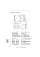 2
2 -
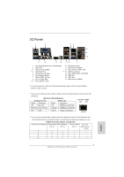 3
3 -
 4
4 -
 5
5 -
 6
6 -
 7
7 -
8
-
9
-
10
-
11
-
12
-
13
-
14
-
15
-
16
-
17
-
18
-
19
-
20
-
21
-
22
-
23
-
24
-
25
-
26
-
27
-
28
-
29
-
30
-
31
-
32
-
33
-
34
-
35
-
36
-
37
-
38
-
39
-
40
-
41
-
42
-
43
-
44
-
45
-
46
-
47
-
48
-
49
-
50
-
51
-
52
-
53
-
54
-
55
-
56
-
57
-
58
-
59
-
60
-
61
-
62
-
63
-
64
-
65
-
66
-
67
-
68
-
69
-
70
-
71
-
72
-
73
-
74
-
75
-
76
-
77
-
78
-
79
-
80
-
81
-
82
-
83
-
84
-
85
-
86
-
87
-
88
-
89
-
90
-
91
-
92
-
93
-
94
-
95
-
96
-
97
-
98
-
99
-
100
-
101
-
102
-
103
-
104
-
105
-
106
-
107
-
108
-
109
-
110
-
111
-
112
-
113
-
114
-
115
-
116
-
117
-
118
-
119
-
120
-
121
-
122
-
123
-
124
-
125
-
126
-
127
-
128
-
129
-
130
-
131
-
132
-
133
-
134
-
135
-
136
-
137
-
138
-
139
-
140
-
141
-
142
-
143
-
144
-
145
-
146
-
147
-
148
-
149
-
150
-
151
-
152
-
153
-
154
-
155
-
156
-
157
-
158
-
159
-
160
-
161
-
162
-
163
-
164
-
165
-
166
-
167
-
168
-
169
-
170
-
171
-
172
-
173
-
174
-
175
-
176
-
177
-
178
-
179
-
180
-
181
-
182
-
183
-
184
-
185
-
186
-
187
-
188
-
189
-
190
-
191
-
192
-
193
-
194
-
195
-
196
-
197
-
198
-
199
-
200
-
201
-
202
-
203
-
204
-
205
-
206
-
207
-
208
-
209
-
210
-
211
-
212
-
213
-
214
-
215
-
216
-
217
-
218
-
219
-
220
-
221
-
222
-
223
-
224
-
225
-
226
-
227
-
228
-
229
-
230
-
231
-
232
-
233
-
234
-
235
-
236
-
237
-
238
-
239
-
240
-
241
-
242
-
243
-
244
-
245
-
246
-
247
-
248
-
249
-
250
-
251
-
252
-
253
-
254
-
255
-
256
-
257
-
258
-
259
-
260
-
261
-
262
-
263
-
264
-
265
-
266
-
267
-
268
-
269
-
270
-
271
-
272
-
273
-
274
-
275
-
276
-
277
-
278
-
279
-
280
-
281
-
282
-
283
-
284
-
285
-
286
 |
 |
1
ASRock
A75 Extreme6
Motherboard
English
Copyright Notice:
No part of this installation guide may be reproduced, transcribed, transmitted, or trans-
lated in any language, in any form or by any means, except duplication of documentation
by the purchaser for backup purpose, without written consent of ASRock Inc.
Products and corporate names appearing in this guide may or may not be registered
trademarks or copyrights of their respective companies, and are used only for identi
fi
ca-
tion or explanation and to the owners’ bene
fi
t, without intent to infringe.
Disclaimer:
Speci
fi
cations and information contained in this guide are furnished for informational use
only and subject to change without notice, and should not be constructed as a commit-
ment by ASRock. ASRock assumes no responsibility for any errors or omissions that may
appear in this guide.
With respect to the contents of this guide, ASRock does not provide warranty of any kind,
either expressed or implied, including but not limited to the implied warranties or condi-
tions of merchantability or
fi
tness for a particular purpose. In no event shall ASRock, its
directors, of
fi
cers, employees, or agents be liable for any indirect, special, incidental, or
consequential damages (including damages for loss of pro
fi
ts, loss of business, loss of
data, interruption of business and the like), even if ASRock has been advised of the pos-
sibility of such damages arising from any defect or error in the guide or product.
This device complies with Part 15 of the FCC Rules. Operation is subject to the following
two conditions:
(1) this device may not cause harmful interference, and
(2) this device must accept any interference received, including interference that
may cause undesired operation.
CALIFORNIA, USA ONLY
The Lithium battery adopted on this motherboard contains Perchlorate, a toxic substance
controlled in Perchlorate Best Management Practices (BMP) regulations passed by the
California Legislature. When you discard the Lithium battery in California, USA, please
follow the related regulations in advance.
“Perchlorate Material-special handling may apply, see
www.dtsc.ca.gov/hazardouswaste/perchlorate”
ASRock Website: http://www.asrock.com
Published June 2011
Copyright
©
2011 ASRock INC. All rights reserved.