ASRock A75 Pro4/MVP User Manual
ASRock A75 Pro4/MVP Manual
 |
View all ASRock A75 Pro4/MVP manuals
Add to My Manuals
Save this manual to your list of manuals |
ASRock A75 Pro4/MVP manual content summary:
- ASRock A75 Pro4/MVP | User Manual - Page 1
A75 Pro4/MVP User Manual Version 1.0 Published February 2012 Copyright©2012 ASRock INC. All rights reserved. 1 - ASRock A75 Pro4/MVP | User Manual - Page 2
profits, loss of business, loss of data, interruption of business and the like), even if ASRock has been advised of the possibility of such damages arising from any defect or error in the manual ONLY The Lithium battery adopted on this motherboard contains Perchlorate, a toxic substance controlled in - ASRock A75 Pro4/MVP | User Manual - Page 3
1.3 Motherboard Layout Guide 20 2.6 Dual Graphics Operation Guide 24 2.7 Dual Monitor and Surround Display Features 26 2.8 ASRock Smart Remote Installation Guide 29 2.9 Jumpers Setup 30 2.10 and Operation Operation Guide 42 2.16 Driver Installation Guide 44 2.17 Installing Windows® 7 / 7 - ASRock A75 Pro4/MVP | User Manual - Page 4
Health Event Monitoring Screen 62 3.6 Boot Screen 63 3.7 Security Screen 64 3.8 Exit Screen 65 4. Software Support 66 4.1 Install Operating System 66 4.2 Support CD Information 66 4.2.1 Running Support CD 66 4.2.2 Drivers Menu 66 4.2.3 Utilities Menu 66 4.2.4 Contact Information 66 4 - ASRock A75 Pro4/MVP | User Manual - Page 5
Contents ASRock A75 Pro4/MVP Motherboard (ATX Form Factor: 12.0-in x 8.8-in, 30.5 cm x 22.4 cm) ASRock A75 Pro4/MVP Quick Installation Guide ASRock A75 Pro4/MVP Support CD 4 x Serial ATA (SATA) Data Cables (Optional) 1 x I/O Panel Shield ASRock Reminds You... To get better performance in Windows - ASRock A75 Pro4/MVP | User Manual - Page 6
Memory Expansion Slot Graphics - ATX Form Factor: 12.0-in x 8.8-in, 30.5 cm x 22.4 cm - All Solid Capacitor design - Support for Socket FM1 100W processors - 4 + 1 Power Phase Design - Supports AMD's Cool 'n' QuietTM Technology - UMI-Link GEN2 - AMD A75 FCH (Hudson-D3) - Dual Channel DDR3 Memory - ASRock A75 Pro4/MVP | User Manual - Page 7
(Realtek ALC892 Audio Codec) - Premium Blu-ray audio support - Supports THX TruStudioTM - PCIE x1 Gigabit LAN 10/100/1000 Mb/s - Realtek RTL8111E - Supports Wake-On-LAN - Supports LAN Cable Detection - Supports Energy Efficient Ethernet 802.3az - Supports PXE I/O Panel - 1 x PS/2 Mouse/Keyboard Port - ASRock A75 Pro4/MVP | User Manual - Page 8
Compliance Wake Up Events - Supports jumperfree - SMBIOS 2.3.1 Support - DRAM, VDDP, VDDR, SB Voltage Multi-adjustment Support CD - Drivers, Utilities, AntiVirus Software (Trial Version), AMD Live! Explorer, AMD Fusion, CyberLink MediaEspresso 6.5 Trial, ASRock MAGIX Multimedia Suite - OEM - ASRock A75 Pro4/MVP | User Manual - Page 9
. We are not responsible for possible damage caused by overclocking. CAUTION! 1. This motherboard supports Dual Channel Memory Technology. Before you implement Dual Channel Memory Technology, make sure to read the installation guide of memory modules on page 17 for proper installation. 2. Whether - ASRock A75 Pro4/MVP | User Manual - Page 10
Extreme Tuning Utility (AXTU). ASRock website: http://www.asrock.com 9. ASRock Instant Flash is a BIOS flash utility embedded in Flash ROM. This convenient BIOS update tool allows you to update system BIOS without entering operating systems first like MS-DOS or Windows®. With this utility, you can - ASRock A75 Pro4/MVP | User Manual - Page 11
cannot be used under Windows® OS 32-bit CPU. ASRock XFast RAM shortens the loading to extend their lifespan. 15. VIRTU Universal MVP includes the base features of Virtu Universal mode condition. To meet EuP standard, an EuP ready motherboard and an EuP ready power supply are required. According to - ASRock A75 Pro4/MVP | User Manual - Page 12
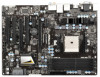
A75 Pro4/MVP Dual Graphics AUDIO CODEC Super I/O PCIE2 DX11 PCIE3 USB 3.0 CMOS BATTERY PCI1 ErP/EuP Ready XFast USB PCIE4 1 CLRCMOS1 AMD A75 FCH (Hudson-D3) Chipset SATA3_5 SATA3_4 SATA3 6Gb/s 1394a HD_AUDIO1 FRONT_1394 1 1 HDMI_SPDIF1 1 PCI2 PCI3 COM1 1 RoHS 32Mb BIOS - ASRock A75 Pro4/MVP | User Manual - Page 13
USB 2.0 Ports (USB23) LAN RJ-45 Port Central / Bass (Orange) Rear Speaker (Black) Optical SPDIF Out Port Line In (Light Blue) Front Speaker (Lime) 10 11 12 **** 13 14 15 16 17 Microphone (Pink) USB 3.0 Ports (USB01) IEEE 1394 Port (IEEE 1394) eSATA3 Connector Clear CMOS Switch (CLRCBTN) HDMI Port - ASRock A75 Pro4/MVP | User Manual - Page 14
Primary output" to use Rear Speaker, Central/Bass, and Front Speaker, or select "Realtek HDA Audio 2nd output" to use front panel audio. **** eSATA3 connector supports SATA Gen3 in cable 1M. 14 - ASRock A75 Pro4/MVP | User Manual - Page 15
, peripherals, and/or components. 1. Unplug the power cord from the wall socket before touching any component. 2. To avoid damaging the motherboard components due to static electricity, NEVER place your motherboard directly on the carpet or the like. Also remember to use a grounded wrist strap - ASRock A75 Pro4/MVP | User Manual - Page 16
Down And Lock To The Socket Corner Small The Socket Lever Triangle 2.2 Installation of CPU Fan and Heatsink After you install the CPU into this motherboard, it is necessary to install 6). For proper installation, please kindly refer to the instruction manuals of the CPU fan and the heatsink. 16 - ASRock A75 Pro4/MVP | User Manual - Page 17
2.3 Installation of Memory Modules (DIMM) This motherboard provides four 240-pin DDR3 (Double Data Rate 3) DIMM slots, and supports Dual Channel Memory Technology. For dual channel configuration, you always need to install identical (the same brand, speed, size and chip-type) DDR3 DIMM pair in the - ASRock A75 Pro4/MVP | User Manual - Page 18
matches the break on the slot. notch break notch break The DIMM only fits in one correct orientation. It will cause permanent damage to the motherboard and the DIMM if you force the DIMM into the slot at incorrect orientation. Step 3. Firmly insert the DIMM into the slot until the retaining - ASRock A75 Pro4/MVP | User Manual - Page 19
graphics cards to support CrossFireXTM function. 1. In single VGA card mode, it is recommended to install a PCI Express x16 graphics card on PCIE2 slot. 2. In CrossFireXTM mode, please install PCI Express x16 graphics cards on PCIE2 and PCIE4 slots. 3. Please connect a chassis fan to motherboard - ASRock A75 Pro4/MVP | User Manual - Page 20
3D application. Currently CrossFireXTM feature is supported with Windows® XP with Service Pack 2 / VistaTM / 7 OS. Quad CrossFireXTM feature are supported with Windows® VistaTM / 7 OS only. Please check AMD website for AMD CrossFireXTM driver updates. 1. If a customer incorrectly configures their - ASRock A75 Pro4/MVP | User Manual - Page 21
CrossFire Bridge on CrossFire Bridge Interconnects on the top of Radeon graphics cards. (CrossFire Bridge is provided with the graphics card you purchase, not bundled with this motherboard. Please refer to your graphics card vendor for details.) CrossFire Bridge or Step 3. Connect the DVI - ASRock A75 Pro4/MVP | User Manual - Page 22
utility to uninstall any previously installed Catalyst drivers prior to installation. Please check AMD website for AMD driver updates. Step 3. Step 4. Step 5. Install the required drivers to your system. For Windows® XP OS: A. AMD recommends Windows® XP Service Pack 2 or higher to be installed (If - ASRock A75 Pro4/MVP | User Manual - Page 23
feature. Step 7. You can freely enjoy the benefit of CrossFireXTM or Quad CrossFireXTM feature. * CrossFireXTM appearing here is a registered trademark of AMD Technologies Inc., and is used only for identification or explanation and to the owners' benefit, without intent to infringe. * For further - ASRock A75 Pro4/MVP | User Manual - Page 24
Dual Graphics system includes an AMD Radeon HD 65XX/64XX graphics processor and a motherboard based on an AMD A75 FCH (Hudson-D3) integrated chipset, all operating in a Windows® 7 environment. Please refer to below PCI Express graphics card support list for AMD Dual Graphics. For the future update - ASRock A75 Pro4/MVP | User Manual - Page 25
9. Click "Enable CrossFireTM" and click "Apply" to save your change. Step 10. Reboot your system. Then you can freely enjoy the benefit of Dual Graphics feature. * Dual Graphics appearing here is a registered trademark of AMD Technologies Inc., and is used only for identification or explanation and to - ASRock A75 Pro4/MVP | User Manual - Page 26
-D, D-Sub and HDMI), you can easily enjoy the benefits of dual monitor feature without installing any add-on VGA card to this motherboard. This motherboard also provides independent display controllers for DVI-D, D-Sub and HDMI to support dual VGA output so that DVI-D, D-sub and HDMI can drive same - ASRock A75 Pro4/MVP | User Manual - Page 27
-on VGA card is inserted to this motherboard. 4. Install the onboard VGA driver and the add-on PCI Express VGA card driver to your system. If you have installed the drivers already, there is no need to install them again. 5. Set up a multi-monitor display. For Windows® XP / XP 64-bit OS: Right click - ASRock A75 Pro4/MVP | User Manual - Page 28
For Windows® 7 / 7 64-bit supported on this motherboard. To use HDCP function with this motherboard, you need to adopt the monitor that supports HDCP function as well. Therefore, you can enjoy the superior display quality with high-definition HDCP encryption contents. Please refer to below instruction - ASRock A75 Pro4/MVP | User Manual - Page 29
chassis on the market. 3. The Multi-Angle CIR Receiver does not support Hot-Plug function. Please install it before you boot the system. * ASRock Smart Remote is only supported by some of ASRock motherboards. Please refer to ASRock website for the motherboard support list: http://www.asrock.com 29 - ASRock A75 Pro4/MVP | User Manual - Page 30
CMOS Jumper (CLRCMOS1) (see p.12, No. 10) Setting Default Clear CMOS Description Note: CLRCMOS1 allows you updating the BIOS, you must boot up the system first, and then shut it down before you do the clear-CMOS action. Please be noted that the password, date, time, user default profile, 1394 GUID - ASRock A75 Pro4/MVP | User Manual - Page 31
11 GND DUMMY 1 GND P+10 P-10 USB_PWR Either end of the SATA data cable can be connected to the SATA3 hard disk or the SATA3 connector on this motherboard. Besides two default USB 2.0 ports on the I/O panel, there are three USB 2.0 headers on this motherboard. Each USB 2.0 header can support two USB - ASRock A75 Pro4/MVP | User Manual - Page 32
supports Jack Sensing, but the panel wire on the chassis must support HDA to function correctly. Please follow the instruction in our manual and chassis manual activate the front mic. For Windows® XP / XP 64-bit OS: Select "Mixer". Select "Recorder". Then click "FrontMic". For Windows® 7 / 7 64-bit - ASRock A75 Pro4/MVP | User Manual - Page 33
RESET (Reset Switch): Connect to the reset switch on the chassis front panel. Press the reset switch to restart the computer if the computer freezes and fails to perform a normal restart. PLED (System Power LED): Connect to the power status indicator on the chassis front panel. The LED is on when - ASRock A75 Pro4/MVP | User Manual - Page 34
GND 1 2 3 4 Please connect the CPU fan cable to the connector and match the black wire to the ground pin. Though this motherboard provides 4-Pin CPU fan (Quiet Fan) support, the 3-Pin CPU fan still can work successfully even without the fan speed control function. If you plan to connect the 3-Pin - ASRock A75 Pro4/MVP | User Manual - Page 35
Serial port Header (9-pin COM1) (see p.12 No.30) HDMI_SPDIF Header (2-pin HDMI_SPDIF1) (see p.12 No. 31) This COM1 header supports a serial port module. HDMI_SPDIF header, providing SPDIF audio output to HDMI VGA card, allows the system to connect HDMI Digital TV/ projector/LCD devices. Please - ASRock A75 Pro4/MVP | User Manual - Page 36
2.11 Smart Switches This motherboard has three smart switches: power switch, reset switch and clear CMOS switch, allowing users to quickly turn on/off or reset the system or clear - ASRock A75 Pro4/MVP | User Manual - Page 37
Debug is used to provide code information, which makes troubleshooting even easier. Please see the diagrams below for reading the Dr. Debug codes. Status Code 0x00 0x01 0x02 0x03 0x04 loading Cache initialization Reserved for future AMI SEC error codes Microcode not found Microcode not loaded PEI - ASRock A75 Pro4/MVP | User Manual - Page 38
not installed Invalid CPU type or Speed CPU mismatch CPU self test failed or possible CPU cache error CPU micro-code is not found or micro-code update is failed Internal CPU error reset PPI is not available Reserved for future AMI error codes S3 Resume is stared (S3 Resume PPI is called by the - ASRock A75 Pro4/MVP | User Manual - Page 39
0x9F 0xA0 0xA1 0xA2 0xA3 0xA4 0xA5 Installation of the South Bridge Runtime Services CPU DXE initialization is started CPU DXE initialization (CPU module specific) CPU for future AMI DXE codes OEM DXE initialization codes Boot Device Selection (BDS) phase is started Driver connecting is started PCI - ASRock A75 Pro4/MVP | User Manual - Page 40
Codes section below) Setup Input Wait Reserved for ASL (see ASL Status Codes section below) Ready To Boot event Legacy Boot event Exit Boot Services future AMI codes OEM BDS initialization codes CPU initialization error North Bridge initialization error South Bridge initialization error Some of - ASRock A75 Pro4/MVP | User Manual - Page 41
Hard Disks Installation This motherboard adopts AMD A75 FCH (Hudson-D3) chipset that supports Serial ATA3 (SATA3) hard disks and RAID (RAID 0, RAID 1 and RAID 10) functions. You may install SATA3 hard disks on this motherboard for internal storage devices. This section will guide you to install the - ASRock A75 Pro4/MVP | User Manual - Page 42
is installed into system properly. The latest SATA3 driver is available on our support website: www.asrock.com 4. Make sure to use the SATA power cable & data cable, which are from our motherboard package. 5. Please follow below instructions step by step to reduce the risk of HDD crash or data - ASRock A75 Pro4/MVP | User Manual - Page 43
data cable to end (White) to the power supply 1x4-pin the motherboard's SATAII / SATA3 cable. connector. SATA power cable 1x4-pin power of attention, before you process the Hot Unplug: Please do follow below instruction sequence to process the Hot Unplug, improper procedure will cause the SATA3 - ASRock A75 Pro4/MVP | User Manual - Page 44
to the OS you install. 2.17.1 Installing Windows® XP / XP 64-bit With RAID Functions If you want to install Windows® XP / XP 64-bit on a RAID to [RAID]. STEP 2: Make a SATA3 Driver Diskette. (Please use USB floppy or floppy disk.) A. Insert the ASRock Support CD into your optical drive to boot - ASRock A75 Pro4/MVP | User Manual - Page 45
refer to the BIOS RAID installation guide part of the document in the following path in the Support CD: .. \ RAID Installation Guide STEP 3: Make a SATA3 Driver Diskette. Make a SATA3 driver diskette by following section 2.17.1 step 2 on page 44. STEP 4: Install Windows® 7 / 7 64-bit / VistaTM - ASRock A75 Pro4/MVP | User Manual - Page 46
on your system. At the begin- ning of Windows® setup, press F6 to install a third-party AHCI driver. When prompt- ed, insert the SATA3 driver diskette containing the AMD AHCI driver. After reading the floppy disk, the driver will be presented. Select the driver to install according to the OS you - ASRock A75 Pro4/MVP | User Manual - Page 47
) STEP 1: Set up UEFI. A. Enter UEFI SETUP UTILITY Advanced screen Storage Configuration. B. Set the "SATA Mode" option to [AHCI]. STEP 2: Install Windows® 7 / 7 64-bit / VistaTM / VistaTM 64-bit OS on your system. Using SATA3 HDDs without NCQ and Hot Plug functions (IDE mode) STEP 1: Set - ASRock A75 Pro4/MVP | User Manual - Page 48
system. The SPI Memory on the motherboard stores the UEFI SETUP UTILITY. You -Test (POST) to enter the UEFI SETUP UTILITY, otherwise, POST will continue with its test software is constantly being updated, the following UEFI setup screens OC Tweaker To set up overclocking features Advanced To set up - ASRock A75 Pro4/MVP | User Manual - Page 49
3.1.2 Navigation Keys Please check the following table for the function description of each navigation key. Navigation Key(s) Function Description / Moves cursor left or right to select Screens / Moves cursor up or down to select items + / - To change option for the selected items - ASRock A75 Pro4/MVP | User Manual - Page 50
[Manual]. The default value is [100]. Please be noted that overclocking may reduce the D-Sub resolution and cause the display abnormal situation. It is recommended to use DVI or HDMI monitor to get better performance. Spread Spectrum This item should always be [Auto] for better system stability. AMD - ASRock A75 Pro4/MVP | User Manual - Page 51
Configuration DRAM Frequency If [Auto] is selected, the motherboard will detect the memory module(s) inserted and assigns appropriate frequency CAS# Latency (tCL) Use this item to change CAS# Latency (tCL) Auto/Manual setting. The default is [Auto]. RAS# to CAS# Delay (tRCD) Use this item - ASRock A75 Pro4/MVP | User Manual - Page 52
]. Read to Precharge (tRTP) Use this item to change Read to Precharge (tRTP) Auto/Manual setting. The default is [Auto]. Four Activate Window (tFAW) Use this item to change Four Activate Window (tFAW) Auto/Manual setting. The default is [Auto]. Voltage Control DRAM Voltage Use this to select DRAM - ASRock A75 Pro4/MVP | User Manual - Page 53
to malfunction. Instant Flash Instant Flash is a UEFI flash utility embedded in Flash ROM. This convenient UEFI update tool allows you to update system UEFI without entering operating systems first like MS-DOS or Windows®. Just launch this tool and save the new UEFI file to your USB flash drive, floppy - ASRock A75 Pro4/MVP | User Manual - Page 54
The default value is [Disabled]. Cool 'n' Quiet Use this item to enable or disable AMD's Cool 'n' QuietTM technology. The default value is [Enabled]. Configuration options: [Enabled] and [Disabled]. If you install Windows® 7 / VistaTM and want to enable this function, please set this item to [Enabled - ASRock A75 Pro4/MVP | User Manual - Page 55
you to enable or disable the "Onboard HDMI HD Audio" feature. Dual Graphics This item appears only when you install AMD RADEON HD6670 / 6570 / 6450 graphics card on this motherboard. Use this to enable or disable Dual Graphics feature. If you enable this option, the primary monitor will be onboard - ASRock A75 Pro4/MVP | User Manual - Page 56
3.4.3 South Bridge Configuration Onboard HD Audio Select [Auto], [Enabled] or [Disabled] for the onboard HD Audio feature. If you select [Auto], the onboard HD Audio will be disabled when PCI Sound Card is plugged. Front Panel Select [Auto] or [Disabled] for the onboard HD Audio Front Panel. On/Off - ASRock A75 Pro4/MVP | User Manual - Page 57
]. Configuration options: [AHCI Mode], [RAID Mode] and [IDE Mode]. If you set this item to RAID mode, it is suggested to install SATA ODD driver on SATA3_5 and eSATA3 ports. SATA IDE Combined Mode This item is for SATA3_5 and eSATA3 ports. Use this item to enable or disable SATA - ASRock A75 Pro4/MVP | User Manual - Page 58
3.4.5 Super IO Configuration Serial Port Use this item to enable or disable the onboard serial port. Serial Port Address Use this item to set the address for the onboard serial port. Configuration options: [3F8 / IRQ4] and [3E8 / IRQ4]. Infrared Port Use this item to enable or disable the onboard - ASRock A75 Pro4/MVP | User Manual - Page 59
RAM Use this item to select whether to auto-detect or disable the Suspend-toRAM feature. Select [Auto] will enable this feature if the OS supports it. Check Ready Bit Use this item to enable or disable the feature Check Ready Bit. Restore on AC/Power Loss This allows you to - ASRock A75 Pro4/MVP | User Manual - Page 60
ACPI HPET table Use this item to enable or disable ACPI HPET Table. The default value is [Enabled]. Please set this option to [Enabled] if you plan to use this motherboard to submit Windows® VistaTM certification. 60 - ASRock A75 Pro4/MVP | User Manual - Page 61
A75 USB 3.0 Controller Use this item to enable or disable the use of USB 3.0 controller. Legacy USB Support Use this option to select legacy support use only under UEFI setup and Windows / Linux OS. Legacy USB 3.0 Support Use this option to enable or disable legacy support for USB 3.0 devices. The - ASRock A75 Pro4/MVP | User Manual - Page 62
hardware on your system, including the parameters of the CPU temperature, motherboard temperature, CPU fan speed, chassis fan speed, and the critical voltage the chassis fan 2 speed. Confi guration options: [Full On] and [Manual Mode]. The default is value [Full On]. Chassis Fan 3 Setting This allows - ASRock A75 Pro4/MVP | User Manual - Page 63
3.6 Boot Screen In this section, it will display the available devices on your system for you to configure the boot settings and the boot priority. Setup Prompt Timeout This shows the number of seconds to wait for setup activation key. 65535(0xFFFF) means indefi nite waiting. Bootup Num-Lock If this - ASRock A75 Pro4/MVP | User Manual - Page 64
3.7 Security Screen In this section, you may set or change the supervisor/user password for the system. For the user password, you may also clear it. 64 - ASRock A75 Pro4/MVP | User Manual - Page 65
3.8 Exit Screen Save Changes and Exit When you select this option, it will pop-out the following message, "Save configuration changes and exit setup?" Select [OK] to save the changes and exit the UEFI SETUP UTILITY. Discard Changes and Exit When you select this option, it will pop-out the following - ASRock A75 Pro4/MVP | User Manual - Page 66
install the necessary drivers to activate the devices. 4.2.3 Utilities Menu The Utilities Menu shows the applications software that the motherboard supports. Click on a specific item then follow the installation wizard to install it. 4.2.4 Contact Information If you need to contact ASRock or want to - ASRock A75 Pro4/MVP | User Manual - Page 67
HDD Larger Than 2TB This motherboard is adopting UEFI BIOS that allows Windows® OS to be installed on a large size HDD (>2TB). Please follow below procedure to install the operating system. 1. Please make sure to use Windows® VistaTM 64-bit (with SP1 or above) or Windows® 7 64-bit. 2. Press or
-
 1
1 -
 2
2 -
 3
3 -
 4
4 -
 5
5 -
 6
6 -
 7
7 -
8
-
9
-
10
-
11
-
12
-
13
-
14
-
15
-
16
-
17
-
18
-
19
-
20
-
21
-
22
-
23
-
24
-
25
-
26
-
27
-
28
-
29
-
30
-
31
-
32
-
33
-
34
-
35
-
36
-
37
-
38
-
39
-
40
-
41
-
42
-
43
-
44
-
45
-
46
-
47
-
48
-
49
-
50
-
51
-
52
-
53
-
54
-
55
-
56
-
57
-
58
-
59
-
60
-
61
-
62
-
63
-
64
-
65
-
66
-
67
 |
 |

1
A75 Pro4/MVP
User Manual
Version 1.0
Published February 2012
Copyright©2012 ASRock INC. All rights reserved.