ASRock A780GXE/128M User Manual
ASRock A780GXE/128M Manual
 |
View all ASRock A780GXE/128M manuals
Add to My Manuals
Save this manual to your list of manuals |
ASRock A780GXE/128M manual content summary:
- ASRock A780GXE/128M | User Manual - Page 1
A780GXE/128M User Manual Version 1.1 Published September 2008 Copyright©2008 ASRock INC. All rights reserved. 1 - ASRock A780GXE/128M | User Manual - Page 2
written consent of ASRock Inc. Products and corporate names appearing in this manual may or may ASRock. ASRock assumes no responsibility for any errors or omissions that may appear in this manual. With respect to the contents of this manual, ASRock adopted on this motherboard contains Perchlorate, - ASRock A780GXE/128M | User Manual - Page 3
/ HD-DVD Playback Support 11 1.4 1080p Blu-ray (BD) / HD-DVD Films Which Pass Our Lab Test 12 1.5 Motherboard Layout 13 1.6 I/O Panel .... 44 2.15 SATA / SATAII HDD Hot Plug Feature and Operation Guide ..... 45 2.16 Driver Installation Guide 47 2.17 Installing Windows® XP / XP 64-bit / VistaTM / - ASRock A780GXE/128M | User Manual - Page 4
SETUP UTILITY 52 3.1 Introduction 52 3.1.1 BIOS Menu Bar 52 3.1.2 Navigation Keys 53 3.2 Main Screen 53 3.3 Smart Exit Screen 71 4 . Software Support 72 4.1 Install Operating System 72 4.2 Support CD Information 72 4.2.1 Running Support CD 72 4.2.2 Drivers Menu 72 4.2.3 Utilities Menu - ASRock A780GXE/128M | User Manual - Page 5
information about the model you are using. www.asrock.com/support/index.asp 1.1 Package Contents 1 x ASRock A780GXE/128M Motherboard (ATX Form Factor: 12.0-in x 9.6-in, 30.5 cm x 24.4 cm) 1 x ASRock A780GXE/128M Quick Installation Guide 2 x ASRock A780GXE/128M Support CD 1 x Ultra ATA 66/100/133 IDE - ASRock A780GXE/128M | User Manual - Page 6
LAN - ATX Form Factor: 12.0-in x 9.6-in, 30.5 cm x 24.4 cm - Solid Capacitor for CPU power - Support for Socket AM2+ / AM2 processors: AMD PhenomTM FX / Phenom / Athlon 64 FX / Athlon 64 X2 Dual-Core / Athlon X2 Dual-Core / Athlon 64 / Sempron processor - Supports CPU up to 140W - AMD LIVE!TM Ready - ASRock A780GXE/128M | User Manual - Page 7
- 24 pin ATX power connector - 8 pin 12V power connector - SLI/XFIRE power connector - CD in header - Front panel audio connector - 2 x USB 2.0 headers (support 4 USB 2.0 ports) (see CAUTION 11) - 1 x USB/WiFi header (see CAUTION 12) - 8Mb AMI BIOS - AMI Legal BIOS - Supports "Plug and Play - ASRock A780GXE/128M | User Manual - Page 8
64bit with 64-bit CPU, there is no such limitation. 5. This motherboard supports ATITM CrossFireTM and Hybrid CrossFireTM technology. If you want to use CrossFireTM function, please follow the instructions on page 22 and 23 to reverse the direction of ASRock SLI/XFire Switch Card in advance. 8 - ASRock A780GXE/128M | User Manual - Page 9
requirement and the passed 1080p Blu-ray (BD) / HD-DVD films in our lab test. 8. For microphone input, this motherboard supports both stereo and mono modes. For audio output, this motherboard supports 2-channel, 4-channel, 6-channel, and 8-channel modes. Please check the table on page 14 for - ASRock A780GXE/128M | User Manual - Page 10
to spray thermal grease between the CPU and the heatsink when you install the PC system. 17. This motherboard supports ASRock AM2 Boost overclocking technology. If you enable this function in the BIOS setup, the memory performance will improve up to 12.5%, but the effect still depends on the - ASRock A780GXE/128M | User Manual - Page 11
DVD playback is only supported under Windows® VistaTM / VistaTM 64-bit OS. If you install Windows® XP / XP 64-bit OS, the function of 1080p Blu-ray (BD) / HD-DVD playback is not available, please visit our website for AMD 780G VGA driver update in the future. ASRock website http://www.asrock.com 11 - ASRock A780GXE/128M | User Manual - Page 12
ray (BD) / HD-DVD Films in Our Lab Test DVD Film Name Format Type Blu-ray SWORDFISH VC-1 DVD UNDERWORLD EVOLUTION the same format of H.264. * Above passed films are tested under below configuration. Items Configurations CPU AMD Athlon X2 3600 VGA Onboard VGA with DVI-D port Memory Dual - ASRock A780GXE/128M | User Manual - Page 13
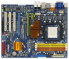
Motherboard Layout 12 3 4 5 6 24.4cm (9.6-in) 78 PS2 Mouse PS2 Keyboard AM2 )0 eSATAII_TOP SOCKET AM2 USB 2.0 AMD 780G Chipset PCIE2 PCI Express 2.0 Super I/O AUDIO CODEC USB/WIFI HDMI_SPDIF1 1 HD_AUDIO1 1 CD1 PCIE3 A780GXE/128M PCI1 PCI2 RoHS RAID 8Mb BIOS AMD 9 ATX Power SLI/ - ASRock A780GXE/128M | User Manual - Page 14
1.6 I/O Panel 1 2 34 5 6 9 7 10 8 11 16 15 14 1 PS/2 Mouse Port (Green) 2 VGA/D-Sub Port 3 USB 2.0 Ports (USB45) 4 IEEE 1394 Port * 5 LAN RJ-45 Port 6 Side Speaker (Gray) 7 Rear Speaker (Black) 8 Central / Bass (Orange) 13 12 9 ** 10 11 12 13 14 15 16 Line In (Light Blue) Front - ASRock A780GXE/128M | User Manual - Page 15
, peripherals, and/or components. 1. Unplug the power cord from the wall socket before touching any component. 2. To avoid damaging the motherboard components due to static electricity, NEVER place your motherboard directly on the carpet or the like. Also remember to use a grounded wrist strap - ASRock A780GXE/128M | User Manual - Page 16
Triangle To The Socket Corner Small Triangle STEP 4: Push Down And Lock The Socket Lever 2.2 Installation of CPU Fan and Heatsink After you install the CPU into this motherboard, it is For proper installation, please kindly refer to the instruction manuals of the CPU fan and the heatsink. 16 - ASRock A780GXE/128M | User Manual - Page 17
2.3 Installation of Memory Modules (DIMM) This motherboard provides four 240-pin DDR2 (Double Data Rate 2) DIMM slots, and supports Dual Channel Memory Technology. For dual channel configuration, you always need to install identical (the same brand, speed, size and chip-type) DDR2 DIMM pair - ASRock A780GXE/128M | User Manual - Page 18
matches the break on the slot. notch break notch break The DIMM only fits in one correct orientation. It will cause permanent damage to the motherboard and the DIMM if you force the DIMM into the slot at incorrect orientation. Step 3. Firmly insert the DIMM into the slot until the retaining - ASRock A780GXE/128M | User Manual - Page 19
There are 3 PCI slots and 3 PCI Express slots on this motherboard. PCI Slots: PCI slots are used to install expansion cards that Express graphics cards to support CrossFireTM function. PCIE2 / PCIE3 / SLI/XFire Switch Card Retention Slot Configurations PCIE2 Slot PCIE3 Slot SLI/XFire Switch Card - ASRock A780GXE/128M | User Manual - Page 20
innovative interconnect mechanism, CrossFireTM enables the highest possible level of performance and image quality in any 3D application. Currently CrossFireTM feature is supported with Windows® XP with Service Pack 2 and VistaTM OS. Please check AMD website for ATITM CrossFireTM driver updates. 20 - ASRock A780GXE/128M | User Manual - Page 21
Ready motherboard, a CrossFireTM Edition graphics card and a compatible standard Radeon (CrossFireTM Ready) graphics card from the same series, or two CrossFireTM Ready cards. This applies to cards from ATITM or any of its partners. Please refer to below table for CrossFireTM VGA card support - ASRock A780GXE/128M | User Manual - Page 22
to perform the benefit of CrossFireTM feature. Step 2. There is one ASRock SLI/XFire Switch Card factory-mounted on this motherboard. This card served as a switch between the default mode (x16) and CrossFire mode (x8 / x8). ASRock SLI/XFire Switch Card is factory-mounted with its default mode (x16 - ASRock A780GXE/128M | User Manual - Page 23
on CrossFireTM Bridge Interconnects on the top of Radeon graphics cards. (CrossFireTM Bridge is provided with the graphics card you purchase, not bundled with this motherboard. Please refer to your graphics card vendor for details.) CrossFireTM Bridge 23 - ASRock A780GXE/128M | User Manual - Page 24
this utility to uninstall any previously installed Catalyst drivers prior to installation. Please check AMD website for ATITM driver updates. Step 12. Install the required drivers to your system. For Windows® XP OS: A. ATITM recommends Windows® XP Service Pack 2 or higher to be installed (If you - ASRock A780GXE/128M | User Manual - Page 25
is used only for identification or explanation and to the owners' benefit, without intent to infringe. * For further information of ATITM CrossFireTM technology, please check AMD website for updates and details. 25 - ASRock A780GXE/128M | User Manual - Page 26
3450 series graphics processor and a motherboard based on an AMD 780G integrated chipset, all operating in a Windows® VistaTM environment. Please refer to below PCI Express graphics card support list for ATITM Hybrid CrossFireXTM. For the future update of more compatible PCI Express graphics - ASRock A780GXE/128M | User Manual - Page 27
used only for identification or explanation and to the owners' benefit, without intent to infringe. * For further information of ATITM Hybrid CrossFireXTM technology, please check AMD website for up dates and details. 27 - ASRock A780GXE/128M | User Manual - Page 28
after your system boots. If you haven't installed onboard VGA driver yet, please install onboard VGA driver from our support CD to your system and restart your computer. Then you can start to use dual monitor function on this motherboard. When you playback HDCP-protected video from Blu-ray (BD - ASRock A780GXE/128M | User Manual - Page 29
the instructions on page 22 and 23 to reverse the direction of ASRock SLI/ BIOS setup, the default value of "Share Memory", [Auto], will disable VGA/D-Sub function when the add-on VGA card is inserted to this motherboard. 5. Install the onboard VGA driver and the add-on PCI Express VGA card driver - ASRock A780GXE/128M | User Manual - Page 30
function is supported on this motherboard. To use HDCP function with this motherboard, you need to adopt the monitor that supports HDCP function as well. Therefore, you can enjoy the superior display quality with high-definition HDCP encryption contents. Please refer to below instruction for more - ASRock A780GXE/128M | User Manual - Page 31
short pin2 and pin3 on CLRCMOS1 for 5 seconds. However, please do not clear the CMOS right after you update the BIOS. If you need to clear the CMOS when you just finish updating the BIOS, you must boot up the system first, and then shut it down before you do the clear-CMOS action - ASRock A780GXE/128M | User Manual - Page 32
to the motherboard connect the black end to the IDE devices 80-conductor ATA 66/100/133 cable Note: Please refer to the instruction of your SATAII_4 SATAII_3 SATAII_6 SATAII_5 These six Serial ATAII (SATAII) connectors support SATAII or SATA hard disk for internal storage devices. The current - ASRock A780GXE/128M | User Manual - Page 33
USB 2.0 ports on the I/O panel, there are two USB 2.0 headers on this motherboard. Each USB 2.0 header can support two USB 2.0 ports. This header can be used to support 2 USB 2.0 ports. It can also be used to support WiFi+AP function with ASRock WiFi-802. 11g or WiFi-802.11n module, an easy-to-use - ASRock A780GXE/128M | User Manual - Page 34
supports Jack Sensing, but the panel wire on the chassis must support HDA to function correctly. Please follow the instruction in our manual and chassis manual need to connect them for AC'97 audio panel. E. Enter BIOS Setup Utility. Enter Advanced Settings, and then select Chipset Configuration. - ASRock A780GXE/128M | User Manual - Page 35
fan (Quiet Fan) support, the 3-Pin CPU fan still can work successfully even without the fan speed control function. If you plan to connect the 3-Pin CPU fan to the CPU fan connector on this motherboard, please connect it to Pin 1-3. Pin 1-3 Connected 3-Pin Fan Installation ATX Power Connector (24 - ASRock A780GXE/128M | User Manual - Page 36
motherboard provides 8-pin ATX 12V power 4 8 connector, it can still work if you adopt a traditional 4-pin ATX 12V power supply. To use the 4-pin ATX ATX 12V Power Supply Installation SLI/XFIRE Power Connector (4-pin SLI/XFIRE_PWR1) (see p.13 No. 39) SLI this motherboard at the same time. - ASRock A780GXE/128M | User Manual - Page 37
the HDMI_SPDIF connector of HDMI VGA card to this header. Please connect the black end (A) of HDMI_SPDIF cable to the HDMI_SPDIF header on the motherboard. Then connect the white end (B or C) of HDMI_SPDIF cable to the HDMI_SPDIF connector of HDMI VGA card. A. black end +5V SPDIFOUT GND blue black - ASRock A780GXE/128M | User Manual - Page 38
ready motherboard with a HDMI_SPDIF header. This motherboard motherboard, please carefully follow motherboard. For the proper installation of HDMI VGA card, please refer to the installation guide motherboard. Make sure to correctly connect the HDMI_SPDIF cable to the motherboard motherboard user manual - ASRock A780GXE/128M | User Manual - Page 39
eSATAII Interface Introduction What is eSATAII? This motherboard supports eSATAII interface, the external SATAII specification. . 2. If you set "SATA Operation Mode" option in BIOS setup to IDE mode, Hot Plug function is not supported with eSATAII devices. If you still want to use eSATAII function - ASRock A780GXE/128M | User Manual - Page 40
How to install eSATAII? SATAII_6 eSATAII_TOP 1. In order to enable the eSATAII port of the I/O shield, you need to connect the orange SATAII connector (SATAII_6; see p.13 No.15) and the eSATAII connector (eSATAII_TOP; see p.13 No.1) with a SATA data cable first. Connect the SATA data cable - ASRock A780GXE/128M | User Manual - Page 41
Comparison between eSATAII and other devices IEEE 1394 USB 2.0 SATA eSATAII/SATAII 400Mb/s 480Mb/s 1.5Gb/s (1500Mb/s) 3.0Gb/s (3000Mb/s) 41 - ASRock A780GXE/128M | User Manual - Page 42
guide. Some default setting of SATAII hard disks may not be at SATAII mode, which operate with the best performance. In order to enable SATAII function, please follow the below instruction 's website for details: http://www.hitachigst.com/hdd/support/download.htm The above examples are just for your - ASRock A780GXE/128M | User Manual - Page 43
adopts AMD SB700 south bridge chipset that supports Serial ATA (SATA) / Serial ATAII (SATAII) hard disks and RAID (RAID 0, RAID 1, RAID 10 and JBOD) functions. You may install SATA / SATAII hard disks on this motherboard for internal storage devices. This section will guide you to install - ASRock A780GXE/128M | User Manual - Page 44
Hot Plug and Hot Swap Functions for SATA / SATAII HDDs This motherboard supports Hot Plug and Hot Swap functions for SATA / SATAII Devices in RAID / AHCI mode. AMD SB700 south bridge chipset provides hardware support for Advanced Host controller Interface (AHCI), a new programming interface for SATA - ASRock A780GXE/128M | User Manual - Page 45
is installed into system properly. The latest SATA / SATAII driver is available on our support website: www.asrock.com 4. Make sure to use the SATA power cable & data cable, which are from our motherboard package. 5. Please follow below instructions step by step to reduce the risk of HDD crash or - ASRock A780GXE/128M | User Manual - Page 46
cable to (White) to the power supply 1x4-pin cable. the motherboard's SATAII connector. SATA power cable 1x4-pin power connector (White) Step attention, before you process the Hot Unplug: Please do follow below instruction sequence to process the Hot Unplug, improper procedure will cause the SATA - ASRock A780GXE/128M | User Manual - Page 47
Enter BIOS SETUP UTILITY Advanced screen IDE Configuration. B. Set the "SATA Operation Mode" option to [RAID]. STEP 2: Make a SATA / SATAII Driver Diskette. A. Insert the ASRock Support CD into your optical drive to boot your system. (There are two ASRock Support CD in the motherboard gift - ASRock A780GXE/128M | User Manual - Page 48
CD into your optical drive, and click the "Load Driver" button on the left on the bottom to load the AMD RAID drivers. AMD RAID drivers are in the following path in our Support CD: (There are two ASRock Support CD in the motherboard gift box pack, please choose the one for Windows® VistaTM - ASRock A780GXE/128M | User Manual - Page 49
BIOS first. Then, please set the RAID configuration by using the Windows RAID installation guide in the following path in the Support CD: .. \ RAID Installation Guide is not correspondent to the SATAII port naming rule (SATAII_1 to SATAII_6) on this motherboard. 2.18.1 Installing Windows® XP / - ASRock A780GXE/128M | User Manual - Page 50
Driver" button on the left on the bottom to load the AMD AHCI drivers. AMD AHCI drivers are in the following path in our Support CD: (There are two ASRock Support CD in the motherboard and Hot Plug functions STEP 1: Set up BIOS. A. Enter BIOS SETUP UTILITY Advanced screen IDE Configuration. B. - ASRock A780GXE/128M | User Manual - Page 51
19 Untied Overclocking Technology This motherboard supports Untied Overclocking Technology, which means during overclocking, FSB enjoys better margin due to fixed PCI / PCIE buses. Before you enable Untied Overclocking function, please enter "Overclock Mode" option of BIOS setup to set the selection - ASRock A780GXE/128M | User Manual - Page 52
motherboard stores the BIOS SETUP UTILITY. You may run the BIOS SETUP UTILITY when you start up the computer. Please press during the Power-On-Self-Test (POST) to enter the BIOS back on. Because the BIOS software is constantly being updated, the following BIOS setup screens and descriptions are - ASRock A780GXE/128M | User Manual - Page 53
System Overview System Time System Date [17:00:09] [Mon 07/04/2008] BIOS Version : A780GXE/128M P1.0 Processor Type : AMD Athlon(tm) 64 X2 Dual Core Processor 4800+ (64bit) Processor Speed : 2400MHz Microcode Update : 40F32/62 L1 Cache Size : 256KB L2 Cache Size : 2048KB Total Memory DDRII1 - ASRock A780GXE/128M | User Manual - Page 54
will pop-out the following message, "Save configuration changes and exit setup?" Select [OK] to save the changes and exit the BIOS SETUP UTILITY. Load BIOS Defaults Load BIOS default values for all the setup questions. F9 key can be used for this operation. Load Performance Setup Default (IDE/SATA - ASRock A780GXE/128M | User Manual - Page 55
Configuration BIOS SETUP UTILITY Advanced CPU Configuration AM2 Boost will be left at the rated frequency/voltage. If Manual, multiplier and voltage will be set based on User AM2 Boost This option appears only when you adopt AM2 CPU. If you set this option to [Enabled], you will enable ASRock AM2 - ASRock A780GXE/128M | User Manual - Page 56
Cool 'n' Quiet Use this item to enable or disable AMD's Cool 'n' QuietTM technology. The default value is [ Machine This option appears only when you adopt AM2 CPU. When this option is set to [Enabled [Auto] by default. If it is set to [Manual], you may adjust the value of Processor Frequency and - ASRock A780GXE/128M | User Manual - Page 57
BIOS SETUP UTILITY Advanced CPU Configuration AM2 Boost Overclock Mode CPU Frequency (MHz) PCIE Frequency (MHz AM2 CPU. This item will show when "Multiplier/Voltage Change" is set to [Manual]; otherwise, it will be hidden. The range of the value depends on the CPU you adopt on this motherboard. - ASRock A780GXE/128M | User Manual - Page 58
CPU Voltage This option appears only when you adopt Phenom CPU. It allows you to adjust the value of CPU voltage. However, for safety and system stability, it is not recommended to adjust the value of this item. NB Frequency Multiplier This option appears only when you adopt Phenom CPU. However, for - ASRock A780GXE/128M | User Manual - Page 59
], [2CLK], [3CLK], [4CLK], [5CLK], [6CLK], [7CLK], [8CLK] and [9CLK]. The default value is [Auto]. TWRRD This option appears only when you adopt AM2 CPU. Use this to adjust TWRRD values. Configuration options: [Auto], [0CLK], [1CLK], [2CLK] and [3CLK]. The default value is [Auto]. TWRWR This option - ASRock A780GXE/128M | User Manual - Page 60
3.4.2 Chipset Configuration BIOS SETUP UTILITY Advanced Chipset Settings OnBoard HD Audio Front Panel OnBoard LAN OnBoard IEEE 1394 Primary Graphics Adapter [Auto] [Auto] [Enabled] [Enabled] [PCI] Internal Graphics - ASRock A780GXE/128M | User Manual - Page 61
Graphics Mode" to [SIDEPORT] or [UMA+SIDEPORT]. OnBoard HDMI HD Audio This allows you to enable or disable the onboard HDMI HD Audio in AMD 780G. GFX Engine Clock Override This allows you to enable or disable the GFX Engine Clock Override feature. GFX Engine Clock This option only appears when - ASRock A780GXE/128M | User Manual - Page 62
3.4.3 ACPI Configuration BIOS SETUP UTILITY Advanced ACPI Settings Suspend To RAM Repost Video on STR Resume Check Ready Bit Away Mode Support Restore on AC / Power Loss Ring-In Power On PCI Devices Power On PS / 2 Keyboard Power On RTC Alarm Power On ACPI HPET Table [Auto] [ - ASRock A780GXE/128M | User Manual - Page 63
Enabled] if you plan to use this motherboard to submit Windows® VistaTM certification. 3.4.4 IDE Configuration BIOS SETUP UTILITY Advanced IDE Configuration Onboard SATA " as the example in the following instruction, which can be applied to the configurations of "IDE1 Slave" as well. 63 - ASRock A780GXE/128M | User Manual - Page 64
BIOS SETUP UTILITY Advanced IDE Master Device Vendor Size LBA Mode Block Mode PIO Mode Async DMA Ultra DMA S.M.A.R.T. :Hard Disk :MAXTOR 6L080J4 :80.0 GB :Supported :16Sectors :4 :MultiWord DMA-2 :Ultra DMA-6 :Supported selecting the hard disk information into BIOS, use a disk utility, such as - ASRock A780GXE/128M | User Manual - Page 65
], [Enabled]. 32Bit Data Transfer Use this item to enable 32-bit access to maximize the IDE hard disk data transfer rate. 3.4.5 PCIPnP Configuration BIOS SETUP UTILITY Advanced Advanced PCI / PnP Settings PCI Latency Timer PCI IDE BusMaster [32] [Enabled] Value in units of PCI clocks for PCI - ASRock A780GXE/128M | User Manual - Page 66
SETUP UTILITY Advanced Configure Super IO Chipset OnBoard Floppy Controller Serial Port Address Infrared Port Address [Enabled] [3F8 / IRQ4] [Disabled] Allow BIOS to Enable or Disable Floppy Controller. +F1 F9 F10 ESC Select Screen Select Item Change Option General Help Load Defaults Save and - ASRock A780GXE/128M | User Manual - Page 67
this item to enable or disable the USB 2.0 support. Legacy USB Support Use this option to select legacy support for USB devices. There are four configuration options: [Enabled], [Auto], [Disabled] and [BIOS Setup Only]. The default value is [BIOS Setup Only]. Please refer to below descriptions for - ASRock A780GXE/128M | User Manual - Page 68
the status of the hardware on your system, including the parameters of the CPU temperature, motherboard temperature, CPU fan speed, chassis fan speed, and the critical voltage. BIOS SETUP UTILITY Main Smart Advanced H/W Monitor Boot Security Exit Hardware Health Event Monitoring CPU Temperature - ASRock A780GXE/128M | User Manual - Page 69
system for you to configure the boot settings and the boot priority. BIOS SETUP UTILITY Main Smart Advanced H/W Monitor Boot Security Exit Boot Settings Boot : [Auto], [PCIE2.0 Revolution], [Scenery] and [ASRock]. The default value is [Auto]. Currently, the option [Auto] is set to Aircraft. 69 - ASRock A780GXE/128M | User Manual - Page 70
section, you may set or change the supervisor/user password for the system. For the user password, you may also clear it. BIOS SETUP UTILITY Main Smart Advanced H/W Monitor Boot Security Exit Security Settings Supervisor Password : Not Installed User Password : Not Installed Change Supervisor - ASRock A780GXE/128M | User Manual - Page 71
and exit setup?" Select [OK] to save the changes and exit the BIOS SETUP UTILITY. Discard Changes and Exit When you select this option, it message, "Discard changes and exit setup?" Select [OK] to exit the BIOS SETUP UTILITY without saving any changes. Discard Changes When you select this option - ASRock A780GXE/128M | User Manual - Page 72
install the necessary drivers to activate the devices. 4.2.3 Utilities Menu The Utilities Menu shows the applications software that the motherboard supports. Click on a specific item then follow the installation wizard to install it. 4.2.4 Contact Information If you need to contact ASRock or want to
-
 1
1 -
 2
2 -
 3
3 -
 4
4 -
 5
5 -
 6
6 -
 7
7 -
8
-
9
-
10
-
11
-
12
-
13
-
14
-
15
-
16
-
17
-
18
-
19
-
20
-
21
-
22
-
23
-
24
-
25
-
26
-
27
-
28
-
29
-
30
-
31
-
32
-
33
-
34
-
35
-
36
-
37
-
38
-
39
-
40
-
41
-
42
-
43
-
44
-
45
-
46
-
47
-
48
-
49
-
50
-
51
-
52
-
53
-
54
-
55
-
56
-
57
-
58
-
59
-
60
-
61
-
62
-
63
-
64
-
65
-
66
-
67
-
68
-
69
-
70
-
71
-
72
 |
 |
1
A780GXE/128M
User Manual
Version 1.
1
Published
September
2008
Copyright©2008 ASRock INC. All rights reserved.