ASRock AD2550-ITX User Manual
ASRock AD2550-ITX Manual
 |
View all ASRock AD2550-ITX manuals
Add to My Manuals
Save this manual to your list of manuals |
ASRock AD2550-ITX manual content summary:
- ASRock AD2550-ITX | User Manual - Page 1
AD2550-ITX User Manual Version 1.0 Published March 2013 Copyright©2013 ASRock INC. All rights reserved. 1 - ASRock AD2550-ITX | User Manual - Page 2
any form or by any means, except duplication of documentation by the purchaser for backup purpose, without written consent of ASRock Inc. Products and corporate names appearing in this manual may or may not be registered trademarks or copyrights of their respective companies, and are used only for - ASRock AD2550-ITX | User Manual - Page 3
Serial ATA2 (SATA2) Hard Disks Installation 23 2.9 Hot Plug and Hot Swap Functions for SATA / SATA2 HDDs 23 2.10 Driver Installation Guide 24 2.11 Installing Windows® 7 on SATA / SATAII HDDs .......... 24 3 UEFI SETUP UTILITY 25 3.1 Introduction 25 3.1.1 UEFI Menu Bar 25 3.1.2 Navigation Keys - ASRock AD2550-ITX | User Manual - Page 4
4 Software Support 39 4.1 Install Operating System 39 4.2 Support CD Information 39 4.2.1 Running Support CD 39 4.2.2 Drivers Menu 39 4.2.3 Utilities Menu 39 4.2.4 Contact Information 39 4 - ASRock AD2550-ITX | User Manual - Page 5
about the model you are using. www.asrock.com/support/index.asp 1.1 Package Contents ASRock AD2550-ITX Motherboard (Mini-ITX Form Factor: 6.7-in x 6.7-in, 17.0 cm x 17.0 cm) ASRock AD2550-ITX Quick Installation Guide ASRock AD2550-ITX Support CD 2 x Serial ATA (SATA) Data Cables (Optional - ASRock AD2550-ITX | User Manual - Page 6
Audio LAN Rear Panel I/O - Mini-ITX Form Factor: 6.7-in x 6.7-in, 17.0 cm x 17.0 cm - All Solid Capacitor design - Intel® Dual-Core AtomTM Processor D2550 (1.86 GHz) - Supports Hyper-Threading Technology - Southbridge: Intel® NM10 Express - 2 x DDR3 SO-DIMM slots - Supports DDR3 1066/800 non-ECC - ASRock AD2550-ITX | User Manual - Page 7
- CPU/Chassis Quiet Fan - Voltage Monitoring: +12V, +5V, +3.3V, CPU Vcore OS - Microsoft® Windows® 7 32-bit compliant * Due to lack of Intel® 64-bit VGA driver support, this motherboard does not support 64-bit OS. Certifications - FCC, CE, WHQL - ErP/EuP Ready (ErP/EuP ready power supply is - ASRock AD2550-ITX | User Manual - Page 8
involved with overclocking, including adjusting the setting in the BIOS, applying Untied Overclocking Technology, or using the third-party the actual memory size may be less than 4GB for the reservation for system usage under Windows® OS. 2. You can choose to use two of the three monitors only. D-Sub - ASRock AD2550-ITX | User Manual - Page 9
startup process, Instant Boot allows you to enter your Windows® desktop in a few seconds. ASRock Instant Flash ASRock Instant Flash is a BIOS flash utility embedded in Flash ROM. This convenient BIOS update tool allows you to update system BIOS without entering operating systems first like MSDOS or - ASRock AD2550-ITX | User Manual - Page 10
Utility (AXTU). It fully utilizes the memory space that cannot be used under Windows® OS 32-bit CPU. ASRock XFast RAM shortens the loading time of previously visited websites, making web surfing faster 3.5mm audio cable (optional) that ensures users the most convenient computing environment. 10 - ASRock AD2550-ITX | User Manual - Page 11
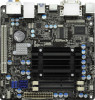
Bottom: Optical SPDIF LAN PHY CMOS Battery 16Mb BIOS Top: Center: Bottom: MIC IN 1 AD2550-ITX AUDIO HD_AUDIO1 CODEC PCI1 SATAII_1 SATAII_2 1 1 Header (USB8_9, Blue) (HD_AUDIO1, White) 10 Infrared Module Header (IR1) 20 Intel NM10 Express Chip 11 System Panel Header (PANEL1, White) - ASRock AD2550-ITX | User Manual - Page 12
USB 2.0 Ports 2 D-Sub Port * 3 LAN RJ-45 Port 4 Central / Bass (Orange) 5 Rear Speaker (Black) 6 Optical SPDIF Out Port 7 Line In (Light Blue) ** 8 9 10 11 12 13 14 Front Speaker (Lime) Microphone (Pink) USB 2.0 Ports USB 3.0 Ports (ASMedia ASM1042) HDMI Port DVI-D Port PS/2 Keyboard Port (Purple - ASRock AD2550-ITX | User Manual - Page 13
Chapter 2: Installation This is a Mini-ITX form factor (6.7" x 6.7", 17.0 x 17.0 cm) motherboard. Before you install the motherboard, study the configuration of your chassis to ensure that the motherboard fits into it. - ASRock AD2550-ITX | User Manual - Page 14
2.3 Installation of Memory Modules (SO-DIMM) AD2550-ITX motherboard provides two 204-pin DDR3 (Double Data Rate 3) SODIMM slots. 1. It is not allowed to install a DDR or DDR2 memory module into DDR3 slot; - ASRock AD2550-ITX | User Manual - Page 15
2.4 Expansion Slot (PCI Slot) There is 1 PCI slot on this motherboard. PCI slot: The PCI slot is used to install expansion card that has the 32-bit PCI interface. Installing an expansion card Step 1. Before installing the expansion card, please make sure that the power supply is switched off or - ASRock AD2550-ITX | User Manual - Page 16
or connect HDMI monitor cable to HDMI port on the I/O panel. D-Sub port DVI-D port HDMI port 2. If you have installed onboard VGA driver from our support CD to your system already, you can freely enjoy the benefits of dual monitor function after your system boots. If you haven't installed onboard - ASRock AD2550-ITX | User Manual - Page 17
function with this motherboard, you need to adopt the monitor that supports HDCP function as well. Therefore, you can enjoy the superior display quality with high-definition HDCP encryption contents. Please refer to below instruction for more details about HDCP function. What is HDCP? HDCP stands - ASRock AD2550-ITX | User Manual - Page 18
2.6 Jumpers Setup The illustration shows how jumpers are setup. When the jumper cap is placed on pins, the jumper is "Short". If no jumper cap is placed on pins, the jumper is "Open". The illustration shows a 3-pin jumper whose pin1 and pin2 are "Short" when jumper cap is placed on these 2 pins. - ASRock AD2550-ITX | User Manual - Page 19
motherboard! Serial ATA2 Connectors (SATAII_1: see p.11, No. 16) (SATAII_2: see p.11, No. 8) SATAII_1 SATAII_2 These two Serial ATA2 (SATA2) connectors support SATA data cables for internal storage devices. The current SATA2 interface allows up to 3.0 Gb/s data transfer rate. Serial ATA (SATA - ASRock AD2550-ITX | User Manual - Page 20
(5-pin IR1) (see p.11 No. 10) IRTX +5VSB DUMMY 1 GND IRRX This header supports an optional wireless transmitting and receiving infrared supports Jack Sensing, but the panel wire on the chassis must support HDA to function correctly. Please follow the instruction in our manual and chassis manual - ASRock AD2550-ITX | User Manual - Page 21
PLED (System Power LED): Connect to the power status indicator on the chassis front panel. The LED is on when the system is operating. The LED keeps blinking when the system is in S1 sleep state. The LED is off when the system is in S3/S4 sleep state or powered off (S5). HDLED (Hard Drive Activity - ASRock AD2550-ITX | User Manual - Page 22
is an interface for print port cable that allows convenient connection of printer devices. Serial port Header (9-pin COM1) (see p.11 No. 2) This COM1 header supports a serial port module. 22 - ASRock AD2550-ITX | User Manual - Page 23
(SATAII) Hard Disks Installation This motherboard adopts Intel® NM10 Express chipset that supports Serial ATA (SATA) / Serial ATAII (SATAII) hard disks. You may install SATA / SATAII hard disks on this motherboard for internal storage devices. This section will guide you to install the SATA / SATAII - ASRock AD2550-ITX | User Manual - Page 24
10 Driver Installation Guide To install the drivers to your system, please insert the support CD to your optical drive first. Then, the drivers compatible to your system can be auto-detected and listed on the support CD driver Mode" to [AHCI]. STEP 2: Install Windows® 7 OS on your system. Storage - ASRock AD2550-ITX | User Manual - Page 25
SETUP UTILITY when you start up the computer. Please press or during the Power-On-Self-Test (POST) to enter the UEFI SETUP UTILITY, otherwise, POST will continue with its test routines. If you wish to enter the UEFI SETUP UTILITY after POST, restart the system by pressing + - ASRock AD2550-ITX | User Manual - Page 26
3.1.2 Navigation Keys Please check the following table for the function description of each navigation key. Navigation Key(s) Function Description / Moves cursor left or right to select Screens / Moves cursor up or down to select items + / - To change option for the selected items - ASRock AD2550-ITX | User Manual - Page 27
utility embedded in Flash ROM. This convenient UEFI update tool allows you to update system UEFI without entering operating systems first like MS-DOS or Windows®. Just launch this tool and save the new UEFI file to your USB flash drive, floppy disk or hard drive, then you can update your - ASRock AD2550-ITX | User Manual - Page 28
feature, it requires a computer system with an Intel processor that supports Hyper-Threading technology and an operating system that includes optimization for this technology, such as Microsoft® Windows® 7. Set to [Enabled] if using Microsoft® Windows® 7. No-Excute Memory Protection No-Execution (NX - ASRock AD2550-ITX | User Manual - Page 29
or disable ACPI HPET Table. The default value is [Enabled]. Please set this option to [Enabled] if you plan to use this motherboard to submit Windows® certification. Restore on AC/Power Loss This allows you to set the power state after an unexpected AC/power loss. If [Power Off] is selected - ASRock AD2550-ITX | User Manual - Page 30
Use this to select SATA2 mode. Configuration options: [IDE Mode], [AHCI Mode] and [Disabled]. The default value is [IDE Mode]. AHCI (Advanced Host Controller Interface) supports NCQ and other new features that will improve SATA disk performance but IDE mode does not have these advantages. 30 - ASRock AD2550-ITX | User Manual - Page 31
]. LPT1 Port Address Use this item to set the address for the onboard parallel port. Configuration options: [Auto], [IO=378h; IRQ=5; DMA=3], [IO=378h; IRQ=5, 6, 7, 9, 10, 11, 12; DMA=1, 3] and [IO=278h; IRQ - ASRock AD2550-ITX | User Manual - Page 32
whether to auto-detect or disable the Suspend-toRAM feature. Select [Auto] will enable this feature if the OS supports it. Deep S5 Mobile platforms support Deep S5 in DC only and desktop platforms support Deep S5 in AC only. The default value is [Auto]. PS/2 Keyboard Power On Use this item to - ASRock AD2550-ITX | User Manual - Page 33
issue, it is recommended to select [Disabled] to enter OS. [UEFI Setup Only] - USB devices are allowed to use only under UEFI setup and Windows / Linux OS. Legacy USB 3.0 Support Use this option to enable or disable legacy support for USB 3.0 devices. The default value is [Disabled]. 33 - ASRock AD2550-ITX | User Manual - Page 34
3.3.7 Voltage Configuration DRAM Voltage Use this to select DRAM Voltage. The default value is [Auto]. +1.05V Voltage Use this to select +1.05V Voltage. The default value is [Auto]. +1.5V Voltage Use this to select +1.5V Voltage. The default value is [Auto]. 34 - ASRock AD2550-ITX | User Manual - Page 35
3.4 Hardware Health Event Monitoring Screen In this section, it allows you to monitor the status of the hardware on your system, including the parameters of the CPU temperature, motherboard temperature, CPU fan speed, chassis fan speed, and the critical voltage. CPU Fan Setting This allows you to - ASRock AD2550-ITX | User Manual - Page 36
3.5 Boot Screen In this section, it will display the available devices on your system for you to configure the boot settings and the boot priority. Setup Prompt Timeout This shows the number of seconds to wait for setup activation key. 65535(0XFFFF) means indefinite waiting. Bootup Num-Lock If this - ASRock AD2550-ITX | User Manual - Page 37
3.6 Security Screen In this section, you may set or change the supervisor/user password for the system. For the user password, you may also clear it. 37 - ASRock AD2550-ITX | User Manual - Page 38
3.7 Exit Screen Save Changes and Exit When you select this option, it will pop-out the following message, "Save configuration changes and exit setup?" Select [OK] to save the changes and exit the UEFI SETUP UTILITY. Discard Changes and Exit When you select this option, it will pop-out the following - ASRock AD2550-ITX | User Manual - Page 39
install the necessary drivers to activate the devices. 4.2.3 Utilities Menu The Utilities Menu shows the applications software that the motherboard supports. Click on a specific item then follow the installation wizard to install it. 4.2.4 Contact Information If you need to contact ASRock or want to
-
 1
1 -
 2
2 -
 3
3 -
 4
4 -
 5
5 -
 6
6 -
 7
7 -
8
-
9
-
10
-
11
-
12
-
13
-
14
-
15
-
16
-
17
-
18
-
19
-
20
-
21
-
22
-
23
-
24
-
25
-
26
-
27
-
28
-
29
-
30
-
31
-
32
-
33
-
34
-
35
-
36
-
37
-
38
-
39
 |
 |

1
AD2550-ITX
User Manual
Version 1.0
Published March 2013
Copyright©2013 ASRock INC. All rights reserved.