ASRock ALiveNF4G-DVI User Manual
ASRock ALiveNF4G-DVI Manual
 |
View all ASRock ALiveNF4G-DVI manuals
Add to My Manuals
Save this manual to your list of manuals |
ASRock ALiveNF4G-DVI manual content summary:
- ASRock ALiveNF4G-DVI | User Manual - Page 1
ALiveNF4G-DVI User Manual Version 1.1 Published August 2006 Copyright©2006 ASRock INC. All rights reserved. 1 - ASRock ALiveNF4G-DVI | User Manual - Page 2
, in any form or by any means, except duplication of documentation by the purchaser for backup purpose, without written consent of ASRock Inc. Products and corporate names appearing in this manual may or may not be registered trademarks or copyrights of their respective companies, and are used only - ASRock ALiveNF4G-DVI | User Manual - Page 3
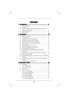
HDDs .... 26 2.12 Driver Installation Guide 26 2.13 Installing Windows® 2000 / XP / XP 64-bit / VistaTM Without RAID Functions 27 2.14 Installing Windows® 2000 / XP / XP 64-bit / VistaTM With RAID Functions 27 2.15 Untied Overclocking Technology 28 3 . BIOS SETUP UTILITY 29 3.1 Introduction - ASRock ALiveNF4G-DVI | User Manual - Page 4
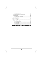
3.5.1 Boot Settings Configuration 42 3.6 Security Screen 43 3.7 Exit Screen 44 4 . Software Support 45 4.1 Install Operating System 45 4.2 Support CD Information 45 4.2.1 Running Support CD 45 4.2.2 Drivers Menu 45 4.2.3 Utilities Menu 45 4.2.4 Contact Information 45 APPENDIX: AMD's Cool - ASRock ALiveNF4G-DVI | User Manual - Page 5
of this manual occur, the updated version will be available on ASRock website without further notice. You may find the latest VGA cards and CPU support lists on ASRock website as well. ASRock website http://www.asrock.com 1.1 Package Contents 1 x ASRock ALiveNF4G-DVI Motherboard (Micro ATX - ASRock ALiveNF4G-DVI | User Manual - Page 6
- CPU Frequency Stepless Control (see CAUTION 4) - ASRock U-COP (see CAUTION 5) - Boot Failure Guard (B.F.G.) - 2 x PCI slots - 1 x PCI Express x16 slot - 1 x PCI Express x1 slot - Integrated NV44 graphics DX9.0 VGA - Pixel Shader 3.0 - Max. shared memory 256MB - Dual VGA output support: DVI-D and - ASRock ALiveNF4G-DVI | User Manual - Page 7
3 x USB 2.0 headers (support 6 USB 2.0 ports) (see CAUTION 8) - 4Mb AMI BIOS - AMI Legal BIOS - Supports "Plug and Play" - ACPI 1.1 Compliance Wake Up Events - Supports jumperfree - SMBIOS 2.3.1 Support - Drivers, Utilities, AntiVirus Software (Trial Version) - CPU Internal Temperature Sensing - CPU - ASRock ALiveNF4G-DVI | User Manual - Page 8
for USB 2.0 works fine under Microsoft® Windows® VistaTM / XP 64-bit / XP SP1 or SP2 / 2000 SP4. 9. Microsoft® Windows® VistaTM driver is not ready yet. We will update it to our website in the future. Please visit our website for Microsoft® Windows® VistaTM driver and related information. ASRock - ASRock ALiveNF4G-DVI | User Manual - Page 9
For system integrators and users who purchase this motherboard and plan to submit Windows® VistaTM Premium and Basic logo, please follow the below table for minimum hardware requirement. Please adopt the CPU, memory, and VGA that we suggest. CPU Memory Sempron 2800+ 512MB x 2 Dual Channel (Premium - ASRock ALiveNF4G-DVI | User Manual - Page 10
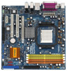
SPK Bottom: CTR BASS USB 2.0 T: USB0 B: USB1 Top: RJ-45 Top: LINE IN Center: FRONT Bottom: MIC IN CD1 LAN PHY HDMI_SPDIF1 1 AUDIO CODEC HD_AUDIO1 1 Super I/O 4Mb BIOS IDE2 nVidia Dual Core CPU FSB1GHz ` GeForce 6100 Chipset CPU_FAN1 PCI EXPRESS ALiveNF4G-DVI PCIE1 SATAII ATA133 RoHS - ASRock ALiveNF4G-DVI | User Manual - Page 11
ASRock DVI I/O 1 2 3 4 7 5 8 6 9 13 12 11 10 1 PS/2 Mouse Port (Green) 2 Parallel Port 3 RJ-45 Port 4 Side Speaker (Gray) 5 Rear Speaker (Black) 6 Central / Bass (Orange) 7 Line In (Light Blue) * 8 Front Speaker (Lime) 9 Microphone (Pink) 10 USB Multi-Streaming function, you need - ASRock ALiveNF4G-DVI | User Manual - Page 12
2. Installation ALiveNF4G-DVI is a Micro ATX form factor (9.6-in x 9.6-in, 24.4 cm x 24.4 cm) motherboard. Before you install the motherboard, study the configuration of your chassis to ensure that the motherboard fits into it. Pre-installation Precautions Take note of the following precautions - ASRock ALiveNF4G-DVI | User Manual - Page 13
Golden Triangle STEP 1: Lift Up The Socket Lever Socket Corner STEP 2 / STEP 3: STEP 4: Match The CPU Golden Triangle Push Down And Lock To The Socket Corner The Socket Lever 2.2 Installation of CPU Fan and Heatsink After you install the CPU into this motherboard, it is necessary to install - ASRock ALiveNF4G-DVI | User Manual - Page 14
2.3 Installation of Memory Modules (DIMM) ALiveNF4G-DVI motherboard provides four 240-pin DDRII (Double Data Rate II) DIMM slots, and supports Dual Channel Memory Technology. For dual channel configuration, you always need to install identical (the same brand, speed, size and chip-type) DDRII DIMM - ASRock ALiveNF4G-DVI | User Manual - Page 15
matches the break on the slot. notch break notch break The DIMM only fits in one correct orientation. It will cause permanent damage to the motherboard and the DIMM if you force the DIMM into the slot at incorrect orientation. Step 3. Firmly insert the DIMM into the slot until the retaining - ASRock ALiveNF4G-DVI | User Manual - Page 16
and 2 PCI slots on ALiveNF4G-DVI motherboard. PCIE Slots: PCIE1 (PCIE x16 slot) is used for PCI Express cards with x16 lane width graphics cards. PCIE2 (PCIE x1 slot) is used for PCI Express cards with x1 lane width graphics cards, such as Gigabit LAN card, SATA2 card, etc. PCI Slots: PCI slots are - ASRock ALiveNF4G-DVI | User Manual - Page 17
capability of the system memory. If you do not adjust the BIOS setup, the default value of "Share Memory", [Auto], will disable VGA/D-Sub function when the add-on VGA card is inserted to this motherboard. 4. Install the onboard VGA driver and the add-on PCI Express VGA card driver to your system. If - ASRock ALiveNF4G-DVI | User Manual - Page 18
enable (see p.10, No. 2) +5V +5VSB +5VSB (standby) for PS/2 or USB wake up events. Note: To select +5VSB, it requires 2 Amp and higher standby not clear the CMOS right after you update the BIOS. If you need to clear the CMOS when you just finish updating the BIOS, you must boot up the system - ASRock ALiveNF4G-DVI | User Manual - Page 19
only one IDE device on this motherboard, please set the IDE device as "Master". Please refer to the instruction of your IDE device vendor for p.10, No. 10) SATAII_1 SATAII_2 These Serial ATAII (SATAII) connectors support SATAII or SATA hard disk for internal storage devices. The current SATAII - ASRock ALiveNF4G-DVI | User Manual - Page 20
to the power connector of the power supply. Besides two default USB 2.0 ports on the I/O panel, there are three USB 2.0 headers on this motherboard. Each USB 2.0 header can support two USB 2.0 ports. This header supports an optional wireless transmitting and receiving infrared module. This connector - ASRock ALiveNF4G-DVI | User Manual - Page 21
to the ground pin. Though this motherboard provides 4-Pin CPU fan (Quiet Fan) support, the 3-Pin CPU fan still can work successfully even without the fan speed control function. If you plan to connect the 3-Pin CPU fan to the CPU fan connector on this motherboard, please connect it to Pin 1-3. Pin - ASRock ALiveNF4G-DVI | User Manual - Page 22
cable to this header if the Game port bracket is installed. RRXD1 DDTR#1 DDSR#1 CCTS#1 1 RRI#1 RRTS#1 GND TTXD1 DDCD#1 This COM1 header supports a serial port module. 1 GND SPDIFOUT +5V HDMI_SPDIF header, providing SPDIF audio output to HDMI VGA card, allows the system to connect HDMI Digital - ASRock ALiveNF4G-DVI | User Manual - Page 23
the black end (A) of HDMI_SPDIF cable to the HDMI_SPDIF header on the motherboard. Then connect the white end (B or C) of HDMI_SPDIF cable to end (3-pin) SPDIFOUT GND blue black USB+COM Port Bracket (Optional) This USB+COM port bracket can support 2 additional USB 2.0 ports and 1 COM port. Please - ASRock ALiveNF4G-DVI | User Manual - Page 24
the system to connect HDMI Digital TV/projector/ LCD devices. To use HDMI function on this motherboard, please carefully follow the below steps. •Step 1. Install the HDMI VGA card to the PCI Express Graphics slot on this motherboard. For the proper installation of HDMI VGA card, please refer to the - ASRock ALiveNF4G-DVI | User Manual - Page 25
guide. Some default setting of SATAII hard disks may not be at SATAII mode, which operate with the best performance. In order to enable SATAII function, please follow the below instruction website for details: http://www.hitachigst.com/hdd/support/download.htm The above examples are just for your - ASRock ALiveNF4G-DVI | User Manual - Page 26
adopts nVidia® nForce 410 MCP southbridge chipset that supports Serial ATA (SATA) / Serial ATAII (SATAII) hard disks and RAID functions. You may install SATA / SATAII hard disks on this motherboard for internal storage devices. This section will guide you to install the SATA / SATAII hard disks - ASRock ALiveNF4G-DVI | User Manual - Page 27
to install Windows® 2000, Windows® XP or Windows® XP 64-bit on your SATA / SATAII HDDs without RAID functions, you don't have to make a SATA / SATAII driver diskette. Besides, there is no need for you to change the BIOS setting. You can start to install Windows® 2000, Windows® XP or Windows® XP 64 - ASRock ALiveNF4G-DVI | User Manual - Page 28
for Windows Guide 2.15 Untied Overclocking Technology This motherboard supports Untied Overclocking Technology, which means during overclocking, FSB enjoys better margin due to fixed PCI / PCIE buses. Before you enable Untied Overclocking function, please enter "Overclock Mode" option of BIOS setup - ASRock ALiveNF4G-DVI | User Manual - Page 29
the BIOS SETUP UTILITY to configure your system. The Flash Memory on the motherboard stores the BIOS SETUP UTILITY. You may run the BIOS SETUP off and then back on. Because the BIOS software is constantly being updated, the following BIOS setup screens and descriptions are for reference purpose - ASRock ALiveNF4G-DVI | User Manual - Page 30
Function Description Moves cursor left or right to select BIOS Version : ALiveNF4G-DVI BIOS P1.0 Processor Type : AMD Athlon(tm) 64 Processor 3400+ (64bit supported) Processor Speed : 2200 MHz Microcode Update : F7A/3A L1 Cache Size : 128KB L2 Cache Size : 512KB Total Memory - ASRock ALiveNF4G-DVI | User Manual - Page 31
CPU Configuration Overclock Mode CPU Frequency (MHz) PCIE Frequency (MHz) Boot Failure Guard CPU Spread Spectrum PCIE Spread Spectrum SATA Spread Spectrum HT Spread Spectrum Cool' n' Quiet Dual Core Support Processor Maximum Multiplier Processor Maximum Voltage Multiplier/Voltage Change Memory - ASRock ALiveNF4G-DVI | User Manual - Page 32
. However, it is recommended to keep the default value for system stability. BIOS SETUP UTILITY Advanced CPU Configuration Overclock Mode CPU Frequency (MHz) PCIE Frequency (MHz) Boot Failure Guard CPU Spread Spectrum PCIE Spread Spectrum SATA Spread Spectrum HT Spread Spectrum Cool' n' Quiet - ASRock ALiveNF4G-DVI | User Manual - Page 33
Voltage This item will show when "Multiplier/Voltage Change" is set to [Manual]; otherwise, it will be hidden. You may set the value from [1.550V] value of this item. Memory Clock This item can be set by the code using [Auto]. You can set one of the standard values as listed: [200 MHz (DDRII - ASRock ALiveNF4G-DVI | User Manual - Page 34
]. The default value is [Auto]. 3.3.2 Chipset Configuration BIOS SETUP UTILITY Advanced Chipset Settings Onboard LAN Onboard HD Audio Front Panel Controller Share Memory Primary Graphics Adapter [Enabled] [Auto] [Auto] [Auto] [PCI] CPU-NB Link Speed CPU-NB Kink Width NB-SB Link Speed [Auto - ASRock ALiveNF4G-DVI | User Manual - Page 35
to [Disabled], the function "Repost Video on STR Resume" will be hidden. Repost Video on STR Resume This feature allows you to repost video on STR resume. (STR refers to suspend to RAM.) Away Mode Support Use this item to enable or disable Away Mode support under Windows® XP Media Center OS. The - ASRock ALiveNF4G-DVI | User Manual - Page 36
plan to use this motherboard to submit Windows® VistaTM certification. 3.3.4 IDE Configuration Advanced BIOS SETUP UTILITY IDE SATAII HDDs can not be accessed until you finish configuring RAID functions in nVidia BIOS / Windows RAID Utility. HDD Fast Detection Configuratin optins: [Enabled] and - ASRock ALiveNF4G-DVI | User Manual - Page 37
BIOS SETUP UTILITY Advanced Primary IDE Master Device Vendor Size LBA Mode Block Mode PIO Mode Async DMA Ultra DMA S.M.A.R.T. :Hard Disk :MAXTOR 6L080J4 :80.0 GB :Supported :16Sectors :4 :MultiWord DMA-2 :Ultra DMA-6 :Supported disk > 512 MB under DOS and Windows; for Netware and UNIX user, select - ASRock ALiveNF4G-DVI | User Manual - Page 38
]. 32Bit Data Transfer Use this item to enable 32-bit access to maximize the IDE hard disk data transfer rate. 3.3.5 PCIPnP Configuration BIOS SETUP UTILITY Advanced Advanced PCI / PnP Settings WARNING: Setting wrong values in below sections may cause system to malfunction. Value in units of - ASRock ALiveNF4G-DVI | User Manual - Page 39
Channel Parallel Port IRQ OnBoard Game Port OnBoard MIDI Port [Enabled] [3F8 / IRQ4] [Disabled] [378] [ECP + EPP] [1.9] [DMA3] [IRQ7] [Enabled] [Disabled] Allow BIOS to Enable or Disable Floppy Controller. +F1 F9 F10 ESC Select Screen Select Item Change Option General Help Load Defaults Save and - ASRock ALiveNF4G-DVI | User Manual - Page 40
it. Configuration options: [Disabled], [300], and [330]. 3.3.8 USB Configuration BIOS SETUP UTILITY Advanced USB Configuration USB Controller USB 2.0 Support Legacy USB Support [Enabled] [Enabled] [Disabled] To enable or disable the onboard USB controllers. +F1 F9 F10 ESC Select Screen Select - ASRock ALiveNF4G-DVI | User Manual - Page 41
the legacy USB support. 3.4 Hardware Health Event Monitoring Screen In this section, it allows you to monitor the status of the hardware on your system, including the parameters of the CPU temperature, motherboard temperature, CPU fan speed, chassis fan speed, and the critical voltage. BIOS SETUP - ASRock ALiveNF4G-DVI | User Manual - Page 42
ESC Exit v02.54 (C) Copyright 1985-2003, American Megatrends, Inc. 3.5.1 Boot Settings Configuration BIOS SETUP UTILITY Boot Boot Settings Configuration Boot From Network Bootup Num-Lock [Disabled] [On] To set to [On], it will automatically activate the Numeric Lock function after boot-up. 42 - ASRock ALiveNF4G-DVI | User Manual - Page 43
you may set or change the supervisor/user password for the system. For the user password, you may also clear it. BIOS SETUP UTILITY Main Advanced H/W Monitor Boot Security Exit Security Settings Supervisor Password : Not Installed User Password : Not Installed Change Supervisor Password - ASRock ALiveNF4G-DVI | User Manual - Page 44
and Exit When you select this option, it will pop-out the following message, "Discard changes and exit setup?" Select [OK] to exit the BIOS SETUP UTILITY without saving any changes. Discard Changes When you select this option, it will pop-out the following message, "Discard changes?" Select [OK] to - ASRock ALiveNF4G-DVI | User Manual - Page 45
available devices drivers including ASRock Express GbL PCI Express LAN card driver if the system detects the installed devices. Please install the necessary drivers to activate the devices. 4.2.3 Utilities Menu The Utilities Menu shows the applications software that the motherboard supports. Click - ASRock ALiveNF4G-DVI | User Manual - Page 46
feature, please make sure to install "AMD Processor Driver" from the "Support CD" first. If you are using Windows® 2000/XP operating system, please follow the instruction below to enable AMD's Cool 'n' QuietTM technology: 1. From the Windows® 2000/XP operating system, click the Start button. Select
-
 1
1 -
 2
2 -
 3
3 -
 4
4 -
 5
5 -
 6
6 -
 7
7 -
8
-
9
-
10
-
11
-
12
-
13
-
14
-
15
-
16
-
17
-
18
-
19
-
20
-
21
-
22
-
23
-
24
-
25
-
26
-
27
-
28
-
29
-
30
-
31
-
32
-
33
-
34
-
35
-
36
-
37
-
38
-
39
-
40
-
41
-
42
-
43
-
44
-
45
-
46
 |
 |
1
ALiveNF4G-DVI
User Manual
Version 1.1
Published August 2006
Copyright©2006 ASRock INC. All rights reserved.